- Table of Contents
-
- H3C S9500 Operation Manual-Release1648[v1.24]-08 System Volume
- 00-1Cover
- 01-Command Line Interface Configuration
- 02-Login and User Interface Configuration
- 03-FTP and TFTP Configuration
- 04-HA Configuration
- 05-NQA Configuration
- 06-NetStream Configuration
- 07-NTP Configuration
- 08-RMON Configuration
- 09-SNMP Configuration
- 10-Packet Statistics Accounting Configuration
- 11-Device Management Configuration
- 12-Configuration File Management Configuration
- 13-File System Management Configuration
- 14-Cluster Management Configuration
- 15-System Maintenance and Debugging Configuration
- 16-Information Center Configuration
- 17-PoE Configuration
- 18-Clock Module Configuration
- 19-ACSEI Server Configuration
- 20-OAP Module Configuration
- Related Documents
-
| Title | Size | Download |
|---|---|---|
| 14-Cluster Management Configuration | 186.1 KB |
Chapter 1 HGMP V1 Configuration
1.2.1 Enabling HGMP Server on a Management Device
1.2.2 Upgrading Software on a Switch through the Management Device
1.2.3 Saving Configuration Information about Connected Switches
1.2.4 Setting the State and Alias of a Switch
1.2.5 Configuring a Specific Low-End Switch through the Management Device
1.3 Displaying and Debugging HGMP Server
1.4 HGMP V1 Configuration Example
2.2 NDP Configuration Task List
2.2.1 Enabling NDP in the System
2.2.2 Configuring NDP on a Port
2.2.3 Configuring the Aging Timer for NDP Information
2.2.4 Configuring the Interval to Send NDP Packets
2.3 Displaying and Maintaining NDP
Chapter 1 HGMP V1 Configuration
When configuring HGMPv1, go to these sections for information you are interested in:
l Displaying and Debugging HGMP Server
l HGMP V1 Configuration Example
1.1 HGMP V1 Overview
HGMP has two versions: HGMP V1 and HGMP V2.
l HGMP V1 is mainly applied in network environments where networking and services are simple to provide a convenient management mode.
l HGMP V2 is mainly applied in complicated network environments to provide more diversified, flexible, and personalized services. It features convenient networking, flexible management, abundant functions, and high reliability.
l Cluster members managed by HGMP V2 must support the layer 3 protocol stack. Those cluster members that do not support the layer 3 protocol stack can be managed by HGMP V1 only.
l HGMP V1 is implemented by HGMP Server and HGMP Client. An HGMP Server resides on a management device. It provides a command interface for users and is in charge of displaying maintenance commands. It also provides specific data structures to store the information about the switches attached to it. HGMP Client responds to the maintenance and query commands issued by the management device and operates accordingly. It also maintains the communication with the management device.
HGMP V1 can be implemented as follows:
l Use a H3C S9500 series routing switch as the HGMP Server, with switches attached to it as the HGMP Clients.
l Use S2403F or S2008B/S2016B/S2026B/S3026 switches as the HGMP Clients, other switches as the HGMP Servers. Figure 1-1 shows the diagram of a typical network that employs HGMP V1 in this way.
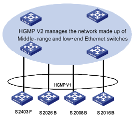
Figure 1-1 Diagram of a network that employs HGMP V1
& Note:
l An S3026/S2008/S2016/S2026/S2403F switch can either be an HGMP Client and be under administration of a H3C S9500 series routing switch or be an HGMP Server and administrate switches. But it cannot be both an HGMP Client and an HGMP Server simultaneously in a network.
l Currently, S9500 Series Switches support HGMP V1 as well as NDP in HGMP V2.
1.2 HGMP Server Configuration
This section covers these topics:
l Enabling HGMP Server on a Management Device
l Upgrading Software on a Switch through the Management Device
l Saving Configuration Information about Connected Switches
l Setting the State and Alias of a Switch
l Configuring a Specific Low-End Switch through the Management Device
1.2.1 Enabling HGMP Server on a Management Device
& Note:
The management device here refers to a switch, which administrates the switches connected to it using HGMP V1.
Perform the following configuration to enable HGMP Server on a management device:
|
To do… |
Use the command… |
Remarks |
|
Enable HGMP Server globally and enter HGMP view. |
hgmpserver enable |
Available in system view |
|
Disable HGMP Server globally |
hgmpserver disable |
Available in system view |
|
Restore the default global HGMP Server configuration |
undo hgmpserver |
Available in system view |
|
Enable HGMP on the port |
hgmpport enable |
Available in Ethernet port view |
|
Disable HGMP on the port |
hgmpport disable |
Available in Ethernet port view |
|
Configure the switches connected to the port to be organized in star topology. |
spanning-hub { enable | disable } slotno subslot port-list |
Available in HGMP view |
|
Display the information about the star-type network mode of the port. |
query hgmpport-mode |
Available in HGMP view |
To implement HGMP, you must enable HGMP globally first, and then enable HGMP on the port.
To manage cascaded switches, use the spanning-hub { enable | disable } slotno subslot port-list command on the corresponding ports of the management device.
An HGMP Server maintains each switch by its lanswitch-loc number. A lanswitch-loc number comprises slot number, subslot number, port number and sequence number (for example 3/1/3-/). However, this number cannot indicate the actual physical position of a switch in a star network topology. A lanswitch-loc number is in the form of slot/subslot/port-/p1/p2/, among which:
port is a port number on the management device that the switch is connected to.
p1 is a port number on the layer 1 switch that the switch is connected to.
p2 is a port number on the layer 2 switch that the switch is connected to.
For example, lanswitch-loc of 3/1/3-/ identifies a layer 1 switch directly connected to the port 3 on subslot 1 of slot 3 of the management device.
Whereas 3/1/3-/2/ identifies a layer 2 switch connected to port 2 of layer 1 switch. Its root node is the 3/1/3 port of the management device.
A value of 3/1/3-/2/1/ identifies a Layer 3 switch connected to port 1 of a Layer 2 switch. Its root node is the 3/1/3 port of the management device.
1.2.2 Upgrading Software on a Switch through the Management Device
With HGMP employed, you can use the HGMP Server to upgrade the software run on the switches connected to the HGMP Server.
I. Downloading the upgrade program to the flash memory of the management device
Note that: Do not try to download the upgrade program using Boot ROM menu items when the management device starts, instead, you need to download the upgrade program to the flash memory of the management device using FTP or TFTP services after the management device starts.
Following is an example to download upgrade program using TFTP with the assumption that:
l The serial port of the computer that is used to configure the management device locally is connected to the Console port of the management device.
l The network adapter of the computer is connected to an Ethernet port of the management device.
l Run TFTP Server on the computer to enable the management device, which operates as a TFTP Client, to download the upgrade program.
l The computer and the management device are in the same network segment.
Perform the following configuration to download a file using TFTP on the management device:
|
To do… |
Use the command… |
Remarks |
|
Download files using TFTP |
tftp tftp-server get source-file [ dest-file ] |
Available in user view |
Substitute the tftp-server argument with the IP address or host name of the TFTP server, the source-file argument with the name of the file to be downloaded, and the dest-file argument with the file name to save the downloaded file as. For more information about the tftp get command, refer to the corresponding description in the command manual..
II. Downloading the upgrade program from the flash memory of the management device to the upgrade memory section
Perform the following configuration to load the upgrade program to the upgrade memory section of the management device:
|
To do… |
Use the command… |
Remarks |
|
Load the upgrade program for the switch to upgrade memory section of the management device |
load lswprogram filename |
Available in HGMP view |
Substitute the filename argument with the file name of the upgrade program in the Flash memory.
III. Upgrading a specified switch
When upgrading the software running on a switch, you need to provide position information about the switch. You can use the display lanswitch all command to acquire the position parameters of a registered switch.
Perform the following configuration to upgrade a specified switch:
|
To do… |
Use the command… |
Remarks |
|
Upgrade a specified switch |
upgrade lanswitch lanswitch-loc { app | bootrom } |
Available in HGMP view |
|
Display the information about a registered switch |
display lanswitch { all | port slot subslot port | position lanswitch-loc } [ error ] [ inactive ] |
Available in any view |
Substitute the lanswitch-loc argument with the position information of the desired switch in the form of those described in section Enabling HGMP Server on a Management Device, such as 3/1/1-/.
IV. Rebooting the connected switch to make the upgrade take effect
|
To do… |
Use the command… |
Remarks |
|
Reset a specified switch |
reset lanswitch lanswitch-loc |
Available in HGMP view |
Make sure the specified switch have enough free flash memory to hold the upgrade program.
V. Deleting a upgrade program from the management device
As a management device has limited flash memory, you need to delete an upgrade program after finishing upgrading a switch using it to make room for other upgrade programs.
Perform the following configuration to delete an upgrade program from the management device:
|
To do… |
Use the command… |
Remarks |
|
Delete a upgrade program from the management device |
delete [ /unreserved ] file-url |
Available in user view |
For more information about the delete command, refer to File System Management Commands.
1.2.3 Saving Configuration Information about Connected Switches
Perform the following configuration to save configuration information about the managed switches into the management device:
|
To do… |
Use the command… |
Remarks |
|
Save the configuration information of a specified switch to the memory of the management device. |
save lswconfig lanswitch-loc |
Available in HGMP view |
|
Save the configuration information of a specified switch to the flash memory. |
backup lswconfig |
Available in HGMP view |
Configuration information about a specified switch that is saved to the memory of the management device using the save lswconfig command gets lost after you reboot the management device.
The backup lswconfig command saves the configuration information collected by the save lswconfig command to the flash memory. As data saved in the flash memory does not get lost even if the management device is rebooted. Therefore, with its configuration information saved in the flash memory, you can quickly restore the operating state of a switch using its configuration information in the case of switch resetting.
# Save the configuration information about the Ethernet switch directly connected to the 1/1/20-/ port to the memory.
[H3C-hgmp] save lswconfig 1/1/20-/
Waiting........
# Write the configuration information saved in the memory to the flash memory.
[H3C-hgmp] backup lsw
Writing lanswitch configuration to flash......
1.2.4 Setting the State and Alias of a Switch
Contrary to the fact that HGMP identifies switches using their position parameters, it is impossible for users to locate a managed switch by its position parameter. An intuitive alternative is, to set aliases for switches using the set lswname command.
In addition, you can set the state of a managed switch to be active or inactive on the management device.
Perform the following configuration to set the state and alias of a managed switch:
|
To do… |
Use the command… |
Remarks |
|
Set the state of a specified switch |
set lanswitch lanswitch-loc { inactive | active } |
Available in HGMP view |
|
Configure an alias for an switch |
set lswname lanswitch-loclist name-list |
Available in HGMP view |
|
Remove a configured alias |
undo set lswname lanswitch-loclist |
Available in HGMP view |
Save the configuration information to the flash memory of the management device using the backup lswconfig command.
1.2.5 Configuring a Specific Low-End Switch through the Management Device
S2008B/S2016B/S2026B and S2403F switches are all low-end switches. After enabling HGMP Server on the management device and HGMP Client on these low-end switches, you can manage the connected low-end switches through the management device.
Using HGMP, you can configure any connected low-end switch by configuring the management device. You can perform the following configuration on the management device to configure the connected low-end switches: port rate configuration, port aggregation configuration, VLAN configuration, address table configuration, VLAN management configuration, and so on.
I. Specifying default configuration settings
These operations are applicable to S2008B/S2016B/S2026B/S3026 switches.
You can specify the configuration of a switch, such as port rate, flow control, duplex settings and tag status of the port, to be the default configuration settings and apply it to all switches that are of the same model, through which you can have other switches automatically configured using the auto config command.
Perform the following configuration to specify default configuration settings:
|
To do… |
Use the command… |
Remarks |
|
Specify the configuration of a switch to be the default configuration settings |
set lswconfig lanswitch-loc asdefault |
Available in HGMP view |
To configure a switch, you need to enter the configuration view of the switch on the management device first.
Perform the following configuration on the management device to enter the configuration view of a specified switch:
|
To do… |
Use the command… |
Remarks |
|
Enter the configuration view of a specified switch |
lanswitch lanswitch-loc |
Available in HGMP view |
You can configure port rate, port aggregation, VLAN, and so on for a specified switch on the management device only after you enter the configuration view of the specified Ethernet switch on the management device.
II. Performing port, VLAN and other configurations for a specified switch
These operations are applicable to S2008B/S2016B/S2026B/S3026 switches.
Perform the following configuration for a specified switch on the management device:
|
To do… |
Use the command… |
Remarks |
|
Aggregate multiple ports to one port |
set link-aggregation port-list { sa | dasa } groupid |
Available in lanswitch view |
|
Disable the address learning function of the port of the switch |
lock port port-list |
Available in lanswitch view |
|
Query address aged time of the switch |
query address agedtime |
Available in lanswitch view |
|
Query gateway IP address of the switch |
query gatewayip |
Available in lanswitch view |
|
Query manage IP address of the switch |
query manageip vlan-id |
Available in lanswitch view |
|
Query lock state of the port of the switch |
query port lockstate |
Available in lanswitch view |
|
Query system information of the switch |
query system info |
Available in lanswitch view |
|
Query VDSL link rates of the port |
query vdsllink [ port-list ] |
Available in lanswitch view |
|
Query VLAN state information of the switch |
query vlanstate |
Available in lanswitch view |
|
Set address aged time of the switch |
set address agedtime agedtimevalue |
Available in lanswitch view |
|
Set the gateway IP address of the switch |
set gatewayip ip-address |
Available in lanswitch view |
|
Cancel the setting of gateway IP address of the switch |
undo set gatewayip ip-address |
Available in lanswitch view |
|
Set the management IP address of the switch |
set manageip ip-address netmask [ vlan-id ] |
Available in lanswitch view |
|
Cancel the setting of the management IP address of the switch |
undo set manageip ip-address netmask [ vlan-id ] |
Available in lanswitch view |
|
Set the VDSL link rates of the port of the switch |
set vdsllink port-list uprate uprate-list downrate downrate-list |
Available in lanswitch view |
|
Query how ports are aggregated |
query link-aggregation |
Available in lanswitch view |
|
Configure the port tag status, and the relationship between switch ports and VLANs. |
set port port-list vlanid vlan-id-list [ tagged | untagged ] |
Available in lanswitch view |
|
Set flow control configuration for ports |
flow port port-list { both | none } |
Available in lanswitch view |
|
Set duplex state for ports |
duplex port port-list { auto | half | full } |
Available in lanswitch view |
|
Set port rate for ports |
speed port port-list { auto | 10m | 100m } |
Available in lanswitch view |
|
Close specified switch ports |
close port port-list |
Available in lanswitch view |
|
Enable specified switch ports |
undo close port port-list |
Available in lanswitch view |
|
Query port states of specified ports |
query port port-list |
Available in lanswitch view |
|
Set port mirroring |
set mirror monitor-port monitor-port [ port-list ] |
Available in lanswitch view |
|
Cancel port mirroring configuration |
undo set mirror |
Available in lanswitch view |
|
Query information about port mirroring |
query mirror |
Available in lanswitch view |
|
Set loopback test for specified ports |
set loop-test { internal | external } port-list |
Available in lanswitch view |
|
Configure the switch to use the default configuration |
auto config default port-start-vlanid |
Available in lanswitch view |
|
Set the priority for specified ports |
set priority { high | low } port-list |
Available in lanswitch view |
|
Set the QoS weight for the ports with high priority |
set qos-weight weight |
Available in lanswitch view |
|
Cancel the QoS weight configured for the ports with high priority |
undo set qos-weight |
Available in lanswitch view |
|
Set attributes for specified VLAN |
set vlanid vlanid port-list |
Available in lanswitch view |
|
Restore the default VLAN attributes |
undo set vlanid vlanlist |
Available in lanswitch view |
|
Query the rmon statistics of the switch |
query rmon port port-list { forward | trans |recv | err | all } |
Available in lanswitch view |
|
Set a password |
set superview-password password |
Available in lanswitch view |
|
Cancel the password |
undo set superview-password |
Available in lanswitch view |
|
Set a domain name for the switch |
set sysname name-word |
Available in lanswitch view |
|
Save or remove the configuration file |
set config-flash { write | erase } |
Available in lanswitch view |
|
Query the current configuration of switch |
query active-configuration |
Available in lanswitch view |
|
Query the configuration information saved on the switch |
query saved-configuration |
Available in lanswitch view |
You can use the auto config command to configure specified ports with the default configuration settings, such as port rate, flow control, duplex state, and tag state. When executing the auto config command, you must provide the port-start-vlanid argument to specify the starting VLAN ID of the specified port, through which you can add multiple ports to one VLAN.
You can perform these configurations locally. Refer to the corresponding operation manual of the switch you are configuring for more information.
III. Configuring the address table for a specified switch
The configuration is applicable to S2008B/S2016B/S2026B/S3026 switches.
Perform the following configuration to configure the address table for the S2008B/S2016B/S2026B/S3026 switch on the management device:
|
To do… |
Use the command… |
Remarks |
|
Add an address entry |
add addritem mac-addr { unicast port [ aged | noaged | permanent ] | multicast vlanid port-list mctype } |
Available in lanswitch view |
|
Remove a multicast address entry |
delete multicast mac-addr vlanid vlanid |
Available in lanswitch view |
|
Remove an unicast address entry |
delete uniaddr mac-addr |
Available in lanswitch view |
|
Modify a multicast address entry |
modify multiaddr mac-addr vlanid port-list mctype |
Available in lanswitch view |
|
Modify an unicast address entry |
modify uniaddr mac-addr { aged | noaged | permanent } |
Available in lanswitch view |
|
Search specified multicast addresses in the address table |
search multiaddr mac-addr-list vlanid vlanid-list |
Available in lanswitch view |
|
Search specified unicast addresses in the address table |
search uniaddr mac-addr-list |
Available in lanswitch view |
|
Display the unicast address entries of a specified port |
query uniaddr port spec-port index shownum |
Available in lanswitch view |
|
Display the multicast address entries in a specified VLAN |
query multiaddr vlanid vlanid |
Available in lanswitch view |
|
Query the number of the occupied address entries |
query used addrnum |
Available in lanswitch view |
|
Query the current configuration of the connected switches |
query active-configuration |
Available in lanswitch view |
|
Query the startup configuration of the connected switches |
query saved-configuration |
Available in lanswitch view |
You can also perform these configurations locally. Refer to the operation manual of the switch you are configuring for more information.
IV. Configuring an S2403F switch
Perform the following configuration on the management device to configure an S2403F switch:
|
To do… |
Use the command… |
Remarks |
|
Configure the switch using the default configuration settings |
auto config default port-start-vlanid |
Available in lanswitch view |
|
Display the management IP address and subnet mask of the switch and the IP address of the default gateway |
query ip address |
Available in lanswitch view |
|
Set or remove the management IP address and subnet mask of the switch and the IP address of the default gateway |
set ip address ip-address mask [ gateway-address ] |
Available in lanswitch view |
|
Set the management MAC address for the switch |
set mac mac-address |
Available in lanswitch view |
|
Configure the port tag status, and the relationship between switch ports and VLANs |
set port port-list vlanid vlan-id-list [ tagged | untagged ] |
Available in lanswitch view |
|
Set the VLAN data of the Ethernet switch |
set vlan vlan-index-list { vlanid vlan-id-list [ port-list ] | broadcast port-list [ vlan-id-list ] } |
Available in lanswitch view |
|
Set working mode for specified ports of the Ethernet switch |
set workmode port-list { auto | 10m-full | 10m-half | 100m-full | 100m-half } |
Available in lanswitch view |
|
Allow the specified port self loopback |
loop port port-list |
Available in lanswitch view |
|
Prohibit the specified port self loopback |
undo loop port port-list |
Available in lanswitch view |
|
Close specified switch ports |
close port port-list |
Available in lanswitch view |
|
Enable specified switch ports |
undo close port port-list |
Available in lanswitch view |
You can use the auto config command to configure specified ports with the default configuration settings, such as port rate, flow control, duplex state, and tag state. When executing the auto config command, you must provide the port-start-vlanid argument to specify the starting VLAN ID of the specified port, through which you can add multiple ports to one VLAN.
You can perform these configurations locally. Refer to the corresponding operation manual of the switch you are configuring for more information.
1.3 Displaying and Debugging HGMP Server
|
To do… |
Use the command… |
Remarks |
|
Display information about the HGMP server |
display hgmpserver |
Available in any view |
|
Display current operating information about HGMP |
display current-configuration |
Available in any view |
|
Enable/Disable debugging for HGMP Server |
[ undo ] debugging hgmps { all | error | info | packet } |
Available in user view |
1.4 HGMP V1 Configuration Example
I. Network requirements
Switch A serves as the management device. Switch B and Switch C are connected to the Ethernet 1/1/1 port and Ethernet 1/1/2 port of Switch A.
II. Network diagram
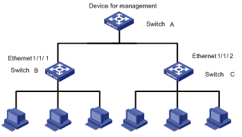
Figure 1-2 Network diagram for HGMP group management
III. Configuration procedure
# Enable HGMP Client on Switch B (refer to the command manual and operation manual of Switch B for detailed instructions).
The following is only an example. The actual configuration varies with switch model and the network circumstances.
# Enable HGMP Server on Switch A.
[H3C] hgmpserver enable
Start HGMP protocol successfully!
[H3C-hgmp] spanning-hub enable 1 1 1-2
[H3C-hgmp] quit
[H3C] interface ethernet 1/1/1
[H3C-Ethernet1/1/1] hgmpport enable
[H3C-Ethernet1/1/1] interface ethernet 1/1/2
[H3C-Ethernet1/1/2] hgmpport enable
# Use the display command to display the information about the switches registered with Switch A, through which you can obtain position parameters of each switch.
<H3C> display lanswitch all
Lanswitch list.........
------------------
No. 1
------------------
Position : LANSWITCH[1/1/1-/1/]
PortMode : STAR_MODE
Lanswitch Name : lan1
Model : H3C S2008
Device ID : Vc.3.2
MacAddr : 00e0-fc2d-1f9c
Status : NORMAL
------------------
No. 2
------------------
Position : LANSWITCH[1/1/2-/1/]
PortMode : STAR_MODE
Lanswitch Name : lan2
Model : H3C S2026B
Device ID : V10.30.1
MacAddr : 00e0-fc26-dfb7
Status : NORMAL
# Set an alias for the switch 1/1/1-/ on the management device.
[H3C-hgmp] set lswname 1/1/1-/ switch1
# Set duplex state to auto for port 1 of Switch B on the management device.
[H3C-hgmp] lanswitch 1/1/1-/
[H3C-lanswitch1/1/1-/] duplex port 1 auto
# Set duplex state to auto for port 1 of Switch C on the management device.
[H3C-hgmp] lanswitch 1/1/2-/1/
[H3C-lanswitch1/1/2-/1/] duplex port 1 auto
Chapter 2 NDP Configuration
When configuring NDP, go to these sections for information you are interested in:
l Displaying and Maintaining NDP
2.1 Introduction to NDP
As part of HGMP, Neighbor Discovery Protocol (NDP) is used to discover the information about a neighbor device directly connected, including the type, software/hardware version, port connected, ID, port address, and hardware platform of the neighbor device.
A device running NDP periodically sends NDP packets to all ports with NDP enabled while receiving NDP packets from the neighbor device. The device receiving a NDP packet does not forward it, but maintains an NDP neighbor information table on the current device and stores the neighbor information carried in the NDP packets in this table. Besides neighbor device information, NDP packets contain the information about the aging timer for the NDP information, which specifies how long the NDP packets will be stored on the receiving device.
If the NDP neighbor information is not updated even after the aging timer for NDP information expires, the device automatically deletes the entry corresponding to the NDP information from the NDP neighbor information table. If the neighbor information received by the device is different from the original information, the device updates the corresponding entry in the NDP neighbor information table. If the neighbor information received by the device is the same as the original information, the device updates only the aging timer in the NDP neighbor information table.
You can also clear the current NDP information and collect NDP neighbor information again.
& Note:
Upon receipt of NDP packets, a switch with NDP disabled directly forwards the packets to all ports in the same VLAN, while a switch with NDP enabled does not forward any NDP packet.
2.2 NDP Configuration Task List
Complete the following tasks to configure NDP:
|
Task |
Remarks |
|
Required |
|
|
Required |
|
|
Optional |
|
|
Optional |
& Note:
l On the management device, NDP must be enabled in the system and on the ports.
l On member devices and candidate devices, the NDP feature must also be enabled in the system and on the corresponding ports. The aging timer for the NDP information sent from the management device is used during NDP operation.
2.2.1 Enabling NDP in the System
To collect the NDP information sent by the neighbor device, you must enable NDP on the switch. With NDP enabled in the system, the switch periodically collects NDP information, which you can query by using the display ndp command. With NDP disabled in the system, the switch clears all NDP neighbor information stored on it but will still forwards NDP packets.
Follow these steps to enable NDP in the system:
|
To do… |
Use the command… |
Remarks |
|
Enter system view |
system-view |
— |
|
Enable NDP in the system |
ndp enable [ interface port-list | all ] |
By default, NDP is disabled in the system. |
& Note:
When you try to enable NDP on all ports, NDP is enabled only on the common Ethernet ports and GigabitEthernet ports that support NDP interface boards.
2.2.2 Configuring NDP on a Port
You can control the collection of neighbor device information for the specified port by enabling/disabling NDP on the port. With NDP enabled on the port and in the system, the system periodically collects the NDP neighbor information about the adjacent node of the port. With NDP disabled on the port, the system cannot collect NDP information through the port.
Follow these steps to enable NDP on a port:
|
To do… |
Use the command… |
Remarks |
|
Enter system view |
system-view |
— |
|
Enter Ethernet port view |
interface interface-type interface-number |
Currently, only common Ethernet interface boards and Gigabit Ethernet interface boards support NDP. |
|
Enable NDP on the port |
ndp enable |
By default, NDP is disabled on a port. |
2.2.3 Configuring the Aging Timer for NDP Information
Upon receipt of NDP packets, from the aging timer information carried in the packets, the switch can learn about the aging timer for the NDP information of the neighbor device that sent the packets and discards the NDP information of the neighbor device once the aging timer is exceeded. This configuration allows you to set the aging timer for the NDP information of the current device on the neighbor device.
Follow these steps to configure the aging timer for NDP information:
|
To do… |
Use the command… |
Remarks |
|
Enter system view |
system-view |
— |
|
Configure the aging timer for NDP information |
ndp timer aging aging-in-secs |
By default, the aging timer for NDP information is 180 seconds. The aging timer for NDP information must be greater than the interval at which NDP packets are sent; otherwise, the NDP information table will be unstable. |
2.2.4 Configuring the Interval to Send NDP Packets
The NDP information of the adjacent device must be updated periodically to ensure that the switch can update the local NDP neighbor information table in time after the configuration of the adjacent device is changed. You can configure the interval to send NDP packets by using the following command.
Follow these steps to configure the interval to send NDP packets:
|
To do… |
Use the command… |
Remarks |
|
Enter system view |
system-view |
— |
|
Configure the interval at which NDP packets are sent |
ndp timer hello seconds |
By default, NDP packets are sent every 60 seconds. The interval at which NDP packets are sent must be less than the aging timer for NDP information. Otherwise, the NDP information table will be unstable. |
2.3 Displaying and Maintaining NDP
|
To do… |
Use the command… |
Remarks |
|
Display the NDP configuration of the system (including the interval at which packets are sent and the aging timer for NDP information |
display ndp |
Available in any view |
|
Display the NDP neighbor information of the specified port |
display ndp interface port-list |
Available in any view |
|
Clear the statistics of an NDP-enabled port |
reset ndp statistics [ interface port-list ] |
Available in user view |
2.4 NDP Configuration Example
I. Network requirements
l Switch A, Switch B, and Switch C are interconnected.
l Ethernet 1/1/1 on Switch A is connected to Ethernet 1/1/1 on Switch B and Ethernet 1/1/2 on Switch A is connected to Ethernet 1/1/1 on Switch C.
l The information of the neighbor switches Switch B and Switch C that are connected to Switch A should be visible to Switch A through NDP configuration.
II. Network diagram
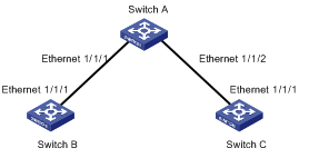
Figure 2-1 Network diagram for NDP configuration
III. Configuration procedure
1) Configure Switch A.
# Enable NDP in the system and on Ethernet 1/1/1 and Ethernet 1/1/2.
<H3C> system-view
System View: return to User View with Ctrl+Z.
[H3C] ndp enable
[H3C] interface ethernet 1/1/1
[H3C-Ethernet1/1/1] ndp enable
[H3C-Ethernet1/1/1] quit
[H3C] interface ethernet 1/1/2
[H3C-Ethernet1/1/2] ndp enable
# Configure the aging timer for NDP information as 200 seconds.
[H3C-Ethernet1/1/2] quit
[H3C] ndp timer aging 200
# Configure NDP packets to be sent every 70 seconds.
[H3C] ndp timer hello 70
2) Configure Switch B (Configure Switch C in a similar way).
# Enable NDP on the device and Ethernet 1/1/1.
<H3C> system-view
System View: return to User View with Ctrl+Z.
[H3C] ndp enable
[H3C] interface ethernet 1/1/1
[H3C-Ethernet1/1/1] ndp enable
& Note:
After the above-mentioned configuration, you can view the information about the neighbor switch connected to the port by issuing the display ndp interface port-list command on Switch A.
