- Table of Contents
-
- H3C S9500 Operation Manual-Release1648[v1.24]-08 System Volume
- 00-1Cover
- 01-Command Line Interface Configuration
- 02-Login and User Interface Configuration
- 03-FTP and TFTP Configuration
- 04-HA Configuration
- 05-NQA Configuration
- 06-NetStream Configuration
- 07-NTP Configuration
- 08-RMON Configuration
- 09-SNMP Configuration
- 10-Packet Statistics Accounting Configuration
- 11-Device Management Configuration
- 12-Configuration File Management Configuration
- 13-File System Management Configuration
- 14-Cluster Management Configuration
- 15-System Maintenance and Debugging Configuration
- 16-Information Center Configuration
- 17-PoE Configuration
- 18-Clock Module Configuration
- 19-ACSEI Server Configuration
- 20-OAP Module Configuration
- Related Documents
-
| Title | Size | Download |
|---|---|---|
| 02-Login and User Interface Configuration | 285.96 KB |
Table of Contents
1.1 Setting Up Configuration Environment Through the Console Port
1.2 Setting Up Configuration Environment Through Telnet
1.2.1 Connecting a PC to the Switch Through Telnet
1.2.2 Accessing a Switch Through Another Switch via Telnet
1.3 Setting Up Configuration Environment Through Modem Dial-up
Chapter 2 User Interface Configuration
2.2 User Interface Configuration
2.2.1 Entering User Interface View
2.2.2 Defining the Login Header
2.2.3 Configuring Asynchronous Port Attributes
2.2.4 Configuring Terminal Attributes
2.2.7 Configuring Modem Attributes
2.3 Displaying and Debugging User Interface
Chapter 3 Management Port Configuration
3.2 Management Port Configuration
Chapter 1 Switch Login
When configuring switch login, go to these sections for information you are interested in:
l Setting Up Configuration Environment Through the Console Port
l Setting Up Configuration Environment Through Telnet
l Setting Up Configuration Environment Through Modem Dial-up
1.1 Setting Up Configuration Environment Through the Console Port
Step 1: As shown in the figure below, to set up the local configuration environment, connect the serial port of a PC (or a terminal) to the console port of the switch with the console cable.
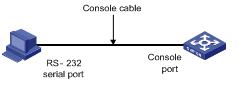
Figure 1-1 Set up the local configuration environment through the console port
Step 2: Run a terminal emulator (such as Terminal of Windows 2000 or HyperTerminal of Windows XP) on the computer. Set the terminal communication parameters as follows: Set “Bits per second” to “9600”, “Data bits” to “8”, “Parity” to “none”, “Stop bits” to “1”, and “Flow control” to “none”, and select the “VT100” as the terminal type..
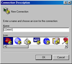
Figure 1-2 Set up new connection
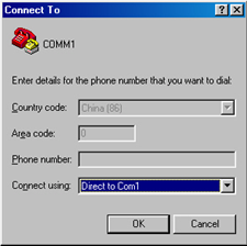
Figure 1-3 Configure the port for connection
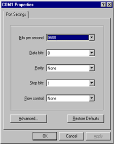
Figure 1-4 Set communication parameters
Step 3: The switch is powered on. Display self-test information of the switch and prompt you to press Enter to show the command line prompt such as <H3C>.
Step 4: Input a command to configure the switch or view the operation state. Input a “?” for help. For details of specific commands, refer to the following chapters.
1.2 Setting Up Configuration Environment Through Telnet
1.2.1 Connecting a PC to the Switch Through Telnet
To telnet to the Ethernet Switch, ensure that the following conditions are satisfied:
l Assign an IP address to the management VLAN interface correctly in the Ethernet Switch (use the ip address command in VLAN interface view).
l Specify the Ethernet port connected with the PC to belong to the management VLAN (use the port command in VLAN view)
l If the PC and the switch’s port connected with the PC reside in the same LAN, their IP addresses must be configured to reside in the same network segment. Otherwise, the PC and the Switch must be reachable to each other.
Then, you can telnet to the Ethernet Switch to configure it.
Follow the given steps below:
Step 1: Before logging into the switch through telnet, you need to configure the Telnet user name and password on the switch through the console port.
& Note:
By default, the password is required for authenticating the Telnet user to log into the switch. If a user tries to log in through Telnet without a password, the system will prompt that the login fails because no password is set.
<H3C> system-view
System View: return to User View with Ctrl+Z.
[H3C] user-interface vty 0
[H3C-ui-vty0] set authentication password simple xxxx (xxxx is the login password of Telnet user)
Step 2: To set up the configuration environment, connect the Ethernet port of the PC to that of the switch via the LAN, as shown in Figure 1-5.
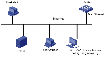
Figure 1-5 Set up configuration environment through telnet
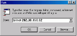
Step 3: Run Telnet on the PC and input the IP address of the VLAN connected to the PC port, as shown in Figure 1-6.
Step 4: The terminal displays “Login authentication!” and prompts the user to input the logon password. After you input the correct password, it displays the command line prompt (such as <H3C>). If the prompt “All user interfaces are used, please try later! The connection was closed by the remote host!” appears, it indicates that the maximum number of Telnet users that can be accessed to the switch is reached at this moment. In this case, please reconnect later. At most 5 Telnet users are allowed to log on to the H3C series switches simultaneously.
Step 5: Use the corresponding commands to configure the switch or to monitor the running state. Enter “?” to get the immediate help. For details of specific commands, refer to the following chapters.
& Note:
l When configuring the switch via Telnet, do not modify the IP address of it unless necessary, for the modification might cut the Telnet connection.
l By default, when a Telnet user passes the password authentication to log on to the switch, he can access the commands at Level 0.
1.2.2 Accessing a Switch Through Another Switch via Telnet
l After a user has logged into a switch, he or she can configure another switch through the switch via Telnet. The local switch serves as Telnet client and the peer switch serves as Telnet server.
l If the ports connecting the two switches are on the same local network, the IP addresses of the two switches must be in the same network segment. Otherwise, a route must be available between the two switches.
As shown in the figure below, after you telnet to a switch, you can run telnet command to log in and configure another switch.
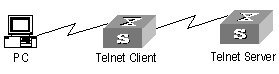
Figure 1-7 Provide Telnet Client service
Step 1: Configure the Telnet user name and password on the Telnet Server through the console port.
& Note:
By default, the password is required for authenticating the Telnet user to log into the switch. If a user logs in via the Telnet without password, he will see the prompt “Login password has not been set !”.
<H3C> system-view
System View: return to User View with Ctrl+Z.
[H3C] user-interface vty 0
[H3C-ui-vty0] set authentication password simple xxxx
Step 2: The user logs in the Telnet Client (switch). For the login process, refer to the section describing “Connecting a PC to the Switch through Telnet”.
Step 3: Perform the following operations on the Telnet Client:
<H3C> telnet xxxx
xxxx is the hostname or IP address of the Telnet Server. If hostname is used, it must be the one configured with the ip host command or the DNS domain name of the Telnet Server.
Step 4: Enter the preset login password and you will see the prompt such <H3C>. If the prompt “All user interfaces are used, please try later! The connection was closed by the remote host!” appears, it indicates that the maximum number of Telnet users that can be accessed to the switch is reached at this moment. In this case, please connect later.
Step 5: Use the corresponding commands to configure the switch or view it running state. Enter “?” to get the immediate help. For details of specific commands, refer to the following chapters.
1.3 Setting Up Configuration Environment Through Modem Dial-up
Step 1: Perform authentication configuration for the modem user via the console port of the switch before the user logs into the switch through a dial-up modem.
& Note:
By default, the modem user is authenticated against password when logging into the switch. If no password is set, the prompt “Login password has not been set !.” will be displayed when the modem user logs in.
<H3C> system-view
System View: return to User View with Ctrl+Z..
[H3C] user-interface aux 0
[H3C-ui-aux0] set authentication password simple xxxx
Step 2: As shown in the figure below, to set up the remote configuration environment, connect the Modems to a PC (or a terminal) serial port and the switch AUX port respectively.
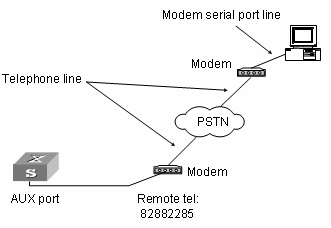
Figure 1-8 Set up remote configuration environment
Step 3: Dial for connection to the switch, using the terminal emulator and Modem on the remote end. The number dialed shall be the telephone number of the Modem connected to the switch. See the two figures below.
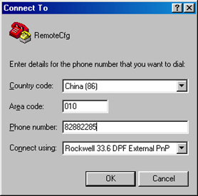
Figure 1-9 Set the dialed number
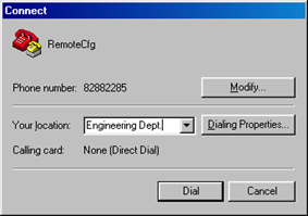
Figure 1-10 Dial on the remote PC
Step 4: Enter the preset login password on the remote terminal emulator and wait for the prompt such as <H3C>. Then you can configure and manage the switch. Enter “?” to get the immediate help. For details of specific commands, refer to the following chapters.
& Note:
By default, when a Modem user logs in, he can access the commands at Level 0.
Chapter 2 User Interface Configuration
When configuring user interface, go to these sections for information you are interested in:
l User Interface Configuration
l Displaying and Debugging User Interface
2.1 User Interface Overview
To facilitate system management, the switches support user interface based configuration for the configuration and management of port attributes. Presently, the S9500 series switches support the following user interface based configuration methods:
l Local configuration via the console port and AUX port
l Local and remote configuration through Telnet on Ethernet port
l Remote configuration through dialing with modem via the AUX port.
According to the above-mentioned configuration methods, there are three types of user interfaces:
l Console user interface
Console user interface is used to log into the switch via the console port. A switch can only have one console user interface.
l AUX user interface
AUX user interface is used to log into the switch locally or remotely with a modem via the AUX port. A switch can only have one AUX user interface. The local configuration for it is similar to that for the console user interface.
l VTY user interface
VTY user interface is used to telnet the switch. A switch can have up to five VTY user interface.
User interface is numbered in the following two ways: absolute number and relative number.
I. Absolute number
The user interfaces of the S9500 routing switch include three types, which are sequenced as follows: console interface (CON), auxiliary interface (AUX) and virtual interface (VTY). A switch has one CON, one AUX and multiple VTYs. The first absolute number is designated as 0; the second one is designated as 1; and so on. This method can specify a unique user interface or a group of interfaces.
It follows the rules below.
l Console user interface is numbered as the first interface designated as user interface 0.
l AUX user interface is numbered as the second interface designated as user interface 1.
l VTY is numbered after AUX user interface. The absolute number of the first VTY is incremented by 1 than the AUX user interface number.
II. Relative number
The relative number is in the format of “user interface type” + “number”. The “number” refers to the internal number for each user interface type. With this numbering method, when performing a configuration operation for user interfaces, you can only specify a same type of user interfaces instead of specifying different types of user interfaces.
It follows the rules below:
l Number of console user interface: console 0.
l Number of AUX user interface: AUX 0.
l Number of VTY: The first VTY interface is designated as VTY 0; the second one is designated as VTY 1, and so on.
2.2 User Interface Configuration
The following sections describe the user interface configuration tasks.
l Entering User Interface View
l Configuring Asynchronous Port Attributes
l Configuring Terminal Attributes
l Configuring Modem Attributes
2.2.1 Entering User Interface View
The following command is used for entering a user interface view. You can enter a single user interface view or multi user interface view to configure one or more user interfaces respectively.
Perform the following configuration in system view.
Follow these steps to enter user interface view:
|
To do… |
Use the command… |
|
Enter a single user interface view or multi user interface views |
user-interface [ type ] first-number [ last-number ] |
2.2.2 Defining the Login Header
The following command is used for configuring the displayed header when user login.
When the users log into the switch, if a connection is activated, the login header will be displayed. After the user successfully logs in the switch, the shell header will be displayed.
Perform the following configuration in system view.
Follow these steps to configure the login header:
|
To do… |
Use the command… |
|
Configure the login header |
header [ shell | incoming | login ] text |
|
Remove the login header configured |
undo header [ shell | incoming | login ] |
Note that if you press <Enter> after typing any of the three keywords shell, login and incoming in the command, then what you type after the word header is the contents of the login information, instead of identifying header type.
2.2.3 Configuring Asynchronous Port Attributes
The following commands can be used for configuring the attributes of the asynchronous port in asynchronous interactive mode, including speed, flow control, parity, stop bit and data bit.
Perform the following configurations in user interface (Console and AUX user interface only) view.
I. Configuring the transmission speed
Follow these steps to configure the transmission speed:
|
To do… |
Use the command… |
|
Configure the transmission speed |
speed speed-value |
|
Restore the default transmission speed |
undo speed |
By default, the transmission speed on an asynchronous port is 9600 bps.
II. Configuring flow control
Follow these steps to configure flow control:
|
To do… |
Use the command… |
|
Configure the flow control |
flow-control { hardware | none | software } |
|
Restore the default flow control mode |
undo flow-control |
By default, the flow control on an asynchronous port is none, that is, no flow control will be performed.
III. Configuring parity
Follow these steps to configure parity:
|
To do… |
Use the command… |
|
Configure parity mode |
parity { even | mark | none | odd | space } |
|
Restore the default parity mode |
undo parity |
By default, the parity on an asynchronous port is none, that is, no parity bit.
IV. Configuring the stop bit
Follow these steps to configure the stop bit:
|
To do… |
Use the command… |
|
Configure the stop bit |
stopbits { 1 | 1.5 | 2 } |
|
Restore the default stop bit |
undo stopbits |
By default, an asynchronous port supports 1 stop bit.
Note that setting 1.5 stop bits is not available on S9500 series at present.
V. Configuring the data bit
Follow these steps to configure the data bit:
|
To do… |
Use the command… |
|
Configure the data bit |
databits { 7 | 8 } |
|
Restore the default data bit |
undo databits |
By default, an asynchronous port supports 8 data bits.
2.2.4 Configuring Terminal Attributes
The following commands can be used for configuring the terminal attributes, including enabling/disabling terminal service, disconnection upon timeout, lockable user interface, configuring terminal screen length and history command buffer size.
Perform the following configuration in user interface view. Perform lock command in user view.
I. Enabling/disabling terminal service
After the terminal service is disabled on a user interface, you cannot log into the switch through the user interface. However, the user logged in through the user interface before disabling the terminal service can continue his operation. After such user logs out, he cannot log in again. In this case, a user can log into the switch through the user interface only when the terminal service is enabled again.
Follow these steps to enable/disable terminal service:
|
To do… |
Use the command… |
|
Enable terminal service |
shell |
|
Disable terminal service |
undo shell |
By default, terminal service is enabled on all the user interfaces.
Note the following points:
l For the sake of security, the undo shell command can only be used on the user interfaces other than console user interface.
l You cannot use this command on the user interface via which you log in.
l You will be asked to confirm before using undo shell on any legal user interface.
II. Configuring idle-timeout
Follow these steps to configure idle-timeout:
|
To do… |
Use the command… |
|
Configure idle-timeout |
idle-timeout minutes [ seconds ] |
|
Restore the default idle-timeout |
undo idle-timeout |
By default, idle-timeout is enabled and set to 10 minutes on all the user interfaces. That is, the user interface will be disconnected automatically after 10 minutes without any operation.
idle-timeout 0 means disabling idle-timeout.
III. Locking user interface
This configuration is to lock the current user interface and prompt the user to enter the password. This makes it impossible for others to operate in the interface after the user leaves.
Follow these steps to lock user interface:
|
To do… |
Use the command… |
|
Lock user interface |
lock |
IV. Setting the screen length
If a command displays more than one screen of information, you can use the following command to set how many lines to be displayed in a screen, so that the information can be separated in different screens and you can view it more conveniently.
Follow these steps to set the screen length:
|
To do… |
Use the command… |
|
Configure the maximum number of lines of information on one screen of the terminal |
screen-length screen-length |
|
Restore the default |
undo screen-length |
Note that the number of lines that can be displayed in each screen remains the same when screen-length is set to 1 or 2.
By default, 24 lines (including the multi-screen identifier lines) are displayed in one screen when the multi-screen display function is enabled .
Use screen-length 0 to disable the multi-screen display function.
V. Setting the history command buffer size
Follow these steps to set the history command buffer size:
|
To do… |
Use the command… |
|
Set the history command buffer size |
history-command max-size value |
|
Restore the default history command buffer size |
undo history-command max-size |
By default, the size of the history command buffer is 10, that is, 10 history commands can be saved.
2.2.5 Managing Users
The management of users includes the setting of user logon authentication method, level of command which a user can use after logging on, level of command which a user can use after logging on from the specifically user interface, and command level.
I. Configuring the authentication method
The following command is used for configuring the user login authentication method to deny the access of an unauthorized user.
Perform the following configuration in user interface view.
Follow these steps to configure the authentication method:
|
To do… |
Use the command… |
|
Configure the authentication method |
authentication-mode { password | scheme [ command-authorization ] | none } |
By default, terminal authentication is not required for local users log in via the console port. However, password authentication is required for local users and remote Modem users to log in via the AUX port, and for Telnet users and the VTY users to log in through Ethernet port.
Note: If the console port is configured for local password authentication, the user can directly log into the system even without a password configured; if other user interfaces, such as the AUX port and VTY interface, are configured for local password authentication, users cannot log into the system without a password.
1) Perform local password authentication to the user interface
Using authentication-mode password command, you can perform local password authentication. That is, you need use the command below to configure a login password in order to login successfully.
Perform the following configuration in user interface view.
Follow these steps to configure the local authentication password:
|
To do… |
Use the command… |
|
Configure the local authentication password |
set authentication password { cipher | simple } password |
|
Remove the local authentication password |
undo set authentication password |
# Configure for password authentication when a user logs in through a VTY 0 user interface and set the password to test
<H3C>system-view
System View: return to User View with Ctrl+Z.
[H3C] user-interface vty 0
[H3C-ui-vty0] authentication-mode password
[H3C-ui-vty0] set authentication password simple test
2) Perform authentication using the AAA scheme specified for an ISP domain.
Using authentication-mode scheme [ command-authorization ] command, you can perform authentication using the AAA scheme specified for an ISP domain.. An ISP domain is selected based on the following rules:
l If the username input at login does not contain the “@” character, the default ISP domain is selected;
l If the username input at login contains the “@” character: For the local scheme, the character string before the first “@” is used as the username, and the character string after the last “@” is used as the ISP domain name; for the RADIUS and HWTACACS schemes, the character string before the last “@” is used as the username, and the character string after the last “@” is used as the ISP domain name.
If the command-authorization keyword is provided, it indicates that authorization is needed for the command that the user executes. The authorization mode depends on the AAA scheme configured for an ISP domain. If multiple AAA schemes are configured for an ISP domain, the scheme used at user login is adopted. Among all the AAA schemes:
HWTACACS: Command lines are authorized based on the rules configured on the HWTACACS server;
l Local: Command lines are authorized by the command levels configured by local users;
l None: All command lines are trusted and authorized;
l RADIUS: No command lines are authorized.
In the following example, local username and password authentication are configured.
# Perform username and password authentication when a user logs in through VTY 0 user interface and set the username and password to zbr and test respectively.
[H3C-ui-vty0] authentication-mode scheme
[H3C-ui-vty0] quit
[H3C] local-user zbr
[H3C-luser-zbr] password simple test
[H3C-luser-zbr] service-type telnet
3) No authentication
[H3C-ui-vty0] authentication-mode none
& Note:
By default, password is required to be set for authenticating local users and remote Modem users log in via the AUX port, and Telnet users log in through Ethernet port. If no password has been set, the following prompt will be displayed “Login password has not been set !.”
If the authentication-mode none command is used, the local and Modem users via the AUX port and Telnet users will not be required to input password.
II. Setting the command level used after a user logging in
The following command is used for setting the command level used after a user logging in.
Perform the following configuration in local-user view.
Follow these steps to set the command level used after a user logging in:
|
To do… |
Use the command… |
|
Set command level used after a user logging in |
service-type telnet [ level level ] |
|
Restore the default command level used after a user logging in |
undo service-type telnet |
By default, the specified logon user can access the commands at Level 2.
III. Setting the command level used after a user logs in from a user interface
You can use the following command to set the command level after a user logs in from a specific user interface, so that a user is able to execute the commands at such command level.
Perform the following configuration in user interface view.
Follow these steps to set the command level used after a user logging in from a user interface:
|
To do… |
Use the command… |
|
Set command level used after a user logging in from a user interface |
user privilege level level |
|
Restore the default command level used after a user logging in from a user interface |
undo user privilege level |
By default, you can access the commands at Level 3 after logging in through the console user interface, and the commands at Level 0 after logging in through the AUX or VTY user interface.
& Note:
When a user logs in the switch, the command level that it can access depends on two points. One is the command level that the user itself can access, the other is the set command level of this user interface. If the two levels are different, the former will be taken. For example, the command level of VTY 0 user interface is 1, however, you have the right to access commands of level 3; if you log in from VTY 0 user interface, you can access commands of level 3 and lower.
IV. Setting the command priority
The following command is used for setting the priority of a specified command in a certain view. The command levels include visit, monitoring, configuration, and management, which are identified with 0 through 3 respectively. An administrator assigns authorities as per user requirements.
Perform the following configuration in system view.
Follow these steps to set the command priority:
|
To do… |
Use the command… |
|
Set the command priority in a specified view. |
command-privilege level level view view command |
|
Restore the default command level in a specified view. |
undo command-privilege view view command |
V. Setting input protocol for a user terminal
You can use the following command to set input protocol for a user terminal. The input protocol type can be TELNET, SSH or all.
Perform the following configuration in user interface view.
Follow these steps to set input protocol for a user terminal:
|
To do… |
Use the command… |
|
Set input protocol for a user terminal |
protocol inbound { all | telnet | ssh } |
By default, the input protocol type for a user terminal is “all”.
VI. Enabling command line accounting
After command line accounting is enabled, every time you execute a command, the system sends an accounting packet containing the command information to the TACACS server.
At present, only the TACACS protocol supports the command line accounting function. After this function is enabled, the system sends accounting packets to the TACACS server when the following two conditions are satisfied:
l Command line authorization is not enabled, or command line authorization is enabled and the command line is successfully authorized;
l You have passed the TACACS authorization.
Follow these steps to enable command line accounting:
|
To do… |
Use the command… |
Remarks |
|
Enter user interface view |
user-interface [ type ] first-number [ last-number ] |
— |
|
Enable command line accounting |
accounting commands scheme |
Disabled by default |
& Note:
l After you have configured the TACACS command line accounting function, if the accounting packets cannot reach the TACACS server due to some reason, you can still execute the commands, but the commands are not accounted. For this kind of situation, the system does not give any prompt, nor record anything.
l For command line authorization, see the authentication-mode { password | scheme [ command-authorization ] | none } command.
2.2.6 Configuring Telnet
You can configure Telnet so as to log into other switches from the current switch for remote management.
Perform the following configuration in user view.
Follow these steps to configure Telnet :
|
To do… |
Use the command… |
|
Configure Telnet |
telnet [ vpn-instance vpn-instance-name ] { hostname | ip-address } [ service-port ] [ source { ip ip-address | interface interface-type interface-number } ] |
You can press <Ctrl+k> to terminate a Telnet operation.
The default Telnet port number is 23.
If you specify the source address or source interface, then the specified IP address of the main IP address of the specified interface is taken as the source address.
2.2.7 Configuring Modem Attributes
When logging in the switch via the Modem, you can use the following commands to configure these parameters.
Perform the following configuration in AUX user interface view.
Follow these steps to configure Modem attributes:
|
To do… |
Use the command… |
|
Set the interval since the system receives the RING until CD_UP |
modem timer answer seconds |
|
Restore the default interval since the system receives the RING until CD_UP |
undo modem timer answer |
|
Configure auto answer |
modem auto-answer |
|
Configure manual answer |
undo modem auto-answer |
|
Configure to allow call-in |
modem call-in |
|
Configure to bar call-in |
undo modem call-in |
|
Configure to permit call-in and call-out. |
modem both |
|
Configure to disable call-in and call-out |
undo modem both |
2.2.8 Configuring Redirection
I. Send command
The following command can be used for sending messages between user interfaces.
Perform the following configuration in user view.
Follow these steps to configure to send messages between different user interfaces:
|
To do… |
Use the command… |
|
Configure to send messages between different user interfaces. |
send { all | number | type number } |
II. Auto-execute command
The following command is used to automatically run a command after you log in. After a command is configured to be run automatically, it will be automatically executed when you log in again.
This command is usually used to automatically execute telnet command on the terminal, which will connect the user to a designated device automatically.
Perform the following configuration in user interface view.
Follow these steps to configure to automatically run the command:
|
To do… |
Use the command… |
|
Configure to automatically run the command |
auto-execute command text |
|
Configure not to automatically run the command |
undo auto-execute command |
Note the following points:
l After executing this command, the user interface can no longer be used to carry out the routine configurations for the local system. Use this command with caution.
l Make sure that you will be able to log into the system in some other way and cancel the configuration, before you use the auto-execute command command and save the configuration.
# Telnet 10.110.100.1 after the user logs in through VTY0 automatically.
[H3C-ui-vty0] auto-execute command telnet 10.110.100.1
2.3 Displaying and Debugging User Interface
|
To do… |
Use the command… |
Remarks |
|
Release a specified user interface connection |
free user-interface [ type ] number |
Available in user view |
|
Display the user application information of the user interface |
display users [ all ] |
Available in any view |
|
Display the physical attributes and some configurations of the user interface |
display user-interface [ type number | number ] [ summary ] |
Available in any view |
|
Query history commands selectively |
display history-command [ Command-Number ] [ | { begin | include | exclude } Match-string ] |
Available in any view |
|
Enable debugging for the Modem |
debugging modem |
Available in user view |
Chapter 3 Management Port Configuration
When configuring management port, go to these sections for information you are interested in:
l Management Port Configuration
3.1 Management Port Overview
S9500 series provide a 10/100Base-TX management port on their SRPU board. The port can be used for the following purposes:
l Connecting to a background PC for software loading and system debugging
l Connecting to a remote network management station for remote system management
3.2 Management Port Configuration
The following sections describe management port configuration tasks.
l Configuring an IP address for the port
l Enabling/disabling the port
l Setting port description
l Displaying current system information
l Testing network connectivity (ping, tracert)
l Enabling IP isolation
Refer to the Ethernet Port part and System Maintenance part of this manual for details.
![]() Caution:
Caution:
Only the management port configured with an IP address can be used to manage a switch.
3.3 IP Isolation Overview
The main function of IP isolation is to isolate packets between the network management port and the service ports to enhance the security of the network management port. When this feature is enabled, there is no route between network management port and service ports and packets are not forwarded between them. You can use the network management port dedicatedly to manage the switch, and enabling IP isolation on the management port will not affect data communication service of the switch.
If this feature is enabled, the network management port and the service ports cannot communicate with each other and the switch will drop the packets to be forwarded between the network management port and the service ports. Otherwise, the switch can forward packets between the network management port and the service ports.
Use the following commands to enable IP isolation between the network management port and the service ports.
Follow these steps to configure IP isolation:
|
To do… |
Use the command… |
Remarks |
|
Enter system view |
system-view |
— |
|
Enter network management port view |
interface M-Ethernet m-ethernet |
— |
|
Enable IP isolation between the network management port and the service ports. |
ip isolation |
Optional This feature is disabled by default. |