- Table of Contents
-
- H3C SecPath M9000 Multi Service Security Gateway Series Installation Guides-6W106
- 00-Preface
- 01-Chapter 1 Chassis views
- 01-Chapter 1 Preparing for Installation
- 02-Chapter 2 Installing the Gateway
- 03-Chapter 3 Logging in to the Gateway and Configuring Basic Settings
- 04-Chapter 4 Troubleshooting
- 06-Chapter 6 Replacing FRUs
- 07-Appendix A FRUs and Compatibility Matrixes
- 08-Appendix B Technical Specifications
- 09-Appendix C LEDs
- 10-Appendix D Slot arrangement and interface numbering
- 11-Appendix E Cables
- 12-Appendix F Cabling Recommendations
- 13-Appendix G Repackaging the Gateway
- Related Documents
-
| Title | Size | Download |
|---|---|---|
| 13-Appendix G Repackaging the Gateway | 754.31 KB |
Appendix G Repackaging the gateway
Removing cables from the gateway
Removing the twisted pair and optical fiber
Repackaging the gateway accessories
Repackaging the gateway chassis
Removing the chassis from the rack
Removing cable management brackets and mounting brackets
Repackaging the gateway chassis
Appendix G Repackaging the gateway
This chapter describes how to repackage the gateway chassis, power supply, card, mounting bracket, cable management bracket, and air filter.
Removing cables from the gateway
Before repackaging the gateway, remove all cables such as the power cord, console cable, twisted pair, optical fiber, and grounding cable from the gateway.
Removing the power cord
1. Switch off the circuit breakers at the input end of all power cords.
2. Wear an ESD wrist strap, and make sure it has a good skin contact and is correctly grounded.
For more information, see "Attaching an ESD wrist strap."
3. Remove the power cord plug:
¡ AC power cord—Remove the cable tie that secures the power cord, and then pull out the plug.
¡ DC power cord—Remove the cable tie that secures the power cord, loosen the fastening screw on the power cord, and then pull out the plug.
Removing the console cable
1. Pull the RJ-45 connector of the console cable out from the console port of the gateway.
2. Pull the DB-9 connector of the console cable out from the serial port of the PC.
Removing the grounding cable
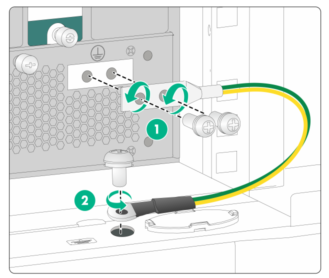
1. Loosen the two screws at the grounding holes (located at the rear panel and marked with a grounding sign) of the chassis, as shown by callout 1 in Figure 1, and then remove the grounding cable from the chassis.
2. Loosen the screws at the grounding hole on the grounding terminal of the cabinet, and remove the other end of the grounding cable (with a ring terminal), as shown by callout 2 in Figure 1.
Figure 1 Removing the grounding cable
Removing the twisted pair and optical fiber
You must remove twisted pairs and optical fibers from all the interfaces of the gateway.
|
|
NOTE: After pulling out an optical fiber from an optical transceiver module, cover the connector of the optical fiber with a dust cap to keep the connector clean. |
Repackaging the gateway accessories
Repackaging the power supply
|
|
CAUTION: Before removing a power supply, switch off the circuit breakers at the input end of all power cords, and remove all the power cords to avoid device damage and bodily injury. |
1. Prepare the packing bag and box of the power supply. Make sure the bag is clean, dry, and not damaged.
2. Remove all power supplies from the chassis, and then install filler panels to the empty slots.
For how to remove a power supply and install a filler panel, see "Replacing a power supply."
3. Put the power supply into the bag.
4. Put the packed power supply into the box. Place the power supply in a correct direction onto the foam cushion in the box; otherwise, the power supply cannot be completely seated into the foam cushion.
Repackaging the card
1. Prepare the anti-static bag and box of the card. Make sure the bag is clean, dry, and not damaged.
2. Remove the transceiver modules from the card. If no transceiver module is installed on the card, go to the next step.
For how to remove a transceiver module, see "Replacing a transceiver module."
3. Remove all cards from the chassis slots, and install blank filler panels to the empty slots.
For how to remove a card and install a blank filler panel, see "Replacing a card."
4. Put the card into the anti-static bag. The switching fabric module on an M9010, M9010-GM, M9014,or M9016-V gateway has a protection box. Put the switching fabric module into the protection box, and then put the box into the anti-static bag.
5. Put the packed card into the box, and tape the flaps of the box with packing tape. Place the card in a correct direction onto the foam cushion in the box; otherwise, the power supply cannot be completely seated into the foam cushion.
Repackaging the gateway chassis
Removing the chassis from the rack
M9000 gateways are heavy. If possible, use a mechanical lift to move the gateway.
To remove the chassis from the rack:
1. Prepare the wooden carton and packing bag of the chassis. Make sure the carton and bag are clean, dry, and not damaged.
2. Remove the top cap and side panels from the wooden carton, and put the pallet base to a secure place.
3. Use a Phillips screwdriver to loosen the screws that attach the mounting brackets to the rack.
4. Use multiple persons to slide the chassis outwards along the slide rails. When most part of the chassis is removed from the slide rails, lift up the chassis by holding the handles at the chassis sides to completely remove the chassis from the rack.
Figure 2 Removing the chassis (M9006) from the rack
5. Put the chassis onto the pallet base of the wooden carton.
Removing the air filter
1. Prepare the packing bag of the air filter. Make sure the bag is clean, dry, and not damaged.
2. Remove the air filter from the side of the chassis.
For how to remove an air filter, see "Replacing an air filter."
3. Put the air filter into the bag.
Removing cable management brackets and mounting brackets
Before repackaging the gateway chassis, remove the cable management brackets and mounting brackets from the chassis.
Removing the mounting brackets
1. Prepare the packing box of the mounting brackets. Make sure the box is clean, dry, and not damaged.
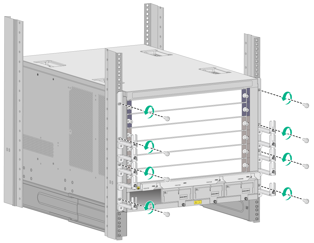
2. As shown in Figure 3, use a Phillips screwdriver to loosen the screws that attach the mounting brackets to the chassis, and then remove the mounting brackets.
Figure 3 Removing the mounting brackets from the chassis (M9006)
3. Put the mounting brackets into the box.
Removing the cable management brackets
The M9010, M9010-GM, or M9016-V gateway has two cable management brackets—the one on the chassis bottom routes power cords, and the one on the chassis top routes signal cables.
The M9006, M9014, or M9016-V gateway provides a cable management bracket at the chassis bottom to route power cords. The procedure for removing the cable management bracket on an M9006, M9014, M9016-V, and M9010 are the same.
This section takes removing a cable management bracket from an M9010 gateway as an example.
To remove the cable management brackets:
1. Prepare the packing bag of the cable management brackets. Make sure the bag is clean, dry, and not damaged.
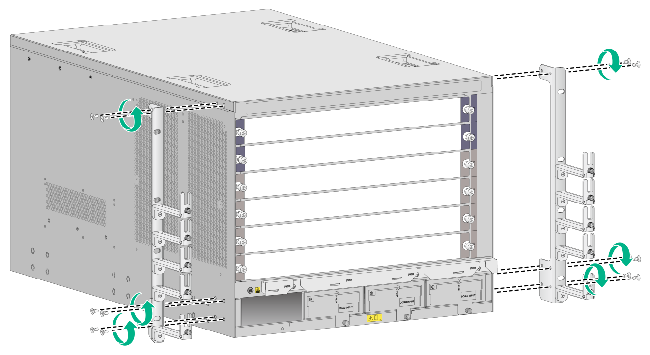
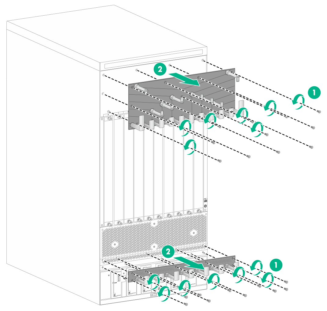
2. Use a screwdriver to loosen the screws that attach the cable management brackets to the chassis, and then remove the cable management brackets.
3. Put the cable management brackets into the bag.
Figure 4 Removing the cable management brackets (M9010)
|
(1) Loosen the screws that attach the cable management brackets to the chassis |
|
(2) Remove the cable management brackets |
Repackaging the gateway chassis
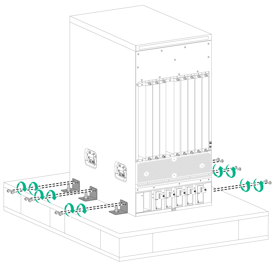
1. Align the screw holes on the two sides of the chassis bottom to the L-type brackets on the pallet base of the wooden carton.
2. Screw in the screws shipped with your gateway and fasten.
Figure 5 Installing the screws (M9010)
3. Cover the chassis with the packing bag, and then tape the bag to the base pallet.
4. Install the side panels to the base pallet.
5. Put the accessories box and mounting bracket box into the wooden carton—at the clearance between the chassis and the wooden panel.
6. Cover the foam cushion to the chassis top, and make sure the surface of the foam cushion aligns to the upper rims of the wooden carton. Cover the foam cushion in a correct direction; otherwise, the foam cushion cannot be completely placed in the wooden carton.
7. Cover the top cap to the wooden carton, and then connect the panels with corro clips on each seam.
