- Table of Contents
-
- H3C SecPath M9000 Multi Service Security Gateway Series Installation Guides-6W106
- 00-Preface
- 01-Chapter 1 Chassis views
- 01-Chapter 1 Preparing for Installation
- 02-Chapter 2 Installing the Gateway
- 03-Chapter 3 Logging in to the Gateway and Configuring Basic Settings
- 04-Chapter 4 Troubleshooting
- 06-Chapter 6 Replacing FRUs
- 07-Appendix A FRUs and Compatibility Matrixes
- 08-Appendix B Technical Specifications
- 09-Appendix C LEDs
- 10-Appendix D Slot arrangement and interface numbering
- 11-Appendix E Cables
- 12-Appendix F Cabling Recommendations
- 13-Appendix G Repackaging the Gateway
- Related Documents
-
| Title | Size | Download |
|---|---|---|
| 01-Chapter 1 Chassis views | 784.00 KB |
Chassis views
The H3C SecPath M9000 Multiservice Security Gateway Series includes the following models:
· M9006.
· M9010.
· M9010-GM.
· M9014.
· M9016-V.
Every M9000 gateway has an MPU section, interface switch module section, interface module section, service module section, switching fabric module section, power supply section, and fan tray section.
Figure 1 Front and rear views of the M9006
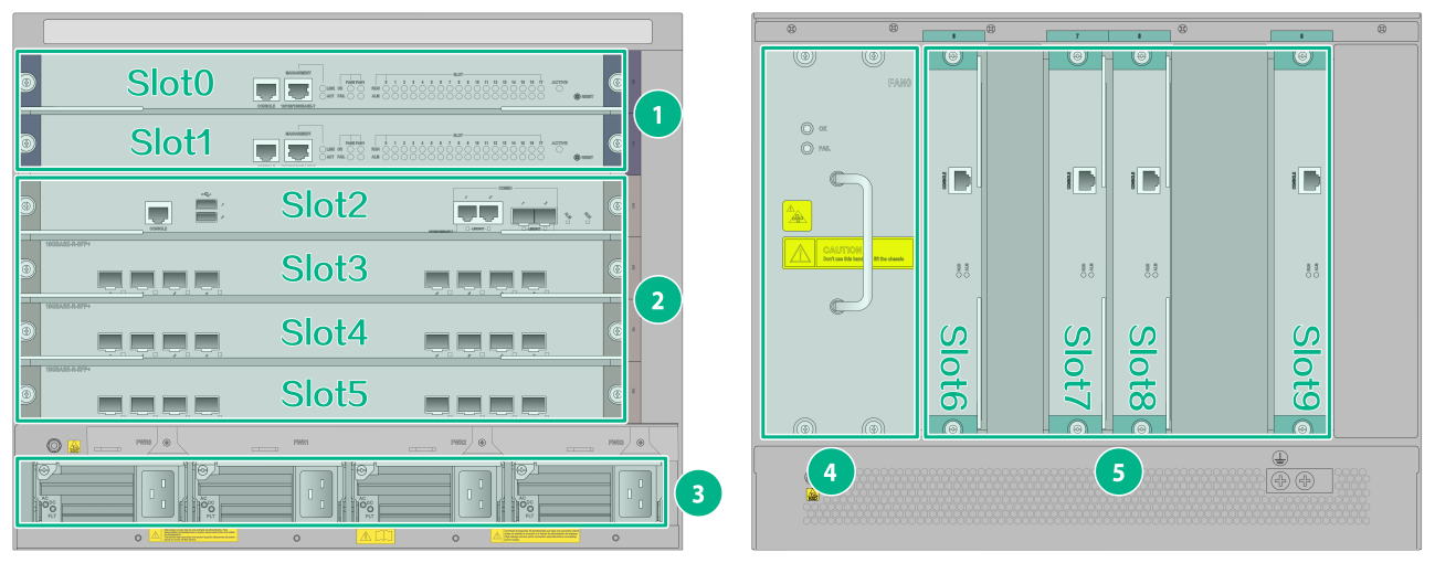
Figure 2 Front and rear views of the M9010/M9010-GM/M9016-V (M9010 as an example)
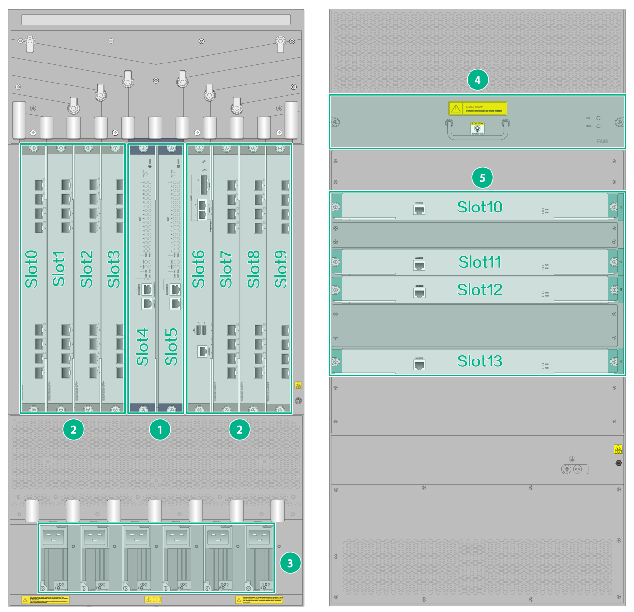
Figure 3 Front and rear views of the M9014
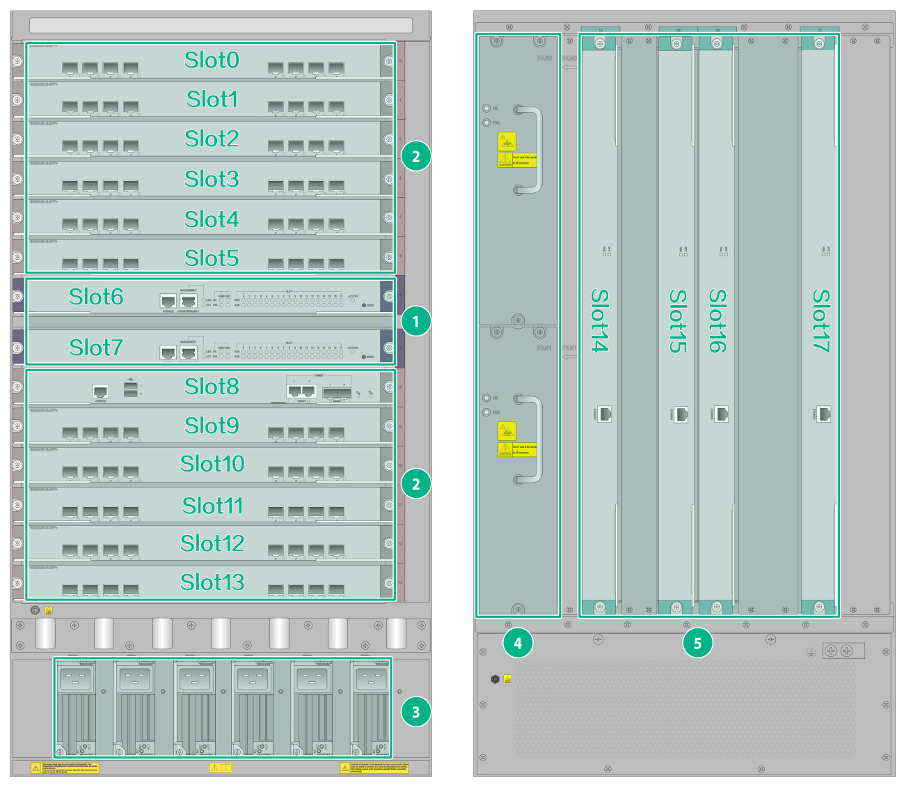
Table 1 Chassis structure
|
Section |
Remarks |
|
(1) MPU section |
MPUs are required. |
|
(2) Interface switch module, interface module, and service module section |
Interface switch modules, interface modules, and service modules are required. · An interface switch module has two slots for installing interface subcards. · The gateway supports various interface modules and service modules. Select them as required. For the available interface modules and service modules, see "Appendix A FRUs and Compatibility Matrixes." |
|
(3)Power supply section |
Power supplies are required. · The M9006 gateway has four power supply slots. · The M9010, M9010-GM, M9014, and M9016-V gateways each have six power supply slots. |
|
(4) Fan tray section |
Fan trays are required. The chassis came with a fan tray in each fan tray slot. The positions of fan trays vary by gateway model. · M9006/M9014: Fan trays are located at the left rear of the chassis. · M9010/M9010-GM/M9016-V: Fan trays are located at the upper rear of the chassis. |
|
(5) Switching fabric module section |
Switching fabric modules are required. You must install three or four switching fabric modules for the chassis. For the M9010-GM gateway, you can install only two switching fabric modules. The two lowest numbered switching fabric module slots must be installed with switching fabric modules. · For the M9006 gateway, you must install switching fabric modules in slots 6 and 7. · For the M9010, M9010-GM, and M9016-V gateways, you must install switching fabric modules in slots 10 and 11. · For the M9014 gateway, you must install switching fabric modules in slots 14 and 15. |
|
|
NOTE: · No MPUs, interface switch modules, interface modules, service modules, switching fabric modules, or power supplies are provided with the gateway. Purchase them yourself as required. · The installation procedure is the similar for the MPUs, interface switch modules, interface modules, service modules, and switching fabric modules. Unless otherwise stated, they are collectively referred to as "cards" in this document. · The gateways shown in the figures are fully configured. Install filler panels in the unused slots to prevent dust and ensure good ventilation in the gateway. |
