- Table of Contents
-
- H3C SecPath M9000 Multi Service Security Gateway Series Installation Guides-6W106
- 00-Preface
- 01-Chapter 1 Chassis views
- 01-Chapter 1 Preparing for Installation
- 02-Chapter 2 Installing the Gateway
- 03-Chapter 3 Logging in to the Gateway and Configuring Basic Settings
- 04-Chapter 4 Troubleshooting
- 06-Chapter 6 Replacing FRUs
- 07-Appendix A FRUs and Compatibility Matrixes
- 08-Appendix B Technical Specifications
- 09-Appendix C LEDs
- 10-Appendix D Slot arrangement and interface numbering
- 11-Appendix E Cables
- 12-Appendix F Cabling Recommendations
- 13-Appendix G Repackaging the Gateway
- Related Documents
-
| Title | Size | Download |
|---|---|---|
| 02-Chapter 2 Installing the Gateway | 2.50 MB |
Confirming installation preparations
Attaching slide rails to the rack
Installing cage nuts for attaching mounting brackets
Attaching cable management brackets and mounting brackets to the chassis
Installing cable management brackets
(Optional) Installing air filters
Attaching air filters to an M9006/M9014 gateway
Attaching air filters to an M9010/M9010-GM/M9016-V gateway
Mounting the gateway in the rack
Installing an interface subcard
Installing an XFP/SFP+/SFP/QSFP+/QSFP28 transceiver module
Connecting twisted pair cables
Connecting a high-voltage DC power cord
Installing the gateway
|
|
IMPORTANT: Keep the packages of the gateway and the components secure for repackaging. |
Confirming installation preparations
Before you install the gateway, verify that:
· You have read the chapter "Preparing for installation" carefully and the installation site meets all the requirements.
· A 19-inch rack has been installed. For how to install a rack, see the rack installation guide.
· The rack is sturdy and securely grounded.
· The rack has enough space to install the gateway and no debris exists inside or around the rack.
· The mounting position of the gateway on the rack has been identified. As a best practice, install the gateway at the bottom of the rack.
· The total height of the devices to be installed in the rack is no higher than the available installation height of the rack and enough clearance is reserved for cable routing. Make sure the heaviest device is placed at the bottom of the rack.
· The gateway is ready for installation and has been carried to a place near the rack and convenient for moving.
Attaching slide rails to the rack
If the rack has slide rails installed, skip this section.
Before you attach slide rails to the rack, verify that the slide rails can support the weight of the gateway. For the weights of the device, see "Appendix B Chassis views and technical specifications."
As a best practice, order H3C slide rail LSTM2KSGD0. The slide rail has an adjustment range of 500 mm (19.69 in) to 800 mm (31.50 in).
The M9000 multiservice gateway series includes multiple models with different heights. Plan the installation location for the chassis and slide rail installation location within the rack based as needed. For the dimensions of the device, see "Appendix B Chassis views and technical specifications."
Slide rail installation varies by rack type. The following installation procedure is for your reference only.
1. Read the signs on the slide rails (see Table 1) to identify the left and right slide rails.
Figure 1 Right slide rail
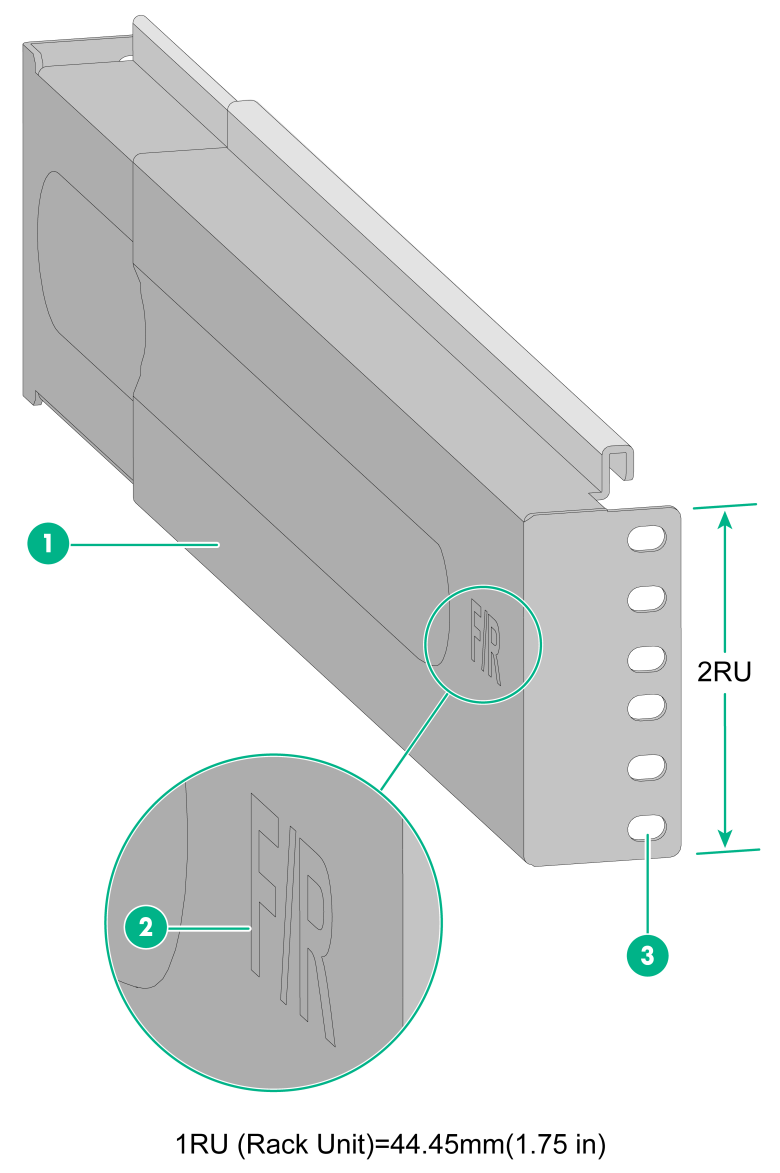
|
(1) Guide rail |
(2) Sign |
(3) Installation hole |
Table 1 Description of signs on the slide rails
|
Sign |
Meaning |
Remarks |
|
F/L |
Front end of the left slide rail |
Mount this end to the front left rack post. |
|
F/R |
Front end of the right slide rail |
Mount this end to the front right rack post. |
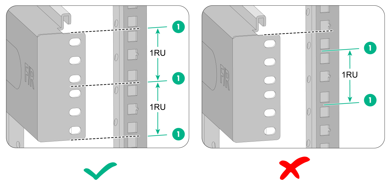
2. Mark the slide rail installation positions on the rack posts.
The square holes on the rack post are divided into rack units (RUs). One RU has two standard installation holes and one auxiliary installation hole in the middle. The space between a standard installation hole and an auxiliary installation hole is wider than the space between two adjacent standard installation holes.
a. Align the bottom edge of the slide rail with the middle of the narrower metal area between holes, as shown in Figure 2.
b. Mark the uppermost and the lowermost installation holes on each rack post. Each rack post requires six screws to attach the slide rail.
Figure 2 Locating the cage nut installation positions on the rack post
|
(1) Middle of the narrower metal area between holes |
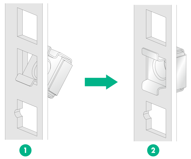
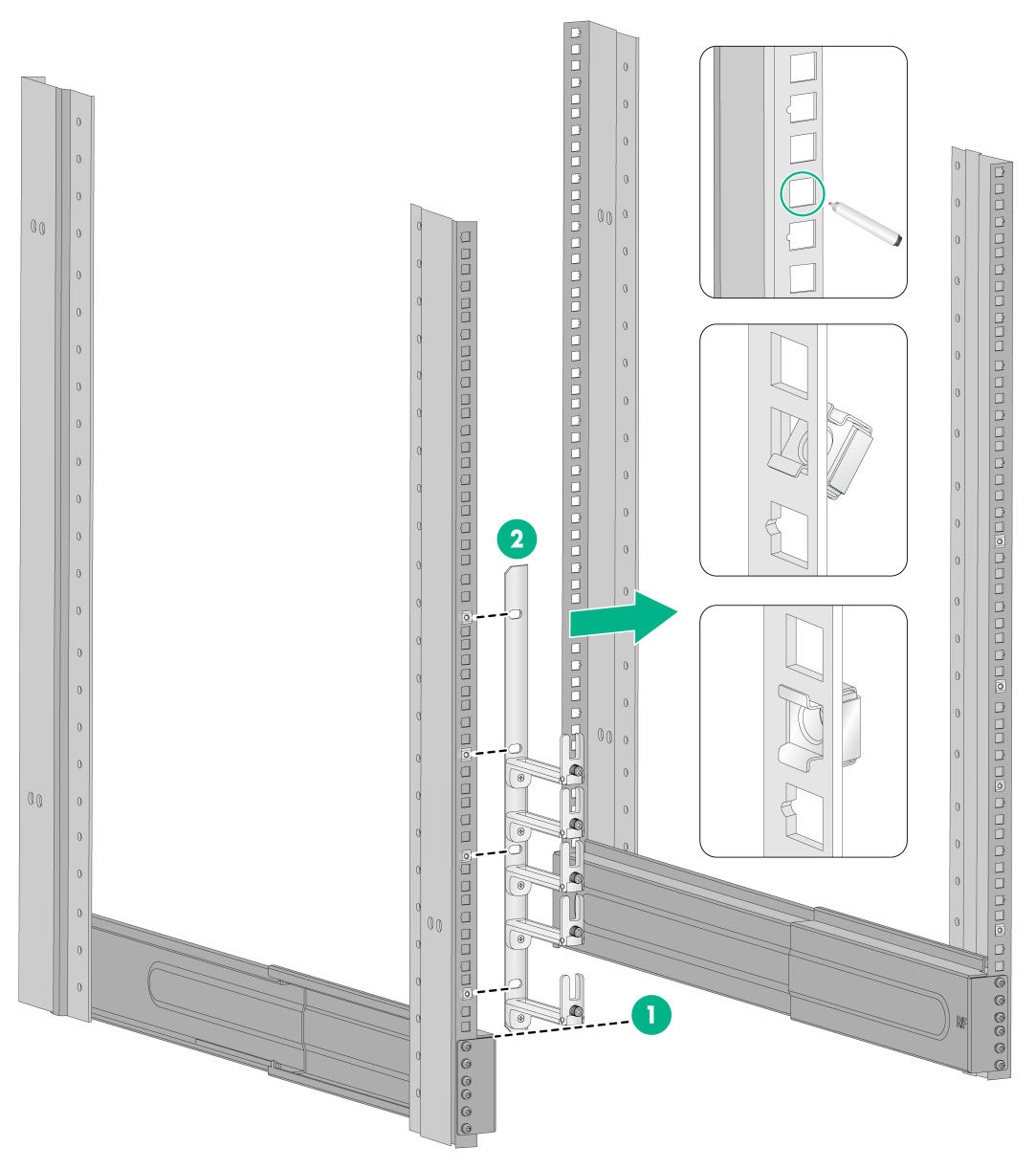
3. Install six cage nuts in the square holes on each rack post, as shown in Figure 3.
Figure 3 Installing a cage nut
4. Align the installation holes on the front end of the slide rail with the cage nuts on the front rack post, and attach them with screws, as shown in Figure 4.
Figure 4 Attaching the slide rail to the rack
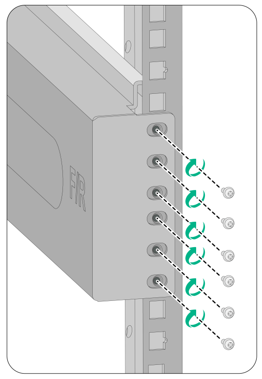
5. Keep the slide rail horizontally and adjust its length until the installation holes on the rear end of the slide rail touch the cage nuts on the rear rack post. Then fasten a screw in each installation hole.
Install a screw in each mounting hole of the slide rail to ensure its weight bearing capacity.
6. Repeat steps 4 and 5 to install the other slide rail. Make sure the two slide rails are at the same height so that the gateway can be placed on them horizontally.
Installing cage nuts for attaching mounting brackets
1. Align the bottom edge of a mounting bracket with the weight-bearing surface of a slide rail.
2. Determine and mark the cage nut installation holes on the rack post. Each installation hole on the mounting bracket requires a cage nut.
3. Install cage nuts on the marked square holes on the front rack post.
4. Repeat steps 1, 2, and 3 to install cage nuts on another front rack post.
Figure 5 Installing cage nuts (M9006 gateway as an example)
|
(1) The bottom edge of the mounting bracket aligns with the weight-bearing surface of the slide rail |
|
(2) Install the cage nuts |
Attaching cable management brackets and mounting brackets to the chassis
Before installing the gateway in the rack, attach the shipped cable management brackets and mounting brackets to the gateway. Cable management brackets (signal cable and power cord management brackets) are used for cabling the gateway, and mounting brackets are used for attaching the chassis to the rack.
Installing cable management brackets
The M9010, M9010-GM, and M9016-V gateways each have two cable management brackets—the signal cable management brackets are installed at the upper part of the gateway, and the power cord management brackets are installed at the lower part of the gateway. They are installed in the same way. For more information, see Figure 6.
The M9006 and M9014 gateways come with the signal cable management brackets secured to the mounting brackets. The power cord management bracket of the M9006 gateway has a slightly different structure than M9014, and is installed in a similar procedure. For more information, see Figure 7.
The power cord management bracket installation procedure for the M9014, M9010, M9016-V, and M9010-GM is the same.
To install a cable management bracket:
1. Unpack the cable management bracket from the accessory kit package.
2. Place the cable management bracket against the installation position on the chassis, and align the screws with the mounting holes on the chassis, as shown in Figure 6.
3. Fasten the screws to secure the cable management bracket to the chassis.
Figure 6 Attaching cable management brackets to an M9010/M9010-GM/M9014/M9016-V gateway (M9010 as an example)

|
(1) Place the cable management bracket against the installation position on the chassis |
|
(2) Screw holes for installing the cable management bracket |
|
(3) Screws for attaching the cable management bracket to the chassis |
|
(4) Signal cable management bracket (installed at the upper part of the chassis) |
|
(5) Power cord management bracket (installed at the lower part of the chassis) |
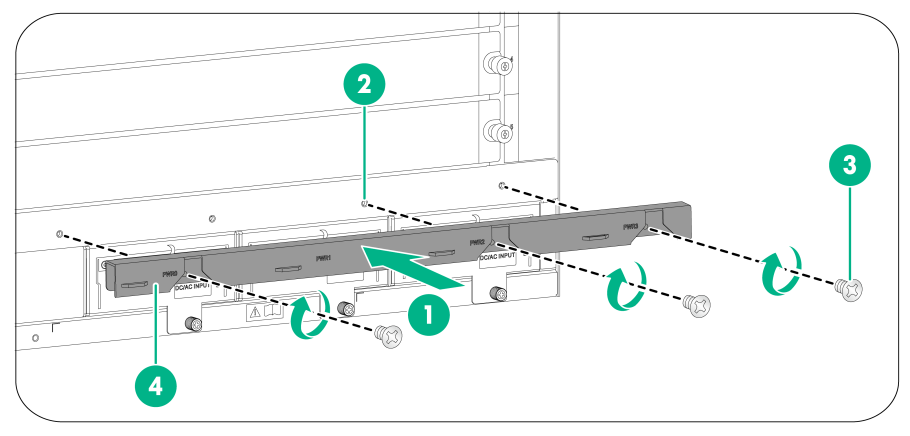
Figure 7 Attaching the power cord management bracket to an M9006 gateway
|
(1) Place the cable management bracket against the installation position on the chassis |
|
(2) Screw holes for installing the cable management bracket |
|
(3) Screws for attaching the cable management bracket to the chassis |
|
(4) Power cord management bracket |
Installing mounting brackets
Before installing the gateway to the rack, install the mounting brackets to the chassis. Marks L and R are printed inside the mounting brackets to distinguish between the left and right mounting brackets.
To install the mounting brackets, face the front of the gateway, and attach the left and right mounting brackets to the two sides of the gateway, as shown in Figure 8.
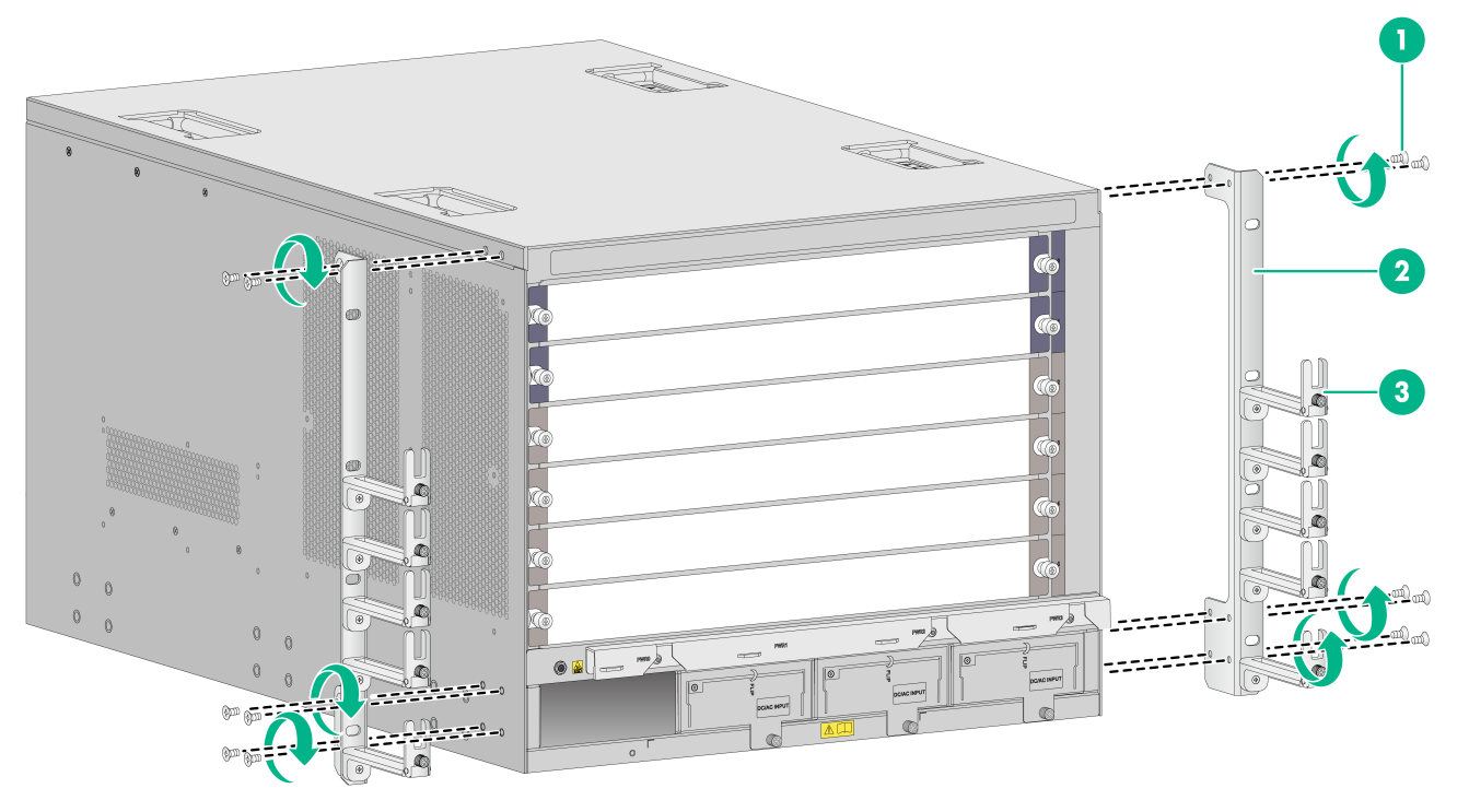
Figure 8 Installing the mounting brackets (M9006 gateway as an example)
|
(1) Screws for attaching the mounting brackets to the chassis |
(2) Mounting brackets |
|
(3) Signal cable management brackets |
|
(Optional) Installing air filters
Air filters are installed at the air inlet vents to prevent dust from entering the chassis. If you have ordered air filters, install the air filters before mounting the gateway to the rack.
Attaching air filters to an M9006/M9014 gateway
Air filters of an M9006/M9014 gateway are installed at the left of the chassis. The air filter installation procedures on an M9006 and M9014 are the same.
To install an air filter on an M9006/M9014 gateway:
1. Put the air filter near the air inlet vents on the left of the chassis and insert the poisoning pins on the air filter into the corresponding holes on the chassis.
2. Insert the screws into the screw holes on the air filter, and fasten them with a Phillips screwdriver.
Figure 9 Attaching air filters to an M9006/M9014 gateway (M9006 as an example)
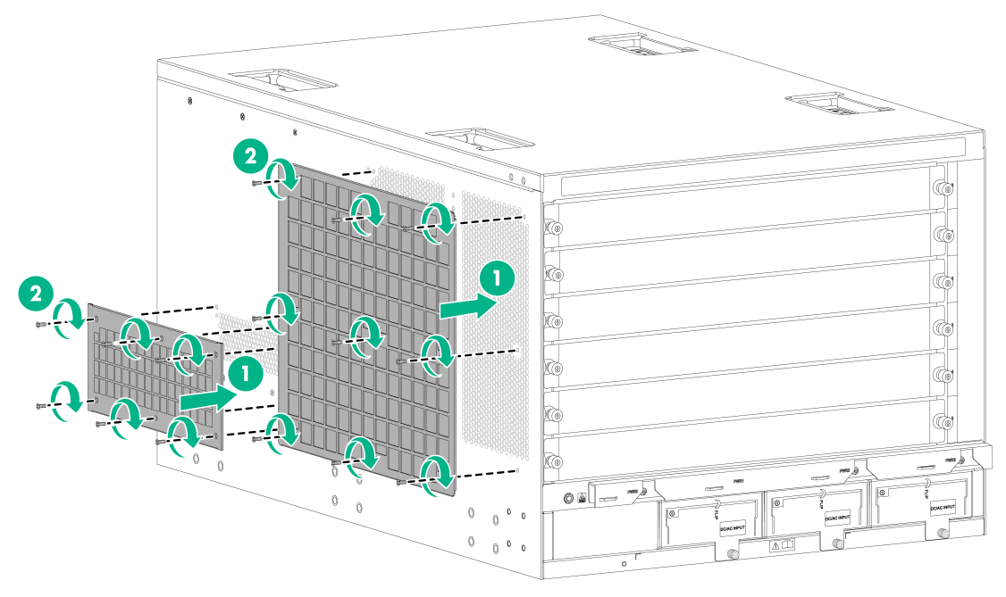
Attaching air filters to an M9010/M9010-GM/M9016-V gateway
The air filter of an M9010, M9010-GM, or M9016-V gateway is installed at the lower part of the chassis front.
To install an air filter on an M9010 gateway:
1. Put the air filter near the air inlet vent on the lower part of the chassis front and insert the poisoning pins on the air filter into the corresponding holes on the chassis.
2. Insert the screws into the screw holes on the air filter, and fasten them with a Phillips screwdriver.
Figure 10 Attaching an air filter to an M9010/M9010-GM/M9016-V gateway

|
|
TIP: · Install the power cord management bracket before you install an air filter for the M9010, M9010-GM, or M9016-V gateway. · Clean the air filter every three months to ensure correct ventilation and heat dissipation of the gateway. |
Mounting the gateway in the rack
|
|
WARNING! To avoid device damage or even bodily injury, do not hold the handle of a fan tray or power supply, air vents, or the handle on the rear panel of the chassis to move the gateway. |
To mount the gateway in the rack:
1. Move the chassis to face the rear of the chassis towards the front of the rack.
2. Use at least two people to lift the gateway by holding the chassis handles or supporting the bottom of the chassis until the bottom of the gateway is a little higher than the slide rails on the rack.
As a best practice, use a mechanical lift for moving your gateway.
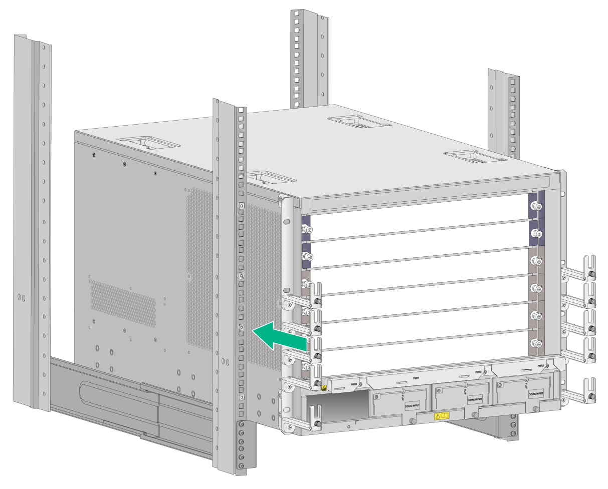
3. Place the gateway on the slide rails and slide the gateway along the slide rails until the mounting brackets on the gateway touch the front rack posts, as shown in Figure 11.
After placing the switch on the slide rails, do not leave go of your hands immediately because this might tip the switch, damaging the switch or even causing bodily injury.
Figure 11 Placing the chassis on the rack (M9006)
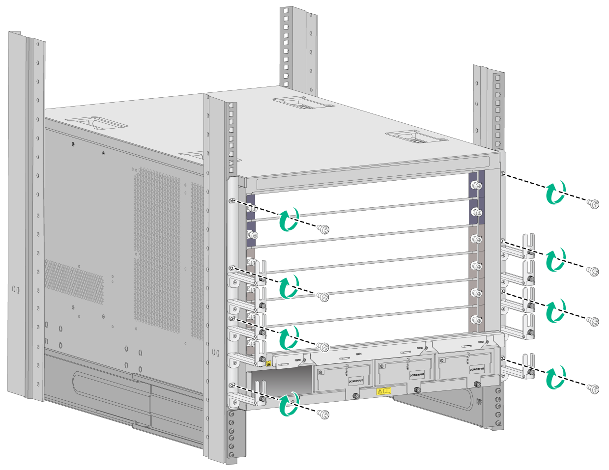
4. Use the screws to attach the mounting brackets to the rack.
If the mounting holes in the mounting brackets cannot align with the cage nuts on the rack, verify that the bottom edge of the slide rail aligns with the middle of the narrower metal area between holes and that the cage nuts are installed in the correct holes.
Figure 12 Securing the chassis to the rack (M9006 as an example)
Grounding the gateway
|
|
CAUTION: · Before you use the gateway, ground the gateway correctly. · Use the grounding cable (yellow-green grounding cable) that comes with your gateway. · Make sure the grounding terminal of the rack is connected to the grounding strip in the equipment room. Do not connect it to a fire main or lightning rod. |
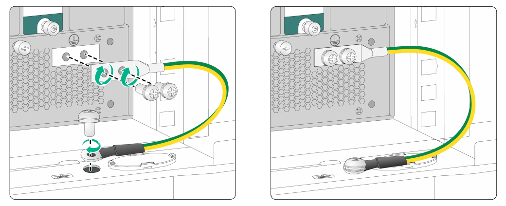
To ground the gateway:
1. Remove the grounding screws from the grounding holes at the rear of the chassis.
2. Use the grounding screws to attach the two-hole grounding lug of the grounding cable to the chassis.
3. Remove the grounding screw from the grounding hole of the cabinet's grounding terminal.
4. Use the grounding screw to attach the ring terminal of the grounding cable to the grounding terminal of the cabinet.
Figure 13 Grounding the gateway
Installing FRUs
Attaching an ESD wrist strap
|
|
CAUTION: Use a multimeter to check the resistance value of the ESD wrist strap. Make sure the resistance between the human body and the ground is between 1 to 10 megaohms. |
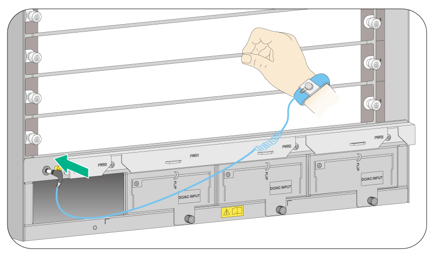
The gateway comes with an ESD wrist strap. To minimize ESD damage to electronic components, wear the ESD wrist strap and make sure it is reliably grounded when installing modules.
To attach an ESD wrist strap:
1. Make sure the gateway is correctly grounded. For how to ground your gateway, see "Grounding the gateway."
2. Put on the wrist strap.
3. Tighten the wrist strap to keep good skin contact.
4. Insert the grounding terminal of the ESD wrist strap into the ESD port on the gateway chassis.
Figure 14 Attaching an ESD wrist strap (M9006 as an example)
Installing a card
|
|
IMPORTANT: · The gateway comes with no blank filler panels on some card slots. The figures in this document are for illustration only. · The switching fabric modules of the M9010, M9010-GM, and M9014 have protection boxes when shipped. Before you install a switching fabric module, pull the ejector levers on the module outwards, and then pull the module out of the protection box. · Only the NSQM1AIASKA1 security engine module and NSQM1SSICASK1 security situation intelligent computer node module each occupy two module slots. Before installing these modules, remove the filler panel from the target slot and upper (left) adjacent slot. · To ensure adequate heat dissipation, install filler panels in unused slots in time. |
The installation procedures for MPUs, interface switch modules, interface modules, service modules, and switching fabric modules are the same. Unless otherwise stated, MPUs, interface switch modules, interface modules, service modules, and switching fabric modules are collectively referred to as "cards" in this document.
These cards are either horizontally oriented or vertically oriented. When installing a card in a horizontal slot, make sure its PCB faces up. When installing a card in a vertical slot, make sure its PCB faces left.
This section takes installing a horizontally oriented card as an example.
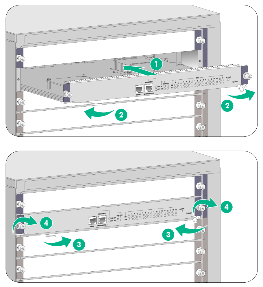
To install a horizontally oriented card:
1. Select the slot to install the card, and remove the blank filler panel (if any) from the slot.
2. Hold the card by the front panel with one hand and support the card bottom with the other. Slide the card steadily into the slot along the guide rails, as shown in callout 1 on Figure 15.
3. When most part of the card is inserted in the slot, press the ejector levers on the card outward, as shown in callout 2 on Figure 15.
4. Push the card until the positioning pin on card touches the hole on the chassis.
5. As shown in callout 3 on Figure 15, press the ejector levers inward until the ejector levers touch the panel tightly and the card seats into the backplane
6. As shown in callout 4 on Figure 15, fasten the captive screws on the card.
Installing an interface subcard
|
|
CAUTION: An interface subcard cannot be hot swapped. To install an interface subcard on the gateway, first install it on an interface switch module and then install the interface switch module on the gateway. |
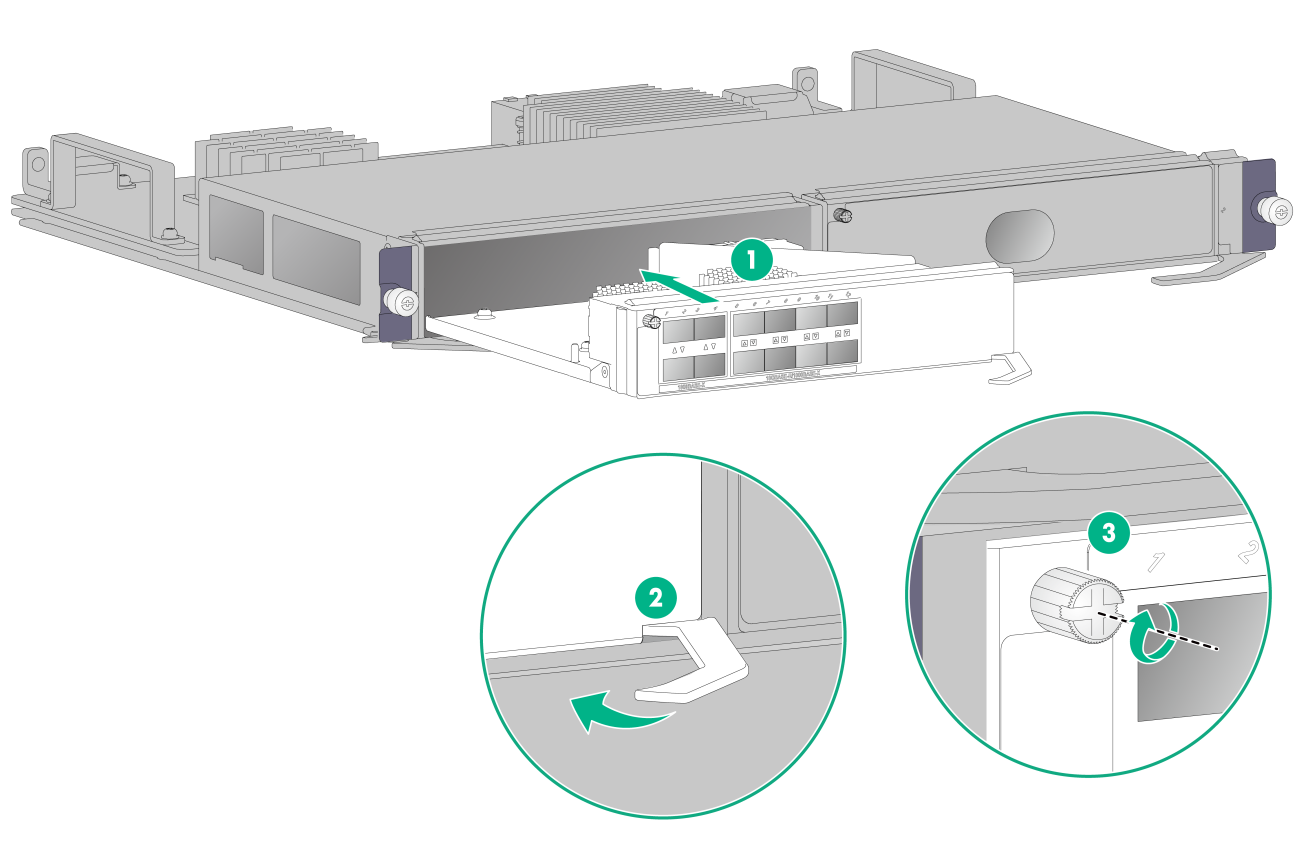
To install an interface subcard:
1. Remove the filler panel from the target slot on the interface switch module.
Keep the removed filler panel secure.
2. Open the ejector lever on the interface subcard and then push the subcard slowly into the slot along the guide rails until you cannot push it any further.
3. Close the ejector lever until the subcard is securely seated in the slot.
4. Use a Phillips screwdriver to fasten the captive screw on the interface subcard.
Figure 16 Installing an interface subcard on an interface switch module
5. Install the interface switch module on the device. For the detailed installation procedure, see "Installing a card."
Installing a power supply
|
|
CAUTION: · Do not install AC power supplies and DC power supplies on the same gateway. · Select power supplies according to the power supply at the installation site. · Provide a circuit breaker for each power supply and make sure the circuit breaker is off before installing the power supply. · To ensure adequate heat dissipation, install filler panels in unused power supply slots in time. |
The installation procedure is the same for AC, DC, and high-voltage DC power supplies. This section uses an AC power supply as an example.
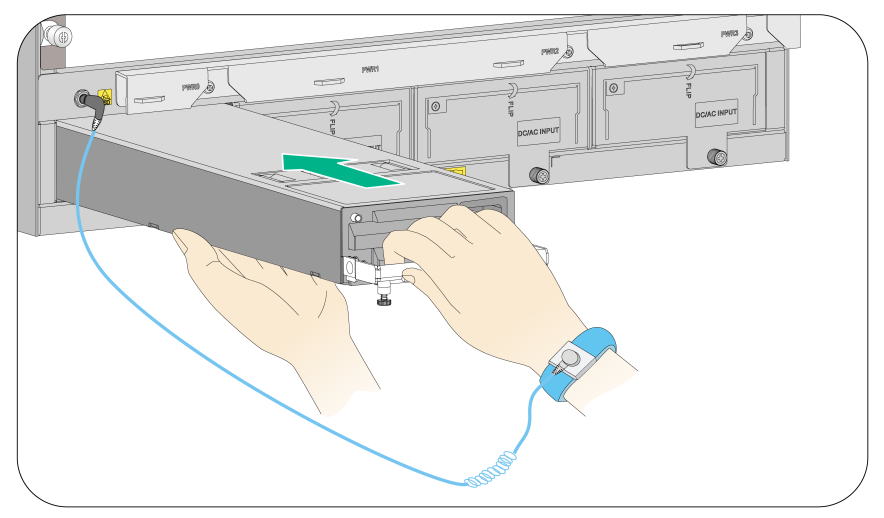
To install the power supply:
1. Use a Phillips screwdriver to loosen the captive screws on the blank filler panel (if any) to remove the blank filler panel.
2. Follow the installation graph printed on the blank filler panel of the power supply to install the power supply in a correct direction:
a. Grasp the handle of the module with one hand and support the module bottom with the other.
b. Push the power supply along the guide rails into the slot until it has firm contact with the slot.
For vertical slot installation, see Figure 17. For horizontal slot installation, see Figure 18.
3. Press the handle inward until the handle seats into the slot.
4. Use a Phillips screwdriver to fasten the captive screw on the handle to attach the power supply.
Figure 17 Installing a power supply in a vertical slot (M9010/M9010-GM/M9014/M9016-V)
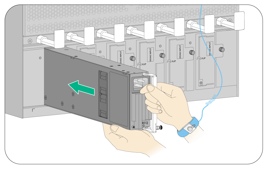
Figure 18 Installing a power supply in a horizontal slot (M9006)
|
|
NOTE: The device comes with no filler panels in some power supply slots. The figures are for illustration only. |
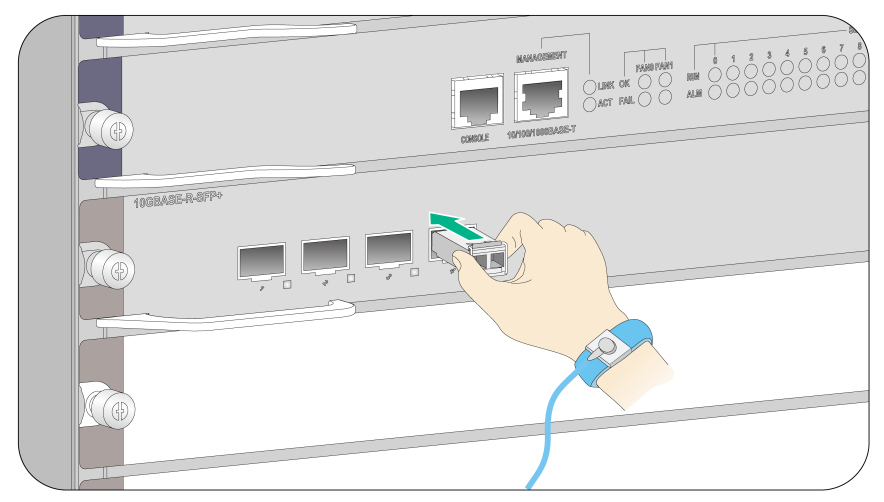
Installing an XFP/SFP+/SFP/QSFP+/QSFP28 transceiver module
|
|
CAUTION: · To avoid component damage, read this section carefully before installing a transceiver module. · Do not remove the dust plug from a transceiver module before connecting an optical fiber. · Remove the optical fiber, if any, from a transceiver module before installing it. |
To install a transceiver module:
1. Unpack the module. Do not touch the golden finger of the transceiver module.
2. Remove the dust cover from the fiber port on the chassis.
3. Remove the dust plug from the transceiver module.
4. Pivot the clasp of the transceiver module up. Holding the transceiver module, gently push the module into the slot until it has firm contact with the slot (when the bottom spring tabs catch in the slot).
¡ For a QSFP+/QSFP28 module that uses a plastic pull latch, skip this step. QSFP+/QSFP28 modules use either a metal or plastic pull latch. They are installed in the same way except that you must pivot the clasp up for the module that uses a metal pull latch.
¡ For an SFP+ module, press the module down against the upward force of the bottom spring tab so you can push the module straight into the port.
¡ If you cannot hold the module by its two sides because of high module density, press the module on its head end to push it in.
Figure 19 Installing an XFP/SFP+/SFP/QSFP+/QSFP28 transceiver module
Installing a CFP module
|
|
CAUTION: · Read the following instructions before installing a CFP module. Failure to follow these instructions might cause damage to the CFP module. · Do not remove the dust plug from the CFP module before connecting an optical fiber. · Before installing a CFP module, remove the optical fiber, if any, from it. |
To install a CFP module:
1. Wear an ESD wrist strap and make sure it makes good skin contact and is correctly grounded. For more information, see "Attaching an ESD wrist strap."
2. Unpack the CFP module. Do not touch the golden finger of the module.
3. Gently push the CFP module into the slot until it has firm contact with the slot, and then fasten the captive screws on the CFP module.
Figure 20 Installing a CFP module
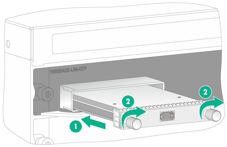
|
(1) Gently push the CFP module into the slot |
(2) Fasten the captive screws on the CFP module |
4. Connect the optical fiber to the CFP module. For information about connecting optical fibers, see "Connecting optical fibers."
Connecting networking cables
Connecting twisted pair cables
The 10/100Base-TX ports, 1000Base-T ports, and 10GBase-T ports on your gateway use RJ-45 connectors and support MDI/MDI-X auto-sensing. Use category-6A or category-7 twisted pair cables to connect 10GBase-T ports and category-5 or above to connect other ports. For more information about twisted pair cables, see "Appendix E Cables."
To connect a 10/100Base-TX, a 1000Base-T port, or a 10GBase-T port to a peer device:
1. Plug one end of a twisted pair cable into the RJ-45 Ethernet port on the gateway.
2. Plug the other end of the twisted pair cable into the RJ-45 Ethernet port of the network access device.
3. Examine the port LEDs to verify the connection after the gateway is powered on.
For more information about the LED status, see "Appendix C LEDs."
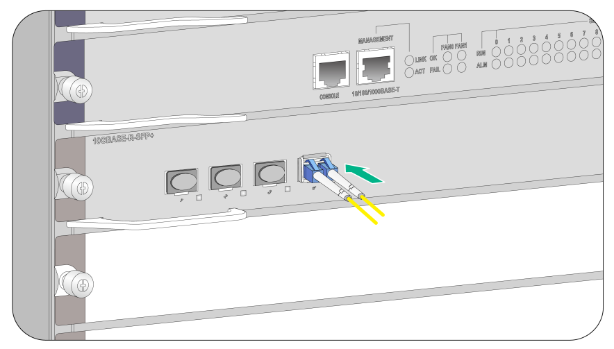
Connecting optical fibers
|
|
WARNING! To avoid injury to your eyes, do not stare at the optical ports and optical fiber connectors when connecting optical fibers. |
You can install a transceiver module (see "Installing an XFP/SFP+/SFP/QSFP+/QSFP28 transceiver module and Installing a CFP module") in a fiber port and use optical fibers to connect the port to the network. For more information about optical fibers, see "Appendix E Cables."
To connect a fiber port to a peer device through optical fibers:
1. Remove the dust cover of the optical fiber connector, and clean the end of the optical fiber.
2. Plug one end of the optical fiber into the transceiver module on the gateway, and plug the other end into the transceiver module in the peer device.
3. Examine the port LEDs to verify the connection after the gateway is powered on.
For more information about the LED status, see "Appendix C LEDs."
|
|
NOTE: For the QSFP+/QSPF28 transceiver module, you do not need to differentiate between the transmitter (TX) and receiver (RX) ports. For other types of transceiver modules, the Tx port on one end must connect to the RX port on the other end. |
Figure 21 Connecting a fiber connector to the transceiver module (LC connector)
|
|
TIP: After you connect the gateway into the network, use the ping or tracert command to test the network connectivity. For more information about these commands, see the configuration guides that come with your gateway. |
Connecting power cords
|
|
WARNING! Before you connect the power cord to a power supply, make sure the circuit breaker is switched off. |
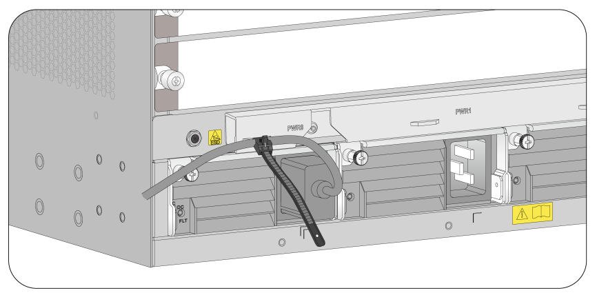
Connecting an AC power cord
1. Insert the power cord plug into the power receptacle of the power supply.
2. Use a cable tie to secure the power cord to the cable management bracket.
3. Plug the other end of the power cord to the AC power receptacle of the power source.
Figure 22 Securing the AC power cord (M9006 as an example)
Connecting a DC power cord
1. Insert the power cord plug into the power receptacle of the power supply.
2. Fasten the screw to secure the power cord.
Figure 23 Connecting the power cord (M9010 as an example)
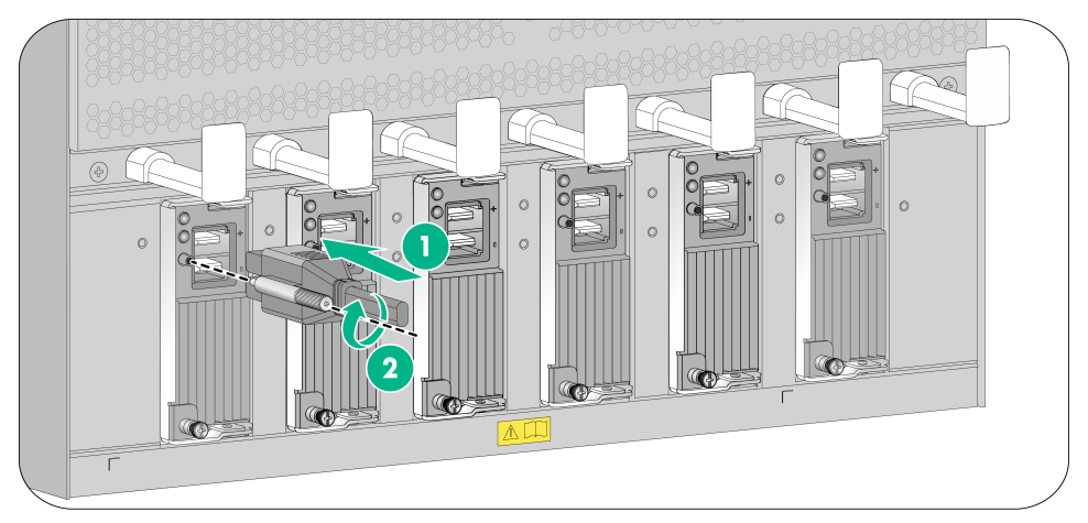
|
(1) Insert the power cord plug into the power supply |
(2) Fasten the screw |
3. Use a cable tie to secure the power cord to the cable management bracket. For more information, see Figure 22.
4. Connect the other end of the power cord to the power source.
¡ Connect the blue DC power cord marked with –48V to the negative terminal (–48V) on the power source.
¡ Connect the black DC power cord with RTN end to the positive terminal (RTN).
Connecting a high-voltage DC power cord
The connection procedure for a high-voltage DC power cord is the same as that for an AC power cord. To connect a high-voltage DC power cord, see "Connecting an AC power cord."
Verifying the installation
Table 2 Post-installation checklist
|
Item |
Requirements |
|
Installation site |
· No condensation on the surface of the gateway or inside of the gateway. · Keep the gateway clean and dust free. · No packing boxes, packing bags or other packing materials left in the installation site. · Keep the air inlet and outlet vents of the gateway free of obstruction. |
|
Gateway |
· All modules are installed correctly. · No slot is empty. Each is installed with a module or filler panel, · Fan trays are installed correctly. |
|
Cables |
· The gateway is grounded reliably with the provided grounding cable. Both ends of the grounding cable are securely connected. · No switch or fuse is installed on the grounding cable. · The power cords are connected reliably and no short circuit has occurred in power input and output. · Power cords, grounding cables and fiber cables are routed and bound separately. · The cables are bound neatly with cable ties at an even distance. · The cable labels are correct, clear, and affixed to the cable in the same direction. |
|
Electricity safety |
· A circuit breaker is provided for each power input line. · The circuit breaker is switched off before you connect the power cord to a power module, |
Power-on check
|
|
WARNING! Locate the emergency power-off switch in the room before power-on so you can quickly shut power off when an electrical accident occurs. |
|
|
CAUTION: Before powering on the gateway, make sure all fan trays are present. |
Power-on check flowchart
Figure 24 Power-on check flowchart
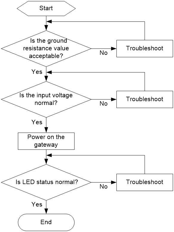
The gateway provides LEDs for modules installed on the gateway to indicate their operating status. For more information about LEDs, see "Appendix C LEDs."
