- Table of Contents
-
- H3C SecPath M9000 Multi Service Security Gateway Series Installation Guides-6W106
- 00-Preface
- 01-Chapter 1 Chassis views
- 01-Chapter 1 Preparing for Installation
- 02-Chapter 2 Installing the Gateway
- 03-Chapter 3 Logging in to the Gateway and Configuring Basic Settings
- 04-Chapter 4 Troubleshooting
- 06-Chapter 6 Replacing FRUs
- 07-Appendix A FRUs and Compatibility Matrixes
- 08-Appendix B Technical Specifications
- 09-Appendix C LEDs
- 10-Appendix D Slot arrangement and interface numbering
- 11-Appendix E Cables
- 12-Appendix F Cabling Recommendations
- 13-Appendix G Repackaging the Gateway
- Related Documents
-
| Title | Size | Download |
|---|---|---|
| 01-Chapter 1 Preparing for Installation | 373.71 KB |
Preparing for installation
Safety recommendations
To avoid bodily injury and equipment damage, read all safety recommendations carefully before installation. Note that the recommendations do not cover every possible hazardous condition.
General safety recommendations
· Keep the gateway clean and dust-free.
· Do not place the gateway on a moist area, and avoid liquid flowing into the gateway.
· Make sure the ground is dry and flat and anti-slip measures are in place.
· Keep the gateway and installation tools away from walk areas.
· Do not wear loose clothing, jewelry (for example, necklace) or any other things that could get caught in the chassis when you install and maintain the gateway.
Electricity safety
· Clear the work area of possible electricity hazards, such as ungrounded power extension cables, missing safety grounds, and wet floors.
· Locate the emergency power-off switch in the room before installation so you can quickly shut power off when an electrical accident occurs.
· Unplug all external cables, including power cords, before moving the chassis.
· Do not work alone when the gateway has power.
· Always verify that power has been disconnected from a circuit.
Moving safety
|
|
CAUTION: Hold the carrying handles of the chassis to move the chassis. Do not move the chassis with any other handles than the carrying handles, for example, a fan tray handle, a power supply handle, the chassis air vents, or a handle at the chassis rear. Any attempt to move the gateway with these parts might cause equipment damage and even bodily injury. |
The device is heavy and large. When you move the gateway, follow these guidelines:
· Remove all external cables, including power cords, before moving the chassis.
· Use multiple people to move it. You can use a mechanical lift as needed.
· Apply force evenly and slowly when moving the chassis. Do not use excessive force when lifting or placing down the chassis.
ESD prevention
To prevent the electric component from being damaged by electrostatic discharge (ESD), follow these guidelines:
· Ground the gateway correctly. For how to ground your gateway, see "Grounding the gateway."
· Always wear an ESD wrist strap and make sure it is correctly grounded when installing FRUs. For how to use an ESD wrist strap, see "Attaching an ESD wrist strap."
· Hold a PCB by its edges. Do not touch any electronic components or printed circuit.
· Put cards away in antistatic bags for future use.
Laser safety
|
|
WARNING! · Disconnected optical fibers or transceiver modules might emit invisible laser light. Do not stare into beams or view directly with optical instruments when the router is operating. · Before you remove the optical fiber connector from a fiber port, execute the shutdown command in interface view to shut down the port. |
|
|
CAUTION: · Insert dust caps into open optical fiber connectors to protect them from contamination and ESD damage. · Insert dust plugs into open fiber ports and transceiver module ports to protect them from contamination and ESD damage. |
Examining the installation site
The gateway must be used indoors. To ensure the correct operation and long service life of your gateway, the installation site must meet the requirements in this section.
Weight support
Make sure the floor can support the total weight of the rack, chassis, and accessories. Additionally, the floor loading plan must also consider system expansion, such as adding more cards. For more information, see "Appendix B Chassis views and technical specifications."
Temperature
|
CAUTION: If condensation occurs on the chassis when you move it from a lower temperature to a higher temperature, dry the chassis before powering it on to avoid short circuits. |
|
|
CAUTION: If condensation occurs on the chassis when you move it from a lower temperature to a higher temperature, dry the chassis before powering it on to avoid short circuits. |
To ensure the correct operation of the gateway, make sure the room temperature meets the requirements in Table 1.
Table 1 Temperature requirements
|
Temperature |
Range |
|
Operating temperature |
0°C to 45°C (32°F to 113°F) |
|
Storage temperature |
–40°C to +70°C (–40°F to +158°F) |
Humidity
Maintain appropriate humidity in your equipment room, as described in Table 2.
· Lasting high relative humidity tends to cause poor insulation, electricity leakage, mechanical property change of materials, and corrosion of metal parts.
· Lasting low relative humidity is likely to result in loose screws due to washer contraction, and even electrostatic discharge (ESD), which causes the circuits to fail.
|
Humidity |
Range |
|
Operating humidity |
5% RH to 95% RH, noncondensing |
|
Storage humidity |
5% RH to 95% RH, noncondensing |
Cleanliness
Dust buildup on the chassis might result in electrostatic adsorption, which causes poor contact of metal components and contact points. In the worst case, electrostatic adsorption can cause communication failure.
Table 3 Dust concentration limit in the equipment room
|
Substance |
Concentration limit (particles/m3) |
|
Dust particles |
≤ 3 x 10⁴ (No visible dust on desk in three days) |
|
NOTE: Dust particle diameter ≥ 5 µm |
|
The equipment room must also meet limits on salts, acids, and sulfides to eliminate corrosion and premature aging of components, as shown in Table 4.
Table 4 Harmful gas limits in an equipment room
|
Gas |
Max. (mg/m3) |
|
SO2 |
1.0 |
|
H2S |
0.5 |
|
NH3 |
3.0 |
|
Cl2 |
0.3 |
|
NO2 |
1.0 |
EMI
Electromagnetic interference (EMI) might be coupled from the source to the gateway through the following coupling mechanisms:
· Capacitive coupling
· Inductive coupling
· Radiative coupling
· Common impedance coupling
· Conductive coupling
To prevent EMI, take the following actions:
· Filter interference from the power grid.
· Keep the gateway grounding facilities away from grounding and lightning protection facilities of other devices.
· Keep the gateway far away from radio transmitting stations, radar stations, and high-frequency devices to make sure the EMI levels do not exceed the compliant range.
· Use electromagnetic shielding, for example, shielded interface cables, when necessary.
Lightning protection
To better protect the device from lightning, follow these guidelines:
· Ensure that the grounding cable of the chassis is reliably grounded.
· Ensure that the grounding point of the AC power receptacle is reliably grounded.
· If an AC power cord is routed from outdoors, first connect it to a power lightning arrester before connecting it to an AC power receptacle on the switch.
· If a network cable is routed from outdoors, install a network port lightning arrester for the target network port.
No network port lightning arrester or AC power lightning arrester comes with the device. Prepare them as needed.
For the technical parameters and installation and maintenance instructions for a network port lightning arrester or AC power lightning arrester, see the document for them.
Power
Perform the following tasks to meet the power requirements:
1. Calculate the system power consumption.
The system power consumption varies by card type and density. For more information about system power consumption calculation, see "Appendix B Chassis views and technical specifications."
2. Select power supplies and identify the number of power supplies.
The total maximum output power of all power supplies must be higher than the system power consumption. For more information about available power supplies, see "Appendix A FRUs and compatibility matrixes."
3. Verify that the power system at the installation site meets the requirements of the power supplies, including the input method and rated input voltage.
Cooling
Plan the installation site for adequate ventilation.
· The installation site has a good cooling system.
· The rack for the gateway has a good cooling system.
· Leave a minimum clearance of 100 mm (3.94 in) around the inlet and outlet air vents.
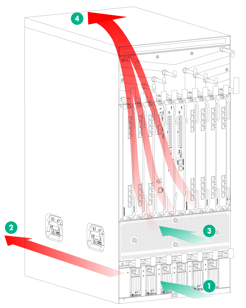
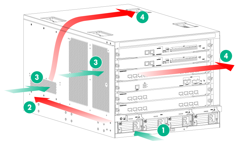
Figure 1 shows the airflow of the M9010, M9010-GM, or M9016-V chassis. Figure 2 shows the airflow of the M9006 and M9014 chassis.
Figure 1 Airflow of the M9010/M9010-GM/M9016-V chassis (M9010 as an example)
|
(1) Power supply air inlet |
(2) Power supply air outlet |
|
(3) Chassis air inlet |
(4) Chassis air outlet |
Figure 2 Airflow of the M9006/M9014 chassis (M9006)
|
(1) Power supply air inlet |
(2) Power supply air outlet |
|
(3) Chassis air inlet |
(4) Chassis air outlet |
Space
For easy installation and maintenance, follow these guidelines:
· The equipment room is at least 3 m (9.84 ft) high.
· Reserve a minimum of 1 m (3.28 ft) of clearance between the rack and walls or other devices.
· The dimensions of the rack are sufficient for the chassis. For more information about chassis specifications, see "Appendix B Chassis views and technical specifications."
Table 5 Device dimensions and rack requirements
|
Model |
Chassis dimensions |
Rack requirements |
|
M9006 |
· Height—353 mm (13.90 in)/8 RU · Width—440 mm (17.32 in) · Depth—757 mm (29.80 in) ¡ 660 mm (25.98 in) for the chassis ¡ 95 mm (3.74 in) for the cable management bracket at the front of the chassis ¡ 24 mm (0.94 in) for the switching fabric module ejector levers at the rear of the chassis |
· A minimum of 1.0 m (3.28 ft) in depth (recommended) · A minimum of 130 mm (5.12 in) between the front rack post and the front door · A minimum of 690 mm (27.17 in) between the front rack post and the rear door |
|
M9010/M9010-GM/M9016-V |
· Height—886 mm (34.88 in)/20 RU · Width—440 mm (17.32 in) · Depth—757 mm (29.80 in) ¡ 660 mm (25.98 in) for the chassis ¡ 95 mm (3.74 in) for the cable management bracket at the front of the chassis ¡ 24 mm (0.94 in) for the switching fabric module ejector levers at the rear of the chassis |
|
|
M9014 |
· Height—797 mm (31.38 in)/18 RU · Width—440 mm (17.32 in) · Depth—757 mm (29.80 in) ¡ 660 mm (25.98 in) for the chassis ¡ 95 mm (3.74 in) for the cable management bracket at the front of the chassis ¡ 24 mm (0.94 in) for the switching fabric module ejector levers at the rear of the chassis |
Installation tools
Table 6 lists the tools and equipment that you might use during installation, and all of them are user supplied. Prepare them before installation.
Table 6 Tools and equipment list
|
Category |
Tool |
|
Measuring and marking tools |
Long tape, ruler (of 1 meter, or 3.28 ft), gradienter, marker, chalk line, and pencil |
|
Drills |
Hammer drill, electric drill, and several auxiliary drill bits |
|
Fastening tools |
· Flat-blade screwdriver P4-75 mm · Phillips screwdriver P1-100 mm, P2-150 mm, and P3-250 mm · Socket wrench M5 · Socket wrench M6 |
|
Small tools |
Needle-nose pliers, diagonal pliers, combination pliers, wire-stripping pliers, crimping pliers, RJ-45 crimping pliers, file, and handsaw |
|
Auxiliary tools |
ESD wrist strap, hair brush, tweezers, paper knife, hand bellows, electric iron, solder wire, ladder, cable stripper, vacuum cleaner, crowbar, and rubber hammer |
|
Tools for fiber-optic cleaning |
Lint-free paper and optical fiber microscope |
|
Equipment |
Multimeter, 500 V Megohmmeter for measuring the insulation resistance, error detector, optical power meter, and earth resistance tester |
