- Table of Contents
-
- H3C SecPath M9000 Multi Service Security Gateway Series Installation Guides-6W106
- 00-Preface
- 01-Chapter 1 Chassis views
- 01-Chapter 1 Preparing for Installation
- 02-Chapter 2 Installing the Gateway
- 03-Chapter 3 Logging in to the Gateway and Configuring Basic Settings
- 04-Chapter 4 Troubleshooting
- 06-Chapter 6 Replacing FRUs
- 07-Appendix A FRUs and Compatibility Matrixes
- 08-Appendix B Technical Specifications
- 09-Appendix C LEDs
- 10-Appendix D Slot arrangement and interface numbering
- 11-Appendix E Cables
- 12-Appendix F Cabling Recommendations
- 13-Appendix G Repackaging the Gateway
- Related Documents
-
| Title | Size | Download |
|---|---|---|
| 09-Appendix C LEDs | 127.13 KB |
NSQM1FWEFGA0 firewall module LEDs
NSQ1FWCEA0 firewall module LEDs
NSQM1SSICASK1 security situation intelligent computer node module LEDs
Appendix C LEDs
The M9000 gateway series provides a lot of LEDs. You can determine the gateway operating status by examining the LEDs. For more information about the card LEDs, see the card manuals.
MPU LEDs
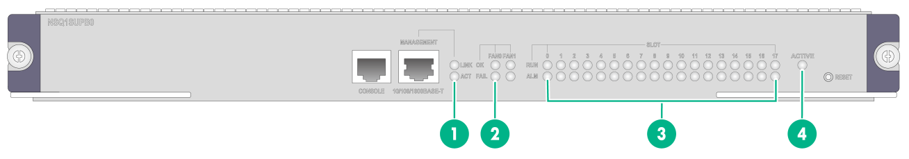
Figure 1 shows the LEDs on the MPU.
Figure 1 MPU LEDs (NSQ1SUPB0)
|
(1) Management Ethernet copper port LED |
(2) Fan LED |
|
(3) Card status LED |
(4) MPU active/standby status LED |
Management Ethernet copper port LEDs
Table 1 Management Ethernet copper port LED description
|
LINK |
ACT |
Description |
|
Steady on |
Flashing |
The port is receiving or sending data. |
|
Steady on |
Off |
A link is present. |
|
Off |
Off |
No link is present. |
Fan LEDs
Each MPU provides one OK LED and one FAIL LED for a fan tray.
· The M9006, M9010, M9010-GM, and M9016-V gateways each have one fan tray. The LEDs for the fan tray is FAN0.
· The M9014 gateway has two fan trays. The LEDs for the fan trays are FAN0 and FAN1.
Table 2 Fan LED description
|
OK |
FAIL |
Description |
|
Steady on |
Off |
The fan tray is operating correctly. |
|
Off |
Steady on |
The fan tray has failed or is not present. |
|
Off |
Off |
The gateway is not powered on. |
Card LEDs
Each MPU has the LEDs numbered the same as card slots to indicate the status of the active MPU, standby MPU, interface switch modules, interface modules, service modules, and switching fabric modules in the slots. Table 3 shows the LED description.
|
|
NOTE: Slot numbers are marked on top of the slots on the M9010, M9010-GM, and M9016-V gateways and on the right of the slots on the M9006 and M9014 gateways. |
|
RUN |
ALM |
Description |
|
Flashing |
Off |
The card is operating correctly. |
|
Flashing |
Steady on |
The card is loading software. If the LEDs keep in this state, the card software version is not compatible with the gateway software version. |
|
Flashing |
Flashing |
The card temperature exceeds the upper warning threshold or falls below the lower warning threshold. |
|
Steady on |
Steady on |
The card is in boot state or has failed. |
|
Steady on |
Off |
The MPU is in boot state. |
|
Off |
Off |
The card is not present. |
|
|
NOTE: It is normal that the ALM LED for an interface module lights for a period of time at the initial phase of the system startup. |
MPU active/standby status LED
Each MPU has one ACTIVE LED to indicate the active or standby status of the MPU.
Table 4 MPU ACTIVE LED description
|
LED status |
Description |
|
Steady on |
The MPU is active. |
|
Off |
· The MPU is in standby status. · The MPU has failed. Examine the card LED for an MPU problem. |
Service module LEDs
NSQM1FWEFGA0 firewall module LEDs
The NSQM1FWEFGA0 firewall module provides LEDs to indicate the operation status for the card and its interfaces.
Table 5 NSQM1FWEFGA0 LED description
|
LED |
LED mark |
Status |
Description |
|
Power on/standby button and system power LED |
|
Steady green |
The system has started up. |
|
Slow flashing green |
The system is starting up. |
||
|
Steady amber |
The system is in standby state. |
||
|
Off |
No power is present or the card is faulty. |
||
|
System status LED |
|
Steady green |
The system is operating correctly. |
|
Fast flashing green |
BMC is initializing. |
||
|
Alternating between yellow and green |
An alarm of low severity level has occurred. |
||
|
Slow flashing yellow |
An alarm of high severity level has occurred. |
||
|
RUN |
Slow flashing green |
The system has started up as configured and is operating correctly. |
|
|
Fast flashing green |
The system is loading software. |
||
|
Off |
No power is present or the card is faulty. |
||
|
Management Ethernet copper port LED |
|
Steady on |
A link is present on the port. |
|
Flashing |
The port is sending or receiving data. |
||
|
Off |
No link is present on the port. |
NSQ1FWCEA0 firewall module LEDs
The NSQ1FWCEA0 firewall module provides LEDs to indicate the operation status for the card and its interfaces.
Table 6 NSQ1FWCEA0 LED description
|
LED |
Status |
Description |
|
ALM |
Off |
The card is operating correctly and no alarm is generated. |
|
Steady red |
A critical alarm is generated for the card. To resolve the problem, view the system logs. |
|
|
RUN |
Off |
Power is not being supplied to the card or the card is faulty. |
|
Steady green |
The card is operating incorrectly. |
|
|
Slow flashing (1 Hz) |
The card has booted up and is operating correctly. |
|
|
Fast flashing (8 Hz) |
The card is loading software or has not started. |
|
|
LINK/ACT |
Off |
No link is present. |
|
Steady green |
A link is present. |
|
|
Flashing |
The port is sending or receiving data. |
NSQM1SSICASK1 security situation intelligent computer node module LEDs
The NSQM1SSICASK1 security situation intelligent computer node module provides LEDs to indicate the operation status for the card and the hard disk.
Table 7 NSQM1SSICASK1 LED description
|
LED |
Mark |
Status |
Description |
|
System power LED |
|
Steady green |
The system has started. |
|
Flashing green |
The system is starting. |
||
|
Steady amber |
The system is in standby state. |
||
|
Off |
No power input or the card is faulty. |
||
|
System run LED |
|
Steady green |
The system is operating correctly. |
|
Flashing green |
HDM is initializing. |
||
|
Flashing green and yellow |
A general alarm has occurred, including HDM alarms and hardware alarms. |
||
|
Flashing yellow |
A severe alarm has occurred, including HDM alarms, hardware alarms, and processor alarms. |
||
|
RUN |
Steady green |
The card is faulty. |
|
|
Flashing green (1 Hz) |
The card is operating correctly. |
||
|
Off |
The card is faulty or is not present. |
||
|
UID button LED |
UID |
Steady blue |
UID LED is activated. |
|
Flashing blue (1 Hz) |
The firmware is being upgraded or the system is being managed from HDM. |
||
|
Flashing blue (4 Hz) |
HDM is restarting. |
||
|
Off |
UID LED is not activated. |
LEDs of other service modules
Other service modules than the NSQM1FWEFGA0, NSQ1FWCEA0 and NSQM1SSICASK1 provide LEDs to indicate the operation status for the card and the hard disk.
Table 8 LED description for other service modules except the NSQM1FWEFGA0/NSQ1FWCEA0/NSQM1SSICASK1
|
LED |
Status |
Description |
|
Hard disk LED (HD) |
Off |
The hard disk has failed or is not present. |
|
Flashing green |
The hard disk is reading and writing data. |
|
|
Steady green |
The hard disk is operating correctly. |
|
|
System status LED (SYS) |
Off |
No power is being input or the card is faulty. |
|
Slow flashing |
The system has started up and is operating correctly. |
|
|
Fast flashing |
The system is loading software. |
|
|
NOTE: · The hard disk slots on the NSQM1ADEDFGA0, NSQM1AFC2000GDFGA0, NSQM1FWDFG0, and NSQM1GMDSCA1 modules cannot be used. · For more information about service module LEDs, see the card manuals that come with the service modules. |
Interface module LEDs
GE copper port LED
Table 9 GE copper port LED description
|
LED status |
Description |
|
Flashing yellow |
The port is receiving or sending data at 10/100 Mbps. |
|
Flashing green |
The port is receiving or sending data at 1000 Mbps. |
|
Steady yellow |
A 10/100 Mbps link is present. |
|
Steady green |
A 1000 Mbps link is present. |
|
Off |
No link is present. |
GE fiber port LED
The interface modules that have GE fiber ports provide GE fiber port LEDs to indicate the link status and data receiving/forwarding status of the GE fiber ports.
Table 10 GE fiber port LED description
|
LED status |
Description |
|
Flashing |
The port is receiving or sending data. |
|
On |
A link is present. |
|
Off |
No link is present. |
10G fiber port LED
The interface modules that have 10G fiber ports provide 10G fiber port LEDs to indicate the link status and data receiving/forwarding status of the 10G fiber ports. The 10G fiber port LED type depends on the transceiver module type supported by the port.
Table 11 SFP+ fiber port LED description
|
LED status |
Description |
|
Flashing yellow |
The port is receiving or sending data at 1000 Mbps. |
|
Flashing green |
The port is receiving or sending data at 10 Gbps. |
|
Steady yellow |
A 1000 Mbps link is present. |
|
Steady green |
A 10 Gbps link is present. |
|
Off |
No link is present. |
Table 12 XFP fiber port LED description
|
LINK |
ACT |
Description |
|
On |
Flashing |
A link is present, and the port is receiving or sending data. |
|
On |
Off |
A link is present, but no data is being received or sent. |
|
Off |
Off |
No link is present. |
40G fiber port LEDs
The interface modules that have 40G fiber ports provide 40G fiber port LEDs to indicate the link status and data receiving/forwarding status of the 40G fiber ports.
Table 13 40G fiber port LED description
|
LED status |
Description |
|
Flashing |
The port is receiving or sending data. |
|
On |
A link is present. |
|
Off |
No link is present. |
100G fiber port LEDs
The interface modules that have 100G fiber ports provide 100G fiber port LEDs to indicate the link status and data receiving/forwarding status of the 100G fiber ports.
Table 14 100G fiber port LED description
|
LED status |
Description |
|
Flashing |
The port is receiving or sending data. |
|
On |
A link is present. |
|
Off |
No link is present. |
Switching fabric module LEDs
The switching fabric module has one RUN LED and one ALM LED to indicate its operating status.
Table 15 Switching fabric module LED description
|
RUN LED |
ALM LED |
Description |
|
Flashing |
Off |
The switching fabric module is operating correctly. |
|
Off |
On |
The switching fabric module is faulty. |
|
Flashing |
On |
The temperature of the switching fabric module has exceeded the upper or lower limit. |
|
Off |
Off |
The switching fabric module has not started. |
|
On |
Off |
The switching fabric module is in boot state. |
Fan tray status LEDs
Each fan tray has one OK LED and one FAIL LED to indicate its operating status.
Table 16 Fan tray LED description
|
OK |
FAIL |
Description |
|
On |
Off |
The fan tray is operating correctly. |
|
Off |
On |
The fan tray is faulty. |
|
Off |
Off |
The fan tray is not powered on. |
Power supply LEDs
The NSQM1AC2500 power supply has one AC LED and one DC LED to indicate its operating status. The NSQM1DC2400 power supply has one INP OK LED and one DC/FLT LED to indicate its operating status.
Table 17 NSQM1AC2500 power NSQM1AC2500 LED description
|
LED |
Status |
Description |
|
AC |
Off |
· The power supply has no power input. · The input voltage is too low, and the power supply is in self protection state. |
|
Green |
The power input is normal. |
|
|
DC |
Green |
The power supply is outputting power normally. |
|
Red |
The power supply is experiencing an output problem, including output short-circuit, output overcurrent, output overvoltage, input undervoltage, or remote poweroff, and has entered the self protection state. |
|
|
Orange |
The power supply is in an overtemperature condition and has entered the self protection state. |
Table 18 NSQM1DC2400 power supply LED description
|
LED |
Status |
Description |
|
INP OK |
Off |
· The power supply has no power input. · The input voltage is too low, and the power supply is in self protection state. |
|
Green |
The power input is normal. |
|
|
DC/FLT |
Green |
The power supply is outputting power normally. |
|
Red |
The power supply is experiencing an output problem, including output short-circuit, output overcurrent, output overvoltage, input undervoltage, or remote poweroff, and has entered the self protection state. |
|
|
Orange |
The power supply is in an overtemperature condition and has entered the self protection state. |
