- Table of Contents
-
- H3C SecPath M9000 Multi Service Security Gateway Series Installation Guides-6W106
- 00-Preface
- 01-Chapter 1 Chassis views
- 01-Chapter 1 Preparing for Installation
- 02-Chapter 2 Installing the Gateway
- 03-Chapter 3 Logging in to the Gateway and Configuring Basic Settings
- 04-Chapter 4 Troubleshooting
- 06-Chapter 6 Replacing FRUs
- 07-Appendix A FRUs and Compatibility Matrixes
- 08-Appendix B Technical Specifications
- 09-Appendix C LEDs
- 10-Appendix D Slot arrangement and interface numbering
- 11-Appendix E Cables
- 12-Appendix F Cabling Recommendations
- 13-Appendix G Repackaging the Gateway
- Related Documents
-
| Title | Size | Download |
|---|---|---|
| 06-Chapter 6 Replacing FRUs | 827.57 KB |
Contents
Replacing an interface subcard
Replacing a transceiver module
Replacing an XFP/SFP+/SFP/QSFP+/QSFP28 module
Replacing FRUs
|
|
CAUTION: · When replacing FRUs while the gateway is running, be aware of electrical safety hazards. · Strictly follow the replacement procedures provided in this chapter to avoid device damage or bodily injury. · Wear an ESD wrist strap during the replacement and make sure the wrist strap has a good skin contact and is correctly grounded. For more information, see "Attaching an ESD wrist strap." |
The gateway uses a modular, hot-swappable architecture, and supports field replaceable units (FRUs). You can replace any of FRUs when the gateway is running.
Replacing a power supply
|
|
WARNING! · Do not install AC and DC power supplies on the same M9000 gateway. · Power supplies on an M9000 gateway must be the same model. When the new power supplies and the power supplies operating on the gateway are not the same model, power off the gateway and remove all power supplies on the gateway before replacement. · Provide a circuit breaker to the power line for each power supply. Before replacing a power supply, turn off its circuit breaker. · The power supply may be of high temperature. Remove it with caution. · To install the removed power supply to the chassis again, install it after the status LED on it is off. |
Figure 1 Power supply removal flow
![]()
Figure 2 Power supply installation flow
![]()
The replacement procedures for the AC, DC, and HVDC power supplies are the same. To replace a power supply:
1. Prepare an antistatic mat to place the removed power supply.
2. Turn off the circuit breaker.
3. Remove the power cord plug from the power supply.
¡ AC power cord—Remove the cable ties from the power cord, and then remove the power cord plug from the power supply.
¡ DC power cord—Remove the cable ties from the power cord, loosen the fastening screw on the power cord, and then remove the power cord plug from the power supply.
¡ HVDC power cord—Remove the cable ties from the power cord, and then remove the power cord plug from the power supply.
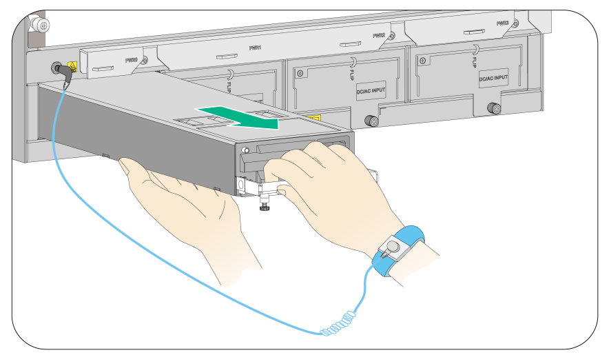
4. Use a Phillips screwdriver to loosen the captive screw on the power supply, and then grasp the captive screw between your thumb and index finger to carefully pull out the handle on the power supply.
5. Holding the power supply handle with one hand and supporting the bottom of the power supply with the other, gently pull the power supply out.
6. Put the removed power supply on the antistatic mat.
7. Install a new power supply. For the installation procedure, see "Installing a power supply."
If no new power supply is to be installed, install a filler panel to ensure adequate ventilation and dust prevention.
Figure 3 Removing the vertically-oriented AC power supply (M9010, M9010-GM, M9014, and M9016-V)
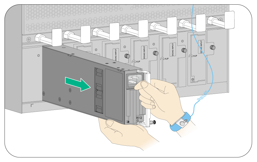
Figure 4 Removing the horizontally-oriented AC power supply (M9006)
Replacing a card
The MPUs, interface switch modules, interface modules, and service modules are hot swappable.
The cards on the M9000 gateways can be installed in horizontal or vertical slots, and the replacement procedures are the same. The following takes a card installed in a horizontal slot as an example.
To replace a card:
1. Prepare an antistatic mat to place the removed card.
2. If the card is an MPU, interface module, or service module, remove all its cables.
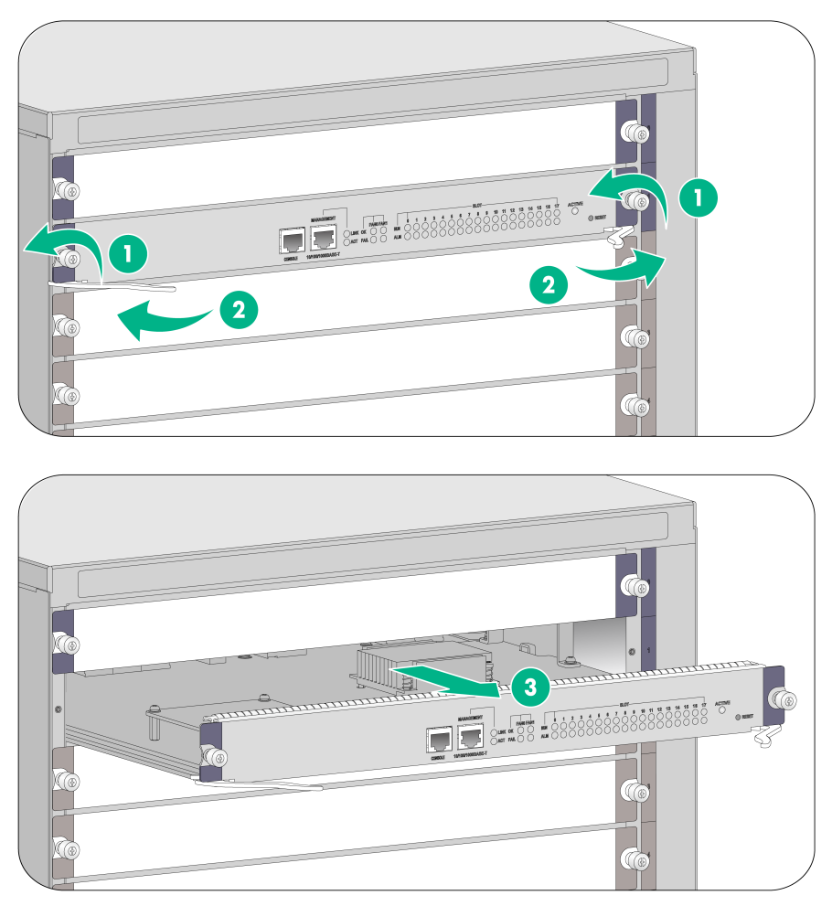
3. Use a Phillips screwdriver to remove the captive screw on the card, as shown by callout 1 in Figure 5.
4. Move the ejector levers outwards to separate the card from the backplane, as shown by callout 2 in Figure 5.
5. Use one hand to slowly move the card outwards. Supporting the bottom of the card with the other hand, pull the card out of the slot along slide rails, as shown by callout 3 in Figure 5.
6. Put the removed card on the antistatic mat.
7. Install a new card. For the installation procedures, see "Installing a card."
If no new card is to be installed, install a filler panel to ensure adequate ventilation and dust prevention.
|
(1) Loosen the captive screw |
(2) Move the ejector levers outwards |
|
(3) Take out the card |
|
Replacing an interface subcard
|
|
IMPORTANT: Do not hot swap the interface subcards. |
To replace an interface subcard:
1. Remove the interface switch module where the interface subcard resides. For the removal procedure, see "Replacing a card."
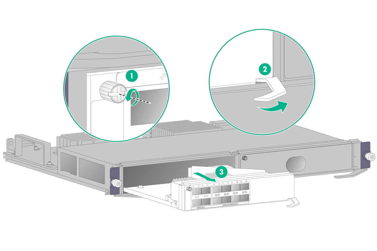
2. Use a Phillips screwdriver to loosen the captive screw on the left of the subcard.
3. Open the ejector lever on the subcard, and then pull the subcard part way out of the slot along the guide rails. Supporting the subcard bottom with one hand, gently pull the subcard out of the slot with the other.
4. Place the removed subcard on the antistatic mat.
5. Install a new interface subcard. For the installation procedure, see "Installing an interface subcard."
Figure 6 Removing an interface subcard
Replacing a fan tray
|
|
CAUTION: To avoid bodily injury, do not touch the rotating fans when replacing the fan tray. |
When the fan tray fails, replace the fan tray to ensure normal operation of the gateway.
The fan tray removal and installation procedures for all M9000 gateways are the same, even though the fan tray slot is vertically oriented for the M9006 and M9014 gateways and horizontally oriented for the M9010, M9010-GM, and M9016-V gateways. This section takes removing and installing a vertically oriented fan tray on an M9006 as an example.
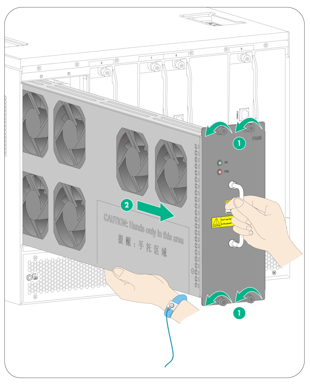
Removing a fan tray
|
|
CAUTION: To ensure normal ventilation, install a new fan tray within two minutes after removing the old one. |
To remove a fan tray:
1. Prepare an antistatic mat to place the fan tray to be removed.
2. Loosen the captive screws on the fan tray, as shown by callout 1 in Figure 7.
3. Hold the handle of the fan tray with one hand to gently pull the fan tray part way out of the chassis. After the fans stop rotating, support the bottom of the fan tray with the other hand, and take out the fan tray from the chassis, as shown by callout 2 in Figure 7.
4. Put the removed fan tray on the antistatic mat.
|
(1) Loosen the captive screws on the fan tray |
(2) Take the fan tray out of the chassis |
Installing a fan tray
1. Unpack the fan tray.
2. Holding the handle of the fan tray with one hand and supporting bottom with the other, gently slide the fan tray along the guide rails into the slot until it is firmly secured in the slot.
3. Fasten the captive screws on the fan tray.
Replacing an air filter
|
|
CAUTION: · Clean air filters every three months to guarantee adequate ventilation and avoid over-temperature. · Ensure electricity safety when replacing air filters on an operating gateway. |
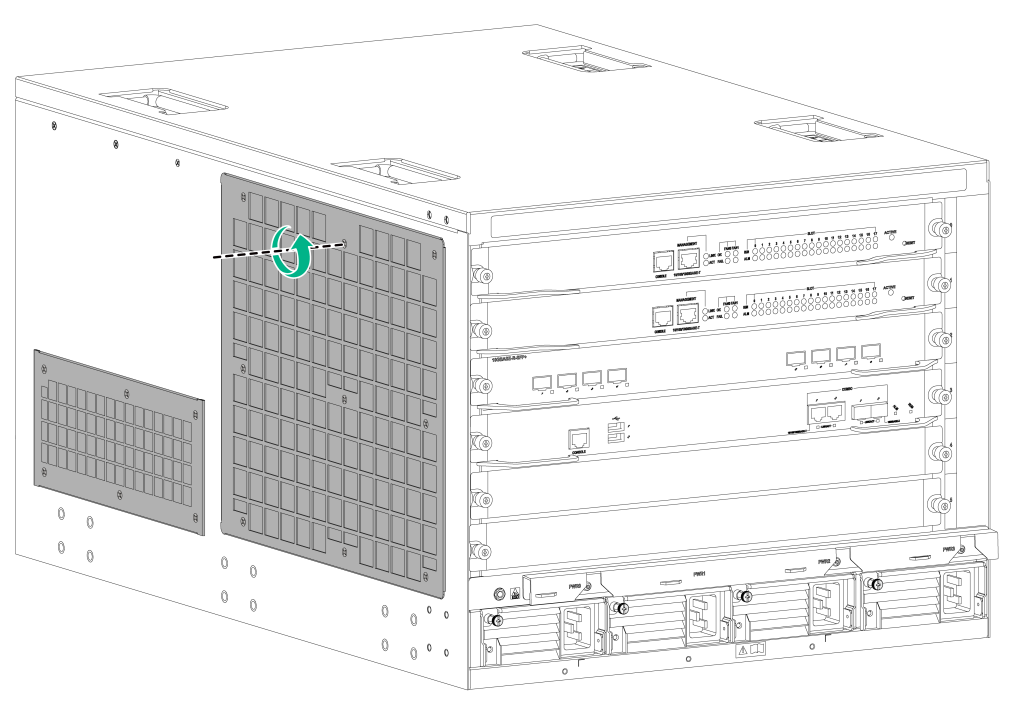
The air filter removal and installation procedures for all M9000 gateways are the same. This section takes removing and installing an air filter on an M9006 as an example.
1. Loosen the screws on the air filter, as shown by callout 1 in Figure 8.
2. Remove the air filter from the chassis.
3. Install the cleaned air filter to the gateway.
For the installation procedures, see "(Optional) Installing air filters."
Figure 8 Removing an air filter (M9006)
|
|
TIP: Keep secure the removed screws from the air filters of the M9006 and M9014 gateways. |
Replacing a transceiver module
|
|
WARNING! When you install or remove a transceiver module: · Do not stare at the fibers to avoid hurting your eyes. · Do not touch the golden plating on the module. |
Make sure the optical transceiver modules at the two ends of an optical fiber are the same model. In case of limited space, you can use the supplied tweezers to install or remove a transceiver module as a best practice.
Replacing an XFP/SFP+/SFP/QSFP+/QSFP28 module
1. Remove the optical connectors on the module.
2. Pivot the clasp down to the horizontal position.
For a QSFP+ or QSFP28 module that uses a plastic pull latch, skip this step.
3. Grasp the clasp on the module and carefully pull the module out of the slot.
4. Put the filler plug on the removed module, and put the remove module into its original shipping materials.
5. Install a new module.
For the installation procedures, see "Installing an XFP/SFP+/SFP/QSFP+/QSFP28 transceiver module."
Replacing a CFP module
1. Wear an ESD wrist strap and make sure it makes good skin contact and is correctly grounded.
For more information, see "Attaching an ESD wrist strap."
2. Remove the optical fiber from the module.
3. Loosen the captive screws on the module.
4. Carefully pull the module out of the slot.
5. Insert the dust plug into the removed module, and put the removed module into its original package (recommended) or an antistatic bag.
6. Install a new CFP module.
For the installation procedures, see "Installing a CFP module."
