- Table of Contents
-
- H3C S10500X-G Switch Series Installation Guide-6W100
- 00-Preface
- 01-Installation Precautions
- 02-Preparing for Installation
- 03-Installing the Switch
- 04-Installing FRUs
- 05-Connecting Your Switch to the Network
- 06-Troubleshooting
- 07-Replacement Procedures
- 08-Appendix A Engineering Labels
- 09-Appendix B Cabling Recommendations
- 10-Appendix C Repackaging the Switch
- Related Documents
-
| Title | Size | Download |
|---|---|---|
| 04-Installing FRUs | 6.11 MB |
Installing cable management brackets
Installing switch fabric modules
Installing AC/DC power supplies
Connecting the power cord for a PSR1600B-12A-B power supply
Connecting the power cord for a PSR2000-12D-B power supply
Connecting the power cord for a PSR1600-54A-B power supply
Installing transceiver modules and optical fibers
Installing an SFP/SFP+/SFP28/QSFP+/QSFP28/QSFP-DD transceiver module
4 Installing FRUs
As a best practice, connect power cords after installing all required FRUs. To ensure good ventilation, install filler panels in unused slots.
Long-time exposure to strong air flow might cause discomfort. To avoid this hazard, do not stand close to the air outlet vents while the switch is operating. If you must be next to the switch on the air outlet vent side for an extended period, avoid the air flow or take other protective measures.
|
|
TIP: Keep the chassis and the component packages for future use. |
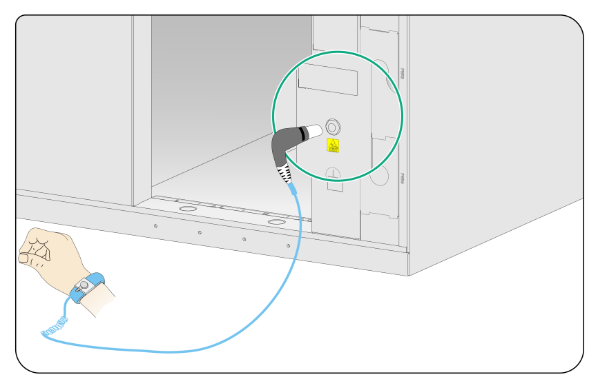
Attaching an ESD wrist strap
The switch is provided with an ESD wrist strap. To minimize ESD damage to electronic components, wear the ESD wrist strap and make sure it is reliably grounded before you install FRUs.
To attach an ESD wrist strap:
1. Make sure the switch is reliably grounded. For information about how to ground your switch, see "Grounding the switch."
2. Put on the wrist strap.
3. Tighten the wrist strap to make sure it makes good skin contact.
Make sure the resistance reading between your body and the ground is between 1 and 10 megohms.
4. As shown in Figure4-1, insert the ESD wrist strap into the ESD jack on the chassis.
Figure4-1 Attaching an ESD wrist strap (S10506X-G)
Installing modules
|
|
IMPORTANT: Before installing a module in the chassis, make sure the connectors on the module are not broken or blocked. |
Unless otherwise stated, MPUs, service modules, and switch fabric modules are collectively referred to as "modules" in this document. The modules are hot swappable.
For the modules available for the switch, see "FRUs and compatibility matrixes" in H3C S10500X-G Switch Series Hardware Information and Specifications.
Installing MPUs
|
|
CAUTION: · If you are not to install an MPU in an MPU slot, keep the filler panel in the slot to prevent dust and ensure good ventilation in the switch. · When you install an MPU, avoid damaging the connectors on the MPU. · To prevent a filler panel from being drawn into the chassis when fan speed is high, use both hands to grasp the filler panel by its two sides during filler panel installation and removal on an operating switch. |
|
|
IMPORTANT: Captive screws are required to install an MPU or service module on the switch. As a best practice, use a torque of 5.5 kgf-cm (0.54 Nm) to fasten the captive screws. |
You can install one MPU, or two MPUs for redundancy on the switch. If you are to install one MPU, install it in either of the MPU slots.
The installation procedure is similar for MPUs and service modules. For how to install an MPU or service module, see "Installing service modules."
Installing service modules
|
|
CAUTION: · To prevent a filler panel from being drawn into the chassis when fan speed is high, use both hands to grasp the filler panel by its two sides during filler panel installation and removal on an operating switch. · Keep filler panels installed on unused service module slots. |
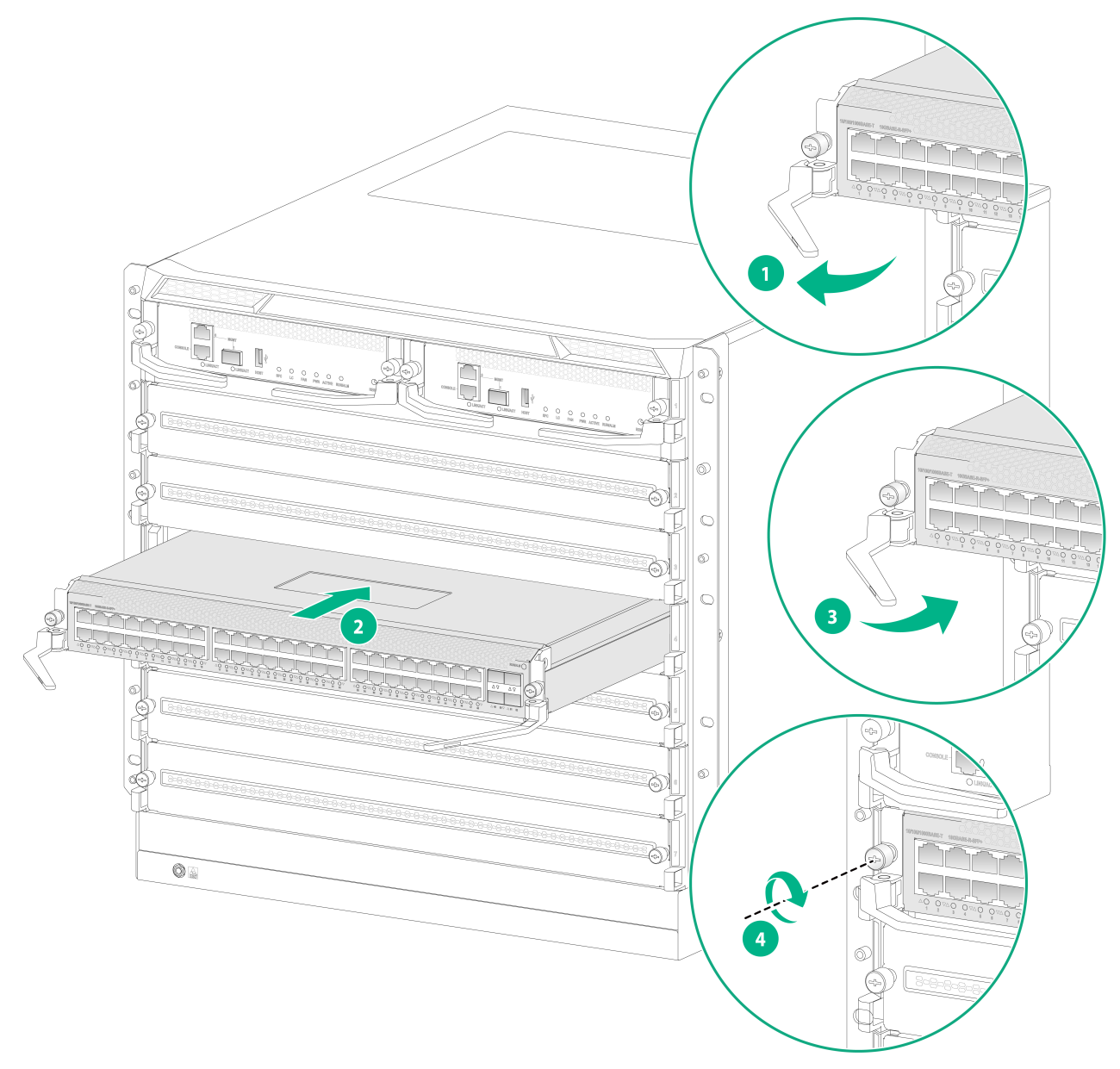
To install a service module:
1. As shown by callout 1 in Figure4-2, open the ejector levers on the service module.
2. As shown by callout 2 in Figure4-2, orient the service module with the lettering on it upward. Holding the module by the front panel with one hand and supporting its bottom with the other, insert the service module steadily into the target slot along the guide rails.
Keep the service module parallel to the slot to avoid touching other components in the chassis.
3. Push the service module until the brakes on the ejector levers engage the edges of the slot.
4. Continue to push the service module by its middle part on the front panel until you cannot push it.
5. As shown by callout 3 in Figure4-2, close the ejector levers until they come in close contact with the front panel of the service module.
6. As shown by callout 4 in Figure4-2, use a screwdriver to fasten the captive screws on the service module.
Figure4-2 Installing a service module (S10506X-G)
Installing a service module filler panel
|
|
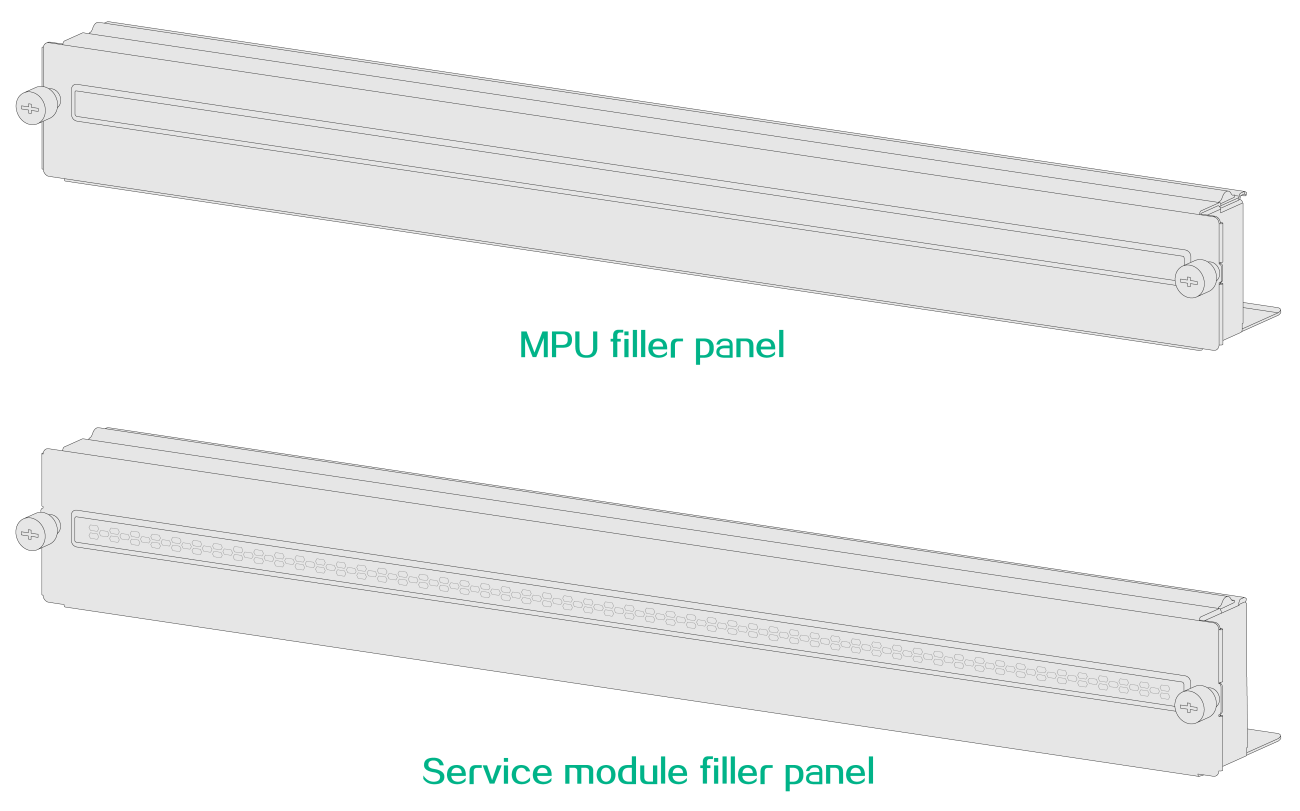
CAUTION: Before installing a filler panel, differentiate between an MPU filler panel and a service module filler panel. A service module filler panel has air outlet vents on its front panel, but an MPU filler panel does not. |
Figure4-3 An MPU filler panel and a service module filler panel (S10512X-G)
To install a service module filler panel:
1. Align the installation holes in the service module filler panel with the holes in the target slot.
2. Fasten the two captive screws on the service module filler panel.
Figure4-4 Installing a service module filler panel (S10512X-G)
Removing a service module filler panel
To install a service module, remove the filler panel from the target slot.
To remove a service module filler panel:
1. Loosen the captive screws on the service module filler panel.
2. Remove the service module filler panel.
Figure4-5 Removing a service module filler panel (S10512X-G)
|
|
NOTE: · Keep the removed filler panel secure for future use. · As a best practice, use a torque of 5.5 kgf-cm (0.54 Nm) to fasten the captive screws. |
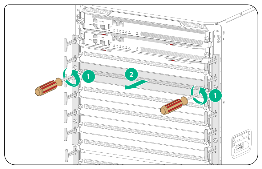
Installing cable management brackets
The cable management brackets are installed on the two sides of the service module slots. As a best practice, install cable management brackets after you have installed service modules.
Installing a pair of cable management brackets
This section uses the S10506X-G switch as an example.
To install a pair of cable management brackets:
1. Align the installation holes in the cable management bracket with the mounting holes in the mounting bracket.
2. Use two screws to secure the cable management bracket to the mounting bracket.
3. Repeat the procedure to install the other cable management bracket.
Figure4-6 Installing cable management brackets (S10506X-G)

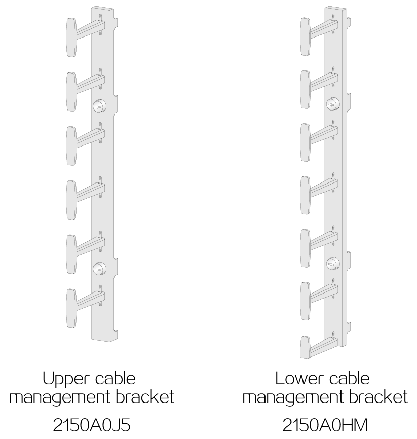
Installing two pairs of cable management brackets
This section uses the S10512X-G switch as an example.
Figure4-7 shows the upper and lower cable management brackets for the S10512X-G switch. The upper cable management bracket with a product code of 2150A0J5 is shorter than the lower cable management bracket with a product code of 2150A0HM.
Figure4-7 Upper and lower cable management brackets
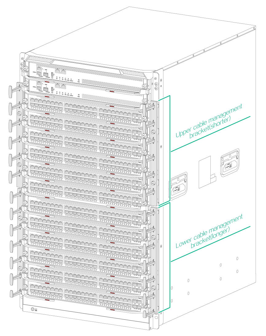
To install two pairs of cable management brackets:
1. Align the installation holes in the upper cable management bracket with the mounting holes in the upper part of the mounting bracket. Use two screws to secure the upper cable management bracket to the mounting bracket.
2. Align the installation holes in the lower cable management bracket with the mounting holes in the lower part of the mounting bracket. Use two screws to secure the lower cable management bracket to the mounting bracket.
3. Repeat the procedure to install the other pair of cable management brackets.
Figure4-8 Installing cable management brackets (S10512X-G)
Installing switch fabric modules
|
|
CAUTION: · When you install a switch fabric module, avoid damaging the connectors on it. · Each switch fabric module for an S10508X-G or S10512X-G switch has a protection box at the connectors side. Before you install a switch fabric module, first remove the metal protection box. · Install switch fabric modules or switch fabric module slot filler panels before you install the fan tray. · Install filler panels in the empty switch fabric module slots to prevent dust and ensure good ventilation in the switch. · To replace or install a switch fabric module for an operating switch, first remove the fan tray that covers the slot of the switch fabric module. Install the fan tray immediately after the replacement or installation. After the fan tray starts operating, you can replace or install switch fabric modules whose slots are covered by the other fan tray. · The smart speed adjustment feature increases the fan speed when only one fan tray is operating. Take noise protection measures such as wearing an earmuff or earplug. In addition, make good preparation before hot swapping a switch fabric module to minimize the operation time. · Install a minimum of two switch fabric modules on the switch according to the switch fabric module slot priority description at the chassis rear strictly. |
An S10506X-G switch has four vertically-oriented switch fabric module slots at the chassis rear.
An S10508X-G and an S10512X-G switch each have six vertically-oriented switch fabric module slots at the chassis rear.
To install a switch fabric module:
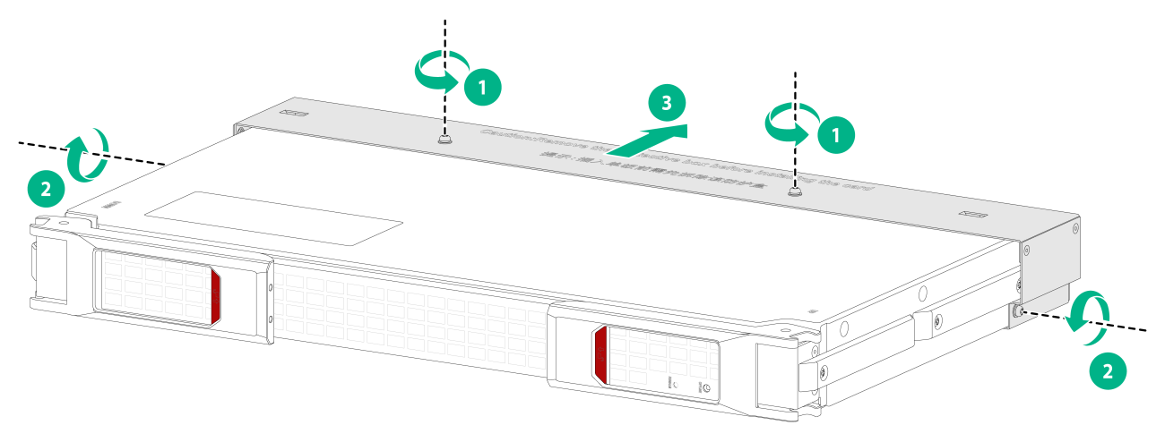
1. Place the switch fabric module on the workbench horizontally, and then remove the protection box (if any) at the connectors side as shown in Figure4-9.
Figure4-9 Removing the protection box from the switch fabric module (S10508X-G)
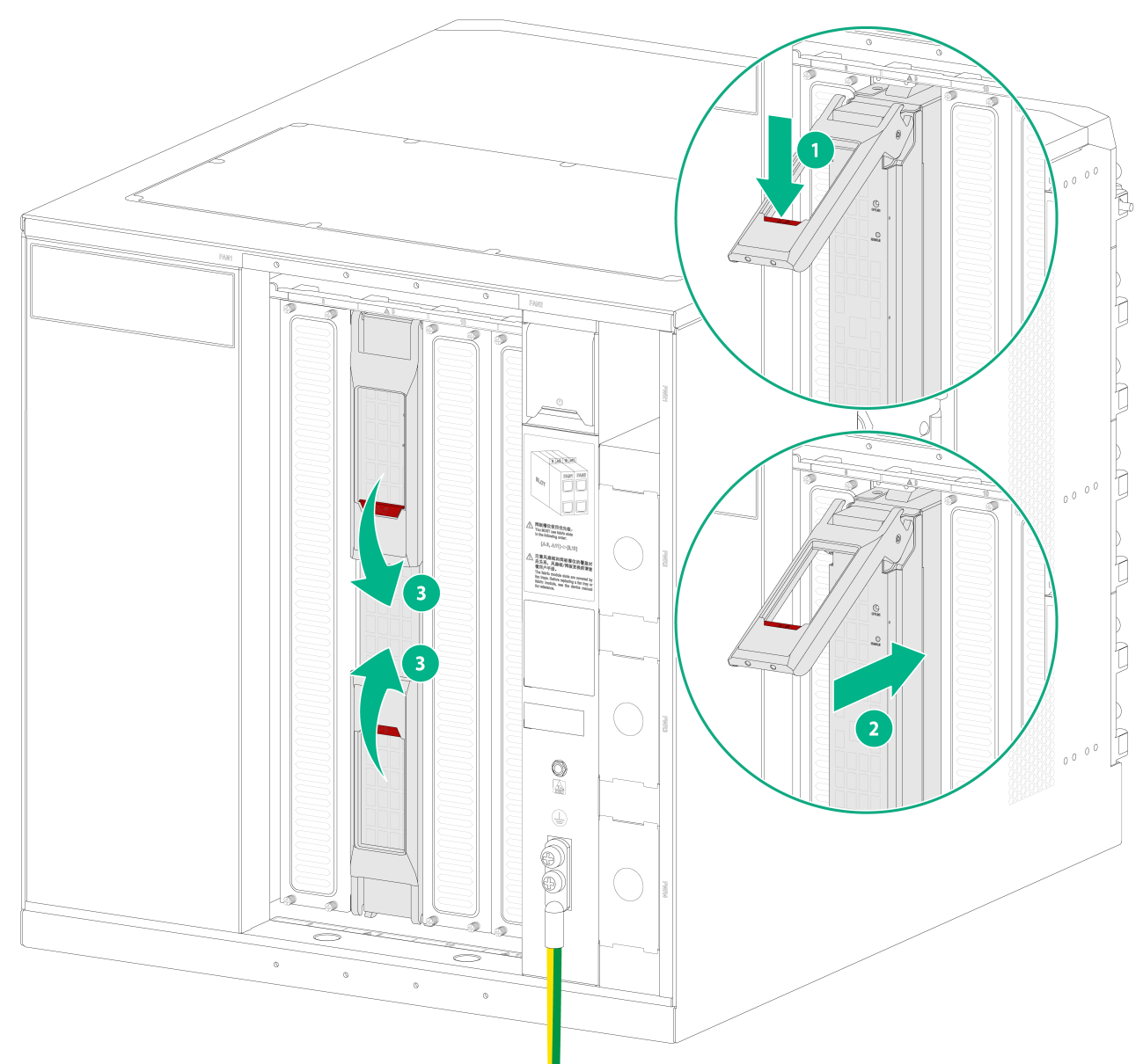
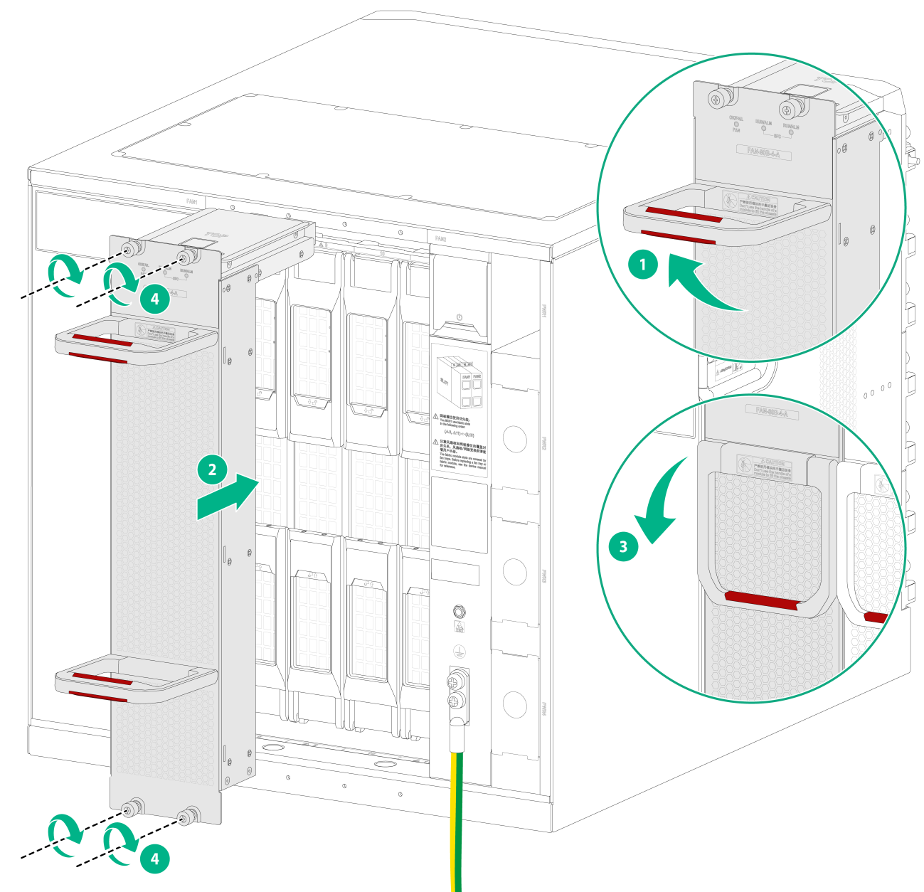
2. As shown by callout 1 in Figure4-10, release the ejector levers by pressing the spring clips for the ejector levers.
3. Correctly orient the switch fabric module. .Align the switch fabric module with the target slot. Fully open the ejector levers with both hands and push the switch fabric module into the slot slowly until you cannot push it. See callout 2 in Figure4-10.
Keep the module parallel to the slot to avoid touching other components in the chassis.
4. As shown by callout 3 in Figure4-10, simultaneously rotate the ejector levers inward until the spring clips lock the ejector levers in place and the switch fabric module is completely seated in the slot.
Figure4-10 Installing a switch fabric module (S10506X-G)
Installing a filler panel in a switch fabric module slot
|
|
IMPORTANT: Captive screws are required to install a filler panel in a switch fabric module slot. As a best practice, use a torque of 5.5 kgf-cm (0.54 Nm) to fasten the captive screws. |
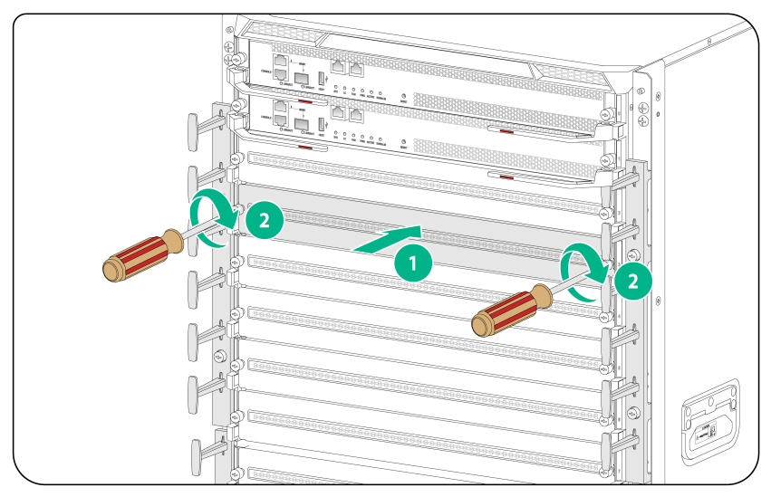
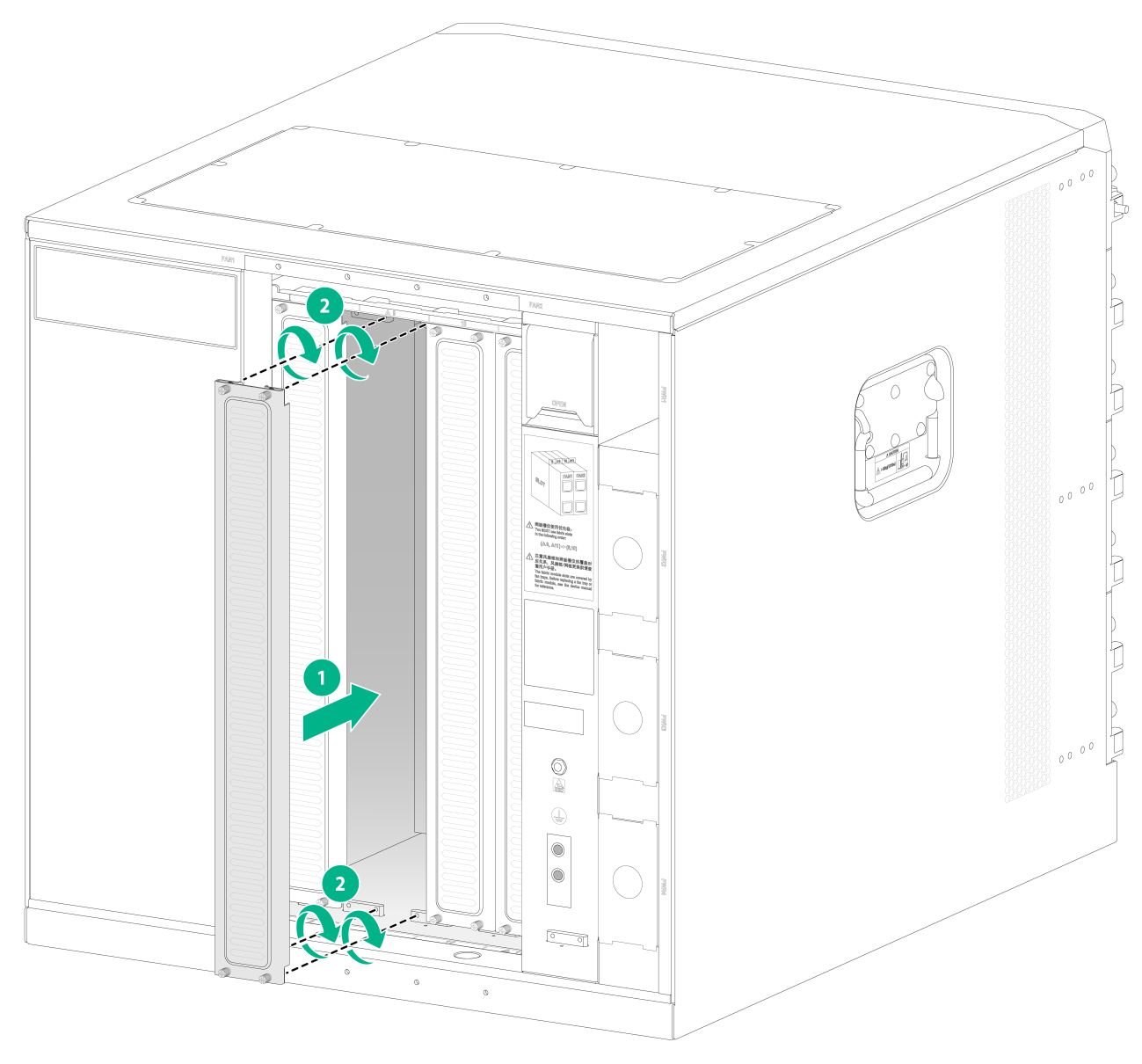
To install a filler panel in a switch fabric module slot:
1. Align the installation holes in the filler panel with the holes in the slot edges.
2. Insert the filler panel into the target switch fabric module slot.
3. Fasten the four captive screws on the filler panel.
Figure4-11 Installing a filler panel in a switch fabric module slot (S10506X-G)
Removing a filler panel from a switch fabric module slot
To install a switch fabric module, remove the filler panel from the target slot.
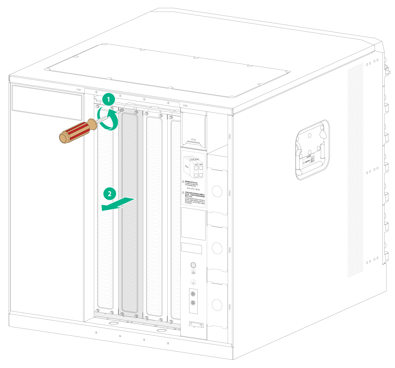
To remove a filler panel:
1. Loosen the captive screws on the filler panel.
2. Pull the filler panel out of the slot.
Keep the removed the filler panel secure for future use.
Figure4-12 Removing a filler panel from a switch fabric module slot (S10506X-G)
Installing fan trays
|
|
WARNING! · When removing the fan tray, keep your hands and fingers away from the spinning fan blades. Let the fan blades completely stop before you remove the fan tray. · The fan tray is high and heavy. To avoid switch damage and bodily injury, use two people to install or remove a fan tray. |
|
|
CAUTION: · To avoid fan tray damage, use both hands when installing or removing a fan tray. · To prevent dust from entering the chassis, make sure each fan tray slot has a fan tray installed when the switch is not in use. |
|
|
CAUTION: Fan trays are hot swappable. When you hot swap fan trays, follow these guidelines: · Ensure electricity safety. · You can hot swap a fan tray only when the other fan tray is operating correctly. · When you hot swap a fan tray, the fan speed of the remaining fan trays automatically increases. Take noise protection measures such as wearing an earmuff or earplug. In addition, make preparations before hot swapping a fan tray to minimize the operation time. |
|
|
IMPORTANT: A fan tray covers switch fabric module slots. Install the switch fabric modules or filler panels in the switch fabric module slots before installing a fan tray. · If a switch fabric module is installed in a switch fabric module slot, make sure the spring clips lock the ejector levers of the switch fabric module in place. · If a switch fabric module filler panel is installed in a switch fabric module slot, make sure the switch fabric module filler panel is secured in place by captive screws. |
To install a fan tray:
1. Orient the fan tray with the side marked "TOP" facing upwards, and then pivot up the fan tray handles to make them perpendicular to the fan tray.
2. Holding the fan tray handles, insert the fan tray into the slot along the guide rails. Keep the fan tray as straight as possible. Pivot down the fan tray handles until they are flush against the fan tray faceplate.
3. Fasten the captive screws on the fan tray.
As a best practice, use a torque of 5.5 kgf-cm (0.54 Nm) to fasten the captive screws.
Figure4-13 Installing a fan tray (S10506X-G)
Installing power supplies
Installing AC/DC power supplies
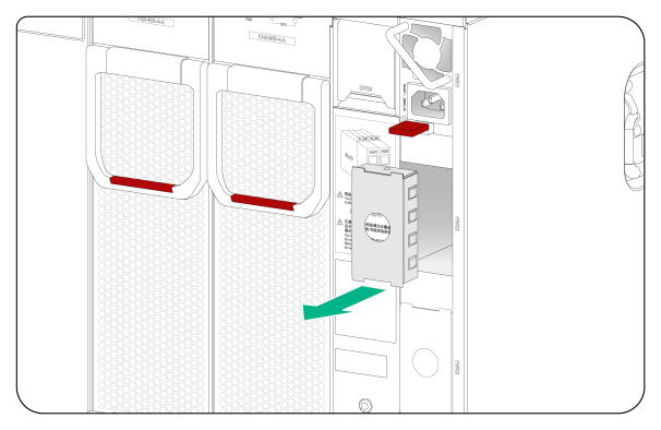
1. If a filler panel is installed in the slot, remove the filler panel first.
2. As shown in Figure4-14, use your forefinger to hold the filler panel through the hole and pull out the filler panel.
Figure4-14 Removing a filler panel (S10506X-G)
3. Correctly orient the power supply. Holding the power supply handle with one hand and supporting the bottom of the power supply with the other, slide the power supply along the guide rails into the slot until you hear a click.
Figure4-15 Installing a power supply (S10506X-G)

Installing PoE power supplies
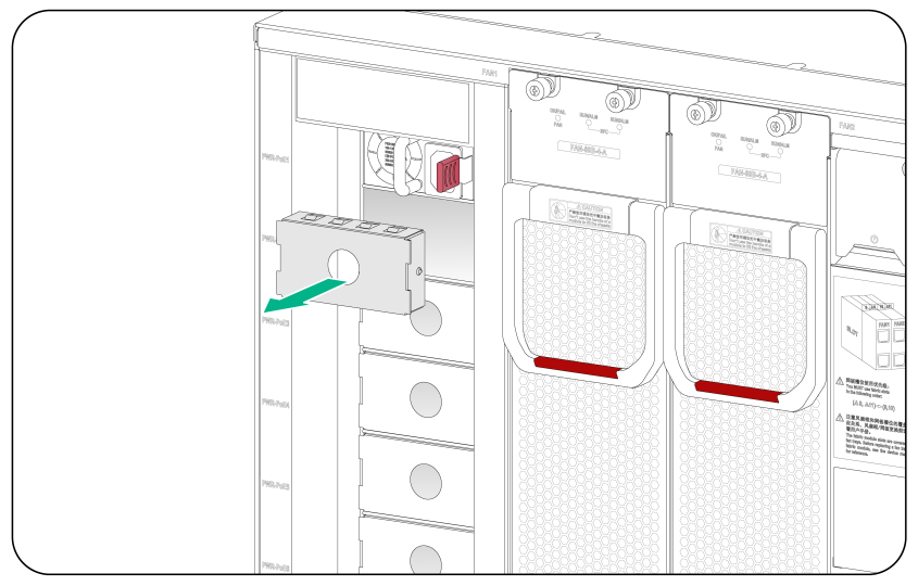
1. If a filler panel is installed in the PoE power supply slot, remove the filler panel first.
2. As shown in Figure4-16, use your forefinger to hold the filler panel through the hole and pull out the filler panel.
Figure4-16 Removing a filler panel (S10506X-G-PoE)
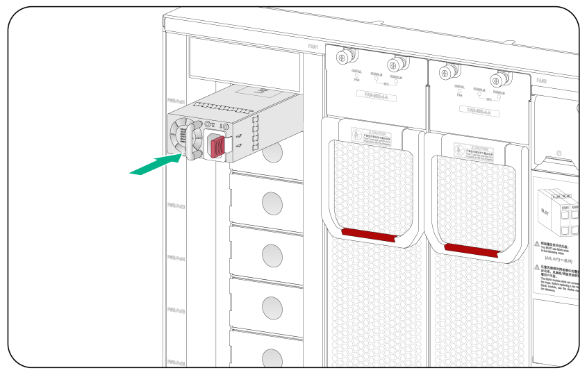
3. Correctly orient the PoE power supply. Holding the power supply handle with one hand and supporting the bottom of the power supply with the other, slide the power supply along the guide rails into the slot until you hear a click.
Figure4-17 Installing a PoE power supply (S10506X-G-PoE)
Connecting the power cord
|
|
CAUTION: · Power on the switch after you have installed fan trays on the switch. · Make sure each power cord has a separate circuit breaker. · Turn off the circuit breaker before you connect the power cord. |
Connecting the power cord for a PSR1600B-12A-B power supply
1. Connect the AC power cord connector to the AC input receptacle of the power supply.
2. Use a releasable cable tie or self-adhesive cable tie (provided with the power supply) to secure the power cord to the handle of the power supply.
3. Connect the other end of the power cord to an external AC power source.
Figure4-18 Connecting the power cord for a PSR1600B-12A-B power supply (S10506X-G)
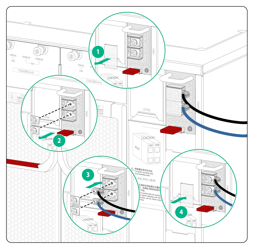
Connecting the power cord for a PSR2000-12D-B power supply
1. As shown by callout 1, remove the protection cover from the power supply.
2. As shown by callout 2, use a Phillips screwdriver to loosen the screws on the wiring terminals.
3. As shown by callout 3, connect the end of the DC power cord marked with – to the negative terminal (–) on the power supply and fasten the screw. Connect the end of the DC power cord marked with + to the positive terminal (+) on the power supply and fasten the screw.
4. As shown by callout 4, put the protection cover on the wiring terminals.
Figure4-19 Connecting the power cord for a PSR2000-12D-B power supply (S10506X-G)
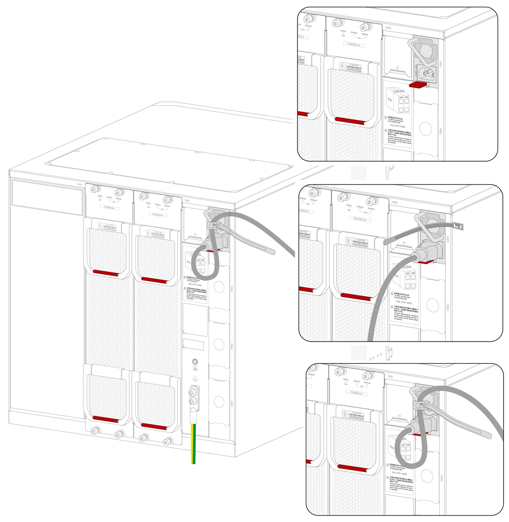
Connecting the power cord for a PSR1600-54A-B power supply
1. Connect the female connector of the power cord to the power receptacle on the PoE power supply.
2. Use a releasable cable tie or self-adhesive cable tie (provided with the power supply) to secure the power cord to the handle of the PoE power supply, as shown in Figure4-20.
3. Connect the other end of the power cord to an external power source.
Figure4-20 Connecting the power cord for a PSR1600-54A-B power supply (S10506X-G-PoE)

Installing transceiver modules and optical fibers
|
|
WARNING! Disconnected optical fibers or transceiver modules might emit invisible laser light. Do not stare into beams or view directly with optical instruments when the switch is operating. |
|
|
CAUTION: · Be careful not to touch the golden plating on a transceiver module during the installation process. · To avoid network cable damage and signal loss, do not strain or tangle a network cable. · Make sure the transceiver module is aligned correctly with the target port before pushing it into the port. · Make sure the two module ends of a network cable are compatible with the ports into which they will be inserted. |
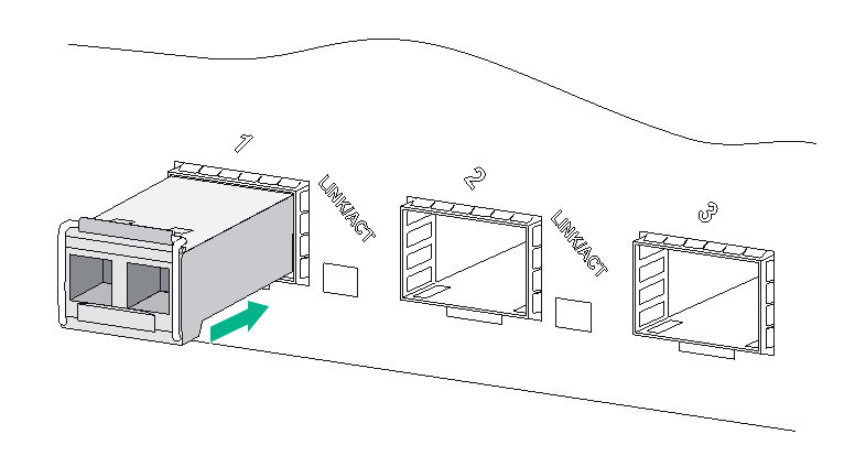
Installing an SFP/SFP+/SFP28/QSFP+/QSFP28/QSFP-DD transceiver module
|
|
CAUTION: · Read the following instructions before you install a transceiver module. Failure to follow these instructions might cause damage to the transceiver module. · Do not remove the dust plug from the transceiver module if you are not to connect an optical fiber to the module. · Before installing a transceiver module, remove the optical fiber (if any) from it. |
Two types of QSFP+ transceiver modules are available. One type uses a metal pull latch and the other uses a plastic pull latch. The installation procedure is the same for the two types of QSFP+ transceiver modules.
The installation procedure is similar for SFP, SFP+, SFP28, QSFP+, QSFP28, and QSFP-DD transceiver modules. The following procedure uses an SFP+ transceiver module as an example.
To install an SFP+ transceiver module:
1. Wear an ESD wrist strap. Make sure the wrist strap makes good skin contact and is reliably grounded. For more information, see "Attaching an ESD wrist strap."
2. Remove the dust plug from the target fiber port.
3. Unpack the SFP+ transceiver module. It comes with the bail latch catching the knob on the top of the transceiver module.
4. Hold the transceiver module by its two sides and align the module with the fiber port. Gently push the transceiver module into the port until it is firmly seated in the fiber port, as shown in Figure4-21.
Transceiver modules and fiber ports have disorientation rejection designs. If you cannot insert a transceiver module easily into a port, the orientation might be wrong. Remove and reorient the transceiver module.
In case of limited space, you can gently push against the front face of the transceiver module instead of the two sides.
5. Connect optical fibers to the transceiver module. For the connection procedure, see "Connecting the switch to the network through an optical fiber."
Figure4-21 Installing an SFP+ transceiver module
Connecting a network cable
|
|
CAUTION: · The bend radius of a DAC cable must be a minimum of 15 times the cable diameter. · The bend radius of an AOC cable must be a minimum of 20 times the cable diameter. |
The network cables are hot swappable.
To connect ports over a short distance, use network cables as follows:
· SFP+ DAC cable—Connects two SFP+ ports over a short distance.
· SFP28 DAC cable—Connects two SFP28 ports over a short distance.
· QSFP+ DAC or QSFP+ AOC cable—Connects two QSFP+ ports over a short distance.
· QSFP28 DAC or QSFP28 AOC cable—Connects two QSFP28 ports over a short distance.
· QSFP+ to SFP+ DAC cable—Connects one QSFP+ port to four SFP+ ports over a short distance.
· QSFP28 to SFP28 DAC cable—Connects one QSFP28 port to four SFP28 ports over a short distance.
· QSFP-DD DAC cable—Connects two QSFP-DD ports over a short distance.
The connection procedure is similar for these cables. The following connection procedure uses the SFP+ DAC cable as an example.
To connect an SFP+ DAC cable:
1. Wear an ESD wrist strap. Make sure the wrist strap makes good skin contact and is reliably grounded. For more information, see "Attaching an ESD wrist strap."
2. Remove the dust plug from the target fiber port.
3. Unpack the cable.
4. As shown in Figure4-22, align the module end of the cable with the fiber port and push it gently into the port until you feel it snaps into place.
Transceiver modules and fiber ports have disorientation rejection structures. If you cannot insert a transceiver module easily into a port, remove and reorient the transceiver module.
Figure4-22 Connecting an SFP+ DAC cable
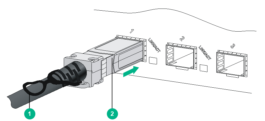
|
(1) Pull latch |
(2) Connector |
