- Table of Contents
-
- 13-WLAN advanced features
- 01-WLAN Probe Configuration Examples
- 02-Multicast Optimization Configuration Examples
- 03-Client Rate Limiting Configuration Examples
- 04-Inter-AC Roaming Configuration Examples
- 05-Inter-AC Roaming (IPv6) Configuration Examples
- 06-Inter-AC Roaming in Local Forwarding Mode Configuration Examples
- 07-H3C Access Controllers Cooperative Roaming for 802.11v Clients Configuration Examples
- 08-WLAN Load Balancing Configuration Examples
- 09-Static Blacklist Configuration Examples
- 10-Client Quantity Control Configuration Examples
- 11-AP License Synchronization Configuration Examples
- 12-BLE Module iBeacon Transmission Configuration Examples
- 13-Medical RFID Tag Management Configuration Examples
- 14-iBeacon Management Configuration Examples
- 15-Mesh Link Establishment Between Fit APs Configuration Examples
- 16-Mesh Link Establishment Between a Fit AP and a Fat AP Configuration Examples
- 17-Auto-DFS and Auto-TPC Configuration Examples
- 18-AP Image Downloading Configuration Examples
- 19-Dual-Uplink Interfaces Configuration Guide
- 20-H3C Comware AC Cloud-Managed AP Centralized Management Configuration Examples
- Related Documents
-
| Title | Size | Download |
|---|---|---|
| 13-Medical RFID Tag Management Configuration Examples | 94.36 KB |
|
|
|
H3C Access Controllers |
|
Medical RFID Tag Management |
|
Configuration Examples |
Copyright © 2023 New H3C Technologies Co., Ltd. All rights reserved.
No part of this manual may be reproduced or transmitted in any form or by any means without prior written consent of New H3C Technologies Co., Ltd.
Except for the trademarks of New H3C Technologies Co., Ltd., any trademarks that may be mentioned in this document are the property of their respective owners.
The information in this document is subject to change without notice.
Introduction
The following information provides an example for configuring WA4320i-X-R APs to realize medical RFID tag management.
Prerequisites
This document applies to Comware-based access controllers and access points. Procedures and information in the examples might be slightly different depending on the software or hardware version of the access controllers and access points.
The configuration examples in this document were created and verified in a lab environment, and all the devices were started with the factory default configuration. When you are working on a live network, make sure you understand the potential impact of every command on your network.
This document assumes that you have basic knowledge of IoT AP and WLAN location.
Example: Configuring medical RFID tag management
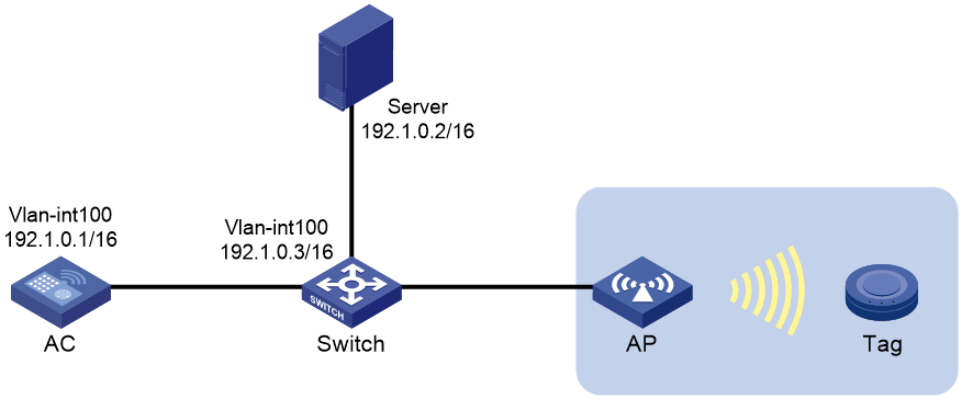
Network configuration
As shown in Figure 1, configure the AP to collect medical RFID tag information and send the information to the location server for calculation. Then, users can obtain tag information in various forms such as maps, tables, or reports.
Restrictions and guidelines
When you configure medical RFID tag management, follow these restrictions and guidelines:
· Use the actual serial ID of an AP to uniquely identify that AP.
· The port number of the location server configured on the AC must be the same as the port number specified on the location server.
Procedures
Configuring the AC
1. Configure interfaces on the AC:
# Create VLAN 100 and VLAN-interface 100, and assign an IP address to the VLAN interface. The AC will use this IP address to establish a CAPWAP tunnel with the AP.
<AC> system-view
[AC] vlan 100
[AC-vlan100] quit
[AC] interface vlan-interface 100
[AC-Vlan-interface100] ip address 192.1.0.1 16
[AC-Vlan-interface100] quit
# Configure GigabitEthernet 1/0/1 that connects the AC and the switch as a trunk port, and assign it to VLAN 100.
[AC] interface gigabitethernet 1/0/1
[AC-GigabitEthernet1/0/1] port link-type trunk
[AC-GigabitEthernet1/0/1] port trunk permit vlan 100
[AC-GigabitEthernet1/0/1] quit
2. Configure the AP:
|
|
NOTE: In a large-scale network, configure AP settings in AP group view instead of AP view as a best practice. |
# Create a manual AP named ap1, and specify the AP model and serial ID.
[AC] wlan ap ap1 model WA6320
[AC-wlan-ap-ap1] serial-id 219801A28N819CE0002T
# Create AP group group1, and configure a grouping rule by AP name to add AP ap1 to the group.
[AC] wlan ap-group group1
[AC-wlan-ap-group-group1] ap ap1
3. Configure a module:
# Enter the view of module 1.
[AC-wlan-ap-group-group1] ap-model WA6320
[AC-wlan-ap-group-group1-ap-model-WA6320] module 1
# Specify the supported module type as RFID for module 1, and enable module 1.
[AC-wlan-ap-group-group1-ap-model-WA6320-module-1] type rfid
[AC-wlan-ap-group-group1-ap-model-WA6320-module-1] module enable
[AC-wlan-ap-group-group1-ap-model-WA6320-module-1]quit
[AC-wlan-ap-group-group1-ap-model-WA6320]quit
4. Configure IoT location:
# Enable IoT location.
[AC-wlan-ap-group-group1] rfid-tracking iot enable
# Specify the IP address and port number of the IoT server.
[AC-wlan-ap-group-group1] iot engine-address 192.1.0.2 engine-port 3000
[AC-wlan-ap-group-group1] quit
Configuring the switch
1. Configure interfaces on the switch:
# Create VLAN 100 and VLAN-interface 100, and assign an IP address to the VLAN interface. The switch will use this VLAN to communicate with the AC.
<Switch> system-view
[Switch] vlan 100
[Switch-vlan100] quit
[Switch] interface vlan-interface 100
[Switch-Vlan-interface100] ip address 192.1.0.3 16
[Switch-Vlan-interface100] quit
# Configure GigabitEthernet 1/0/1 that connects the switch and the AC as a trunk port, and assign the trunk port to VLAN 100.
[Switch] interface gigabitethernet 1/0/1
[Switch-GigabitEthernet1/0/1] port link-type trunk
[Switch-GigabitEthernet1/0/1] port trunk permit vlan 100
[Switch-GigabitEthernet1/0/1] quit
# Configure GigabitEthernet 1/0/2 that connects the switch and the server as an access port, and assign the port to VLAN 100.
[Switch] interface gigabitethernet 1/0/2
[Switch-GigabitEthernet1/0/2] port link-type access
[Switch-GigabitEthernet1/0/2] port access vlan 100
[Switch-GigabitEthernet1/0/2] quit
# Configure GigabitEthernet 1/0/3 that connects the switch and AP as an access port, and assign the port to VLAN 100.
[Switch] interface gigabitethernet 1/0/3
[Switch-GigabitEthernet1/0/3] port link-type access
[Switch-GigabitEthernet1/0/3] port access vlan 100
# Enable PoE on GigabitEthernet 1/0/3.
[Switch-GigabitEthernet1/0/3] poe enable
[Switch-GigabitEthernet1/0/3] quit
2. Configure DHCP services:
# Enable DHCP.
[Switch] dhcp enable
# Create a DHCP address pool named 1 to assign an IP address to the AP.
[Switch] dhcp server ip-pool 1
# In DHCP address pool 1, specify subnet 192.1.0.0/16 for dynamic allocation, exclude IP addresses 192.1.0.1 and 192.1.0.2 from dynamic allocation, and specify the gateway IP address 192.1.0.3.
[Switch] dhcp server ip-pool 1
[Switch-dhcp-pool-1] network 192.1.0.0 mask 255.255.0.0
[Switch-dhcp-pool-1] forbidden-ip 192.1.0.1 192.1.0.2
[Switch-dhcp-pool-1] gateway-list 192.1.0.3
[Switch-dhcp-pool-1] quit
Verifying the configuration
# Verify that the type of module 1 is RFID and the module is enabled.
[AC] display wlan module-information ap ap1 module 1
Module administrative type : RFID
Module physical type : IOT
Model : RFID
HW version : 12090031
SW version : 12090202
Serial ID : 0000051700000042
Module MAC : d461-fefd-0368
Module physical status : Normal
Module administrative status : Enabled
Description :Not configured
# Verify that you can view tag information collected by the AP on the location server.
Configuration files
· AC:
#
vlan 100
#
interface Vlan-interface100
ip address 192.1.0.1 255.255.0.0
#
interface GigabitEthernet1/0/1
port link-type trunk
port trunk permit vlan 100
#
wlan ap-group group1
ap ap1
rfid-tracking iot enable
iot engine-address 192.1.0.2 engine-port 3000
ap-model WA6320
module 1
type rfid
module enable
#
wlan ap ap1 model WA6320
serial-id 219801A28N819CE0002T
#
· Switch:
#
dhcp enable
#
vlan 100
#
dhcp server ip-pool 1
gateway-list 192.1.0.3
network 192.1.0.0 mask 255.255.0.0
forbidden-ip 192.1.0.1
forbidden-ip 192.1.0.2
#
interface Vlan-interface100
ip address 192.1.0.3 255.255.0.0
#
interface GigabitEthernet1/0/1
port link-type trunk
port trunk permit vlan 100
#
interface GigabitEthernet1/0/2
port access vlan 100
#
interface GigabitEthernet1/0/3
port access vlan 100
poe enable
#
Related documentation
· Internet of Things Command Reference in H3C Access Controllers Command References
· Internet of Things Configuration Guide in H3C Access Controllers Configuration Guides
· WLAN Advanced Features Command Reference in H3C Access Controllers Command References
· WLAN Advanced Features Configuration Guide in H3C Access Controllers Configuration Guides
