- Table of Contents
-
- 13-WLAN advanced features
- 01-WLAN Probe Configuration Examples
- 02-Multicast Optimization Configuration Examples
- 03-Client Rate Limiting Configuration Examples
- 04-Inter-AC Roaming Configuration Examples
- 05-Inter-AC Roaming (IPv6) Configuration Examples
- 06-Inter-AC Roaming in Local Forwarding Mode Configuration Examples
- 07-H3C Access Controllers Cooperative Roaming for 802.11v Clients Configuration Examples
- 08-WLAN Load Balancing Configuration Examples
- 09-Static Blacklist Configuration Examples
- 10-Client Quantity Control Configuration Examples
- Related Documents
-
| Title | Size | Download |
|---|---|---|
| 03-Client Rate Limiting Configuration Examples | 79.23 KB |
|
|
|
H3C Access Controllers |
|
Client Rate Limiting Configuration Examples |
|
|
Copyright © 2023 New H3C Technologies Co., Ltd. All rights reserved.
No part of this manual may be reproduced or transmitted in any form or by any means without prior written consent of New H3C Technologies Co., Ltd.
Except for the trademarks of New H3C Technologies Co., Ltd., any trademarks that may be mentioned in this document are the property of their respective owners.
The information in this document is subject to change without notice.
Introduction
The following information provides an example for configuring client rate limiting.
Prerequisites
This document applies to Comware-based access controllers and access points. Procedures and information in the examples might be slightly different depending on the software or hardware version of the access controllers and access points.
The configuration examples in this document were created and verified in a lab environment, and all the devices were started with the factory default configuration. When you are working on a live network, make sure you understand the potential impact of every command on your network.
This document assumes that you have basic knowledge of client rate limiting.
Example: Configuring client rate limiting
Network configuration
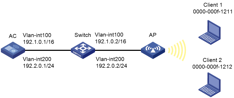
As shown in Figure 1, the switch acts as a DHCP server to assign IP addresses to the AP and the clients. The AC forwards client traffic. Configure service-template-based client rate limiting to limit both the incoming and outgoing traffic rates to 6000 Kbps in dynamic mode.
Restrictions and guidelines
Use the serial ID labeled on the AP's rear panel to specify an AP.
Procedures
Configuring the AC
1. Configure interfaces on the AC:
# Create VLAN 100 and VLAN-interface 100, and assign an IP address to the VLAN interface. The AC will use this IP address to establish a CAPWAP tunnel with the AP.
<AC> system-view
[AC] vlan 100
[AC-vlan100] quit
[AC] interface vlan-interface 100
[AC-Vlan-interface100] ip address 192.1.0.1 16
[AC-Vlan-interface100] quit
# Create VLAN 200 and VLAN-interface 200, and assign an IP address to the VLAN interface. The AC will use VLAN 200 for client access.
[AC] vlan 200
[AC-vlan200] quit
[AC] interface vlan-interface 200
[AC-Vlan-interface200] ip address 192.2.0.1 24
[AC-Vlan-interface200] quit
# Configure GigabitEthernet 1/0/1 that connects the AC and the switch as a trunk port, and assign it to VLANs 1, 100, and 200.
[AC] interface gigabitethernet 1/0/1
[AC-GigabitEthernet1/0/1] port link-type trunk
[AC-GigabitEthernet1/0/1] port trunk permit vlan 1 100 200
[AC-GigabitEthernet1/0/1] quit
2. Configure wireless services:
# Create a service template named service and enter its view.
[AC] wlan service-template service
# Configure the SSID of service template service as service.
[AC-wlan-st-service] ssid service
# Assign clients coming online through the service template to VLAN 200.
[AC-wlan-st-service] vlan 200
# Specify the AKM mode as PSK, and specify plaintext string 12345678 as the preshared key.
[AC-wlan-st-service] akm mode psk
[AC-wlan-st-service] preshared-key pass-phrase simple 12345678
# Specify the cipher suite as CCMP and the security IE as RSN.
[AC-wlan-st-service] cipher-suite ccmp
[AC-wlan-st-service] security-ie rsn
# Configure the AC to forward client data traffic. You can skip this step if the AC is the client traffic forwarder by default.
[AC-wlan-st-service] client forwarding-location ac
# Limit the client traffic rate in both directions to 6000 Kbps in dynamic mode, and enable client rate limiting for service template service.
[AC-wlan-st-service] client-rate-limit inbound mode dynamic cir 6000
[AC-wlan-st-service] client-rate-limit outbound mode dynamic cir 6000
# Enable the service template.
[AC-wlan-st-1] service-template enable
[AC-wlan-st-1] quit
3. Configure the AP:
|
|
NOTE: In large-scale networks, configure AP groups instead of single APs as a best practice. |
# Create a manual AP named officeap, and specify the model and serial ID.
[AC] wlan ap officeap model WA6320
[AC-wlan-ap-officeap] serial-id 219801A28N819CE0002T
# Create AP group group1, add the AP to the AP group, and specify the AP model.
[AC] wlan ap-group group1
[AC-wlan-ap-group-group1] ap officeap
[AC-wlan-ap-group-group1] ap-model WA6320
# Enter the view of radio 1.
[AC-wlan-ap-group-group1-ap-model-WA6320] radio 1
# Bind service template service to radio 1, and enable radio 1.
[AC-wlan-ap-group-group1-ap-model-WA6320-radio-1] service-template service
[AC-wlan-ap-group-group1-ap-model-WA6320-radio-1] radio enable
[AC-wlan-ap-group-group1-ap-model-WA6320-radio-1] quit
[AC-wlan-ap-group-group1-ap-model-WA6320] quit
[AC-wlan-ap-group-group1] quit
Configuring the switch
# Create VLAN 100. The switch will use this VLAN to forward the traffic on the CAPWAP tunnel between the AC and AP.
<Switch> system-view
[Switch] vlan 100
[Switch-vlan100] quit
# Create VLAN 200. The switch will use this VLAN to forward client traffic.
[Switch] vlan 200
[Switch-vlan200] quit
# Configure GigabitEthernet 1/0/1 that connects the switch and the AC as a trunk port, and assign the trunk port to VLANs 1, 100, and 200.
[Switch] interface gigabitethernet 1/0/1
[Switch-GigabitEthernet1/0/1] port link-type trunk
[Switch-GigabitEthernet1/0/1] port trunk permit vlan 1 100 200
[Switch-GigabitEthernet1/0/1] quit
# Configure GigabitEthernet 1/0/2 that connects the switch and the AP as an access port, and assign the access port to VLAN 100.
[Switch] interface gigabitethernet 1/0/2
[Switch-GigabitEthernet1/0/2] port link-type access
[Switch-GigabitEthernet1/0/2] port access vlan 100
# Enable PoE on GigabitEthernet 1/0/2.
[Switch-GigabitEthernet1/0/2] poe enable
[Switch-GigabitEthernet1/0/2] quit
# Create VLAN-interface 100, and assign an IP address to the VLAN interface.
[Switch] interface vlan-interface 100
[Switch-Vlan-interface100] ip address 192.1.0.2 16
[Switch-Vlan-interface100] quit
# Create VLAN-interface 200, and assign an IP address to the VLAN interface.
[Switch] interface vlan-interface 200
[Switch-Vlan-interface200] ip address 192.2.0.2 24
[Switch-Vlan-interface200] quit
# Enable DHCP.
[Switch] dhcp enable
# Configure DHCP pool 100 to assign an IP address to the AP.
[Switch] dhcp server ip-pool 100
[Switch-dhcp-pool-100] network 192.1.0.0 mask 255.255.0.0
[Switch-dhcp-pool-100] gateway-list 192.1.0.1
[Switch-dhcp-pool-100] quit
# Configure DHCP pool 200 to assign an IP address to clients. Specify the gateway address and DNS server address. In this example, the gateway also acts as a DNS server.
[Switch] dhcp server ip-pool 200
[Switch-dhcp-pool-200] network 192.2.0.0 mask 255.255.255.0
[Switch-dhcp-pool-200] gateway-list 192.2.0.1
[Switch-dhcp-pool-200] dns-list 192.2.0.1
[Switch-dhcp-pool-200] quit
Verifying the configuration
# Verify that the incoming and outgoing traffic rates of client 1 and client 2 are both limited within 3000 Kbps. (Details not shown.)
Configuration files
· AC:
#
vlan 100
#
vlan 200
#
wlan service-template service
ssid service
vlan 200
akm mode psk
preshared-key pass-phrase simple 12345678
cipher-suite ccmp
security-ie rsn
client forwarding-location ac
client-rate-limit inbound mode dynamic cir 6000
client-rate-limit outbound mode dynamic cir 6000
service-template enable
#
interface Vlan-interface100
ip address 192.1.0.1 255.255.0.0
#
interface Vlan-interface200
ip address 192.2.0.1 255.255.255.0
#
interface GigabitEthernet1/0/1
port link-type trunk
port trunk permit vlan 1 100 200
#
wlan ap officeap model WA6320
serial-id 219801A28N819CE0002T
#
wlan ap-group group1
ap officeap
ap-model WA6320
radio 1
service-template service
radio enable
#
· Switch:
#
vlan 100
#
vlan 200
#
dhcp server ip-pool 100
gateway-list 192.1.0.1
network 192.1.0.0 mask 255.255.0.0
#
dhcp server ip-pool 200
gateway-list 192.2.0.1
network 192.2.0.0 mask 255.255.255.0
dns-list 192.2.0.1
#
interface Vlan-interface100
ip address 192.1.0.2 255.255.0.0
#
interface Vlan-interface200
ip address 192.2.0.2 255.255.255.0
#
interface GigabitEthernet1/0/1
port link-type trunk
port trunk permit vlan 1 100 200
#
interface GigabitEthernet1/0/2
port link-type access
port access permit vlan 100
poe enable
#
Related documentation
· QoS Command Reference in H3C Access Controllers Command References
· QoS Configuration Guide in H3C Access Controllers Configuration Guides
