- Table of Contents
-
- 14-High Availability Configuration Guide
- 00-Preface
- 01-Ethernet OAM configuration
- 02-CFD configuration
- 03-DLDP configuration
- 04-Monitor Link configuration
- 05-S-Trunk configuration
- 06-Error code detection configuration
- 07-VRRP configuration
- 08-VSRP configuration
- 09-Failover group configuration
- 10-Service instance group configuration
- 11-BFD configuration
- 12-Track configuration
- 13-Process placement configuration
- Related Documents
-
| Title | Size | Download |
|---|---|---|
| 09-Failover group configuration | 73.77 KB |
Failover group operating mechanism
Restrictions and guidelines: failover group configuration
Prerequisites for failover group configuration
Configuring intra-system service backup
Configuring inter-system service backup
Display and maintenance commands for failover groups
Configuring failover groups
About failover groups
A failover group backs up services (such as NAT) between two CPUs to ensure service continuity. A CPU is also named a node in this chapter.
Failover group operating mechanism
A failover group contains a primary node and a secondary node. When a failover group is used by a service module, the primary node processes services and backs up service data to the secondary node. The secondary node does not process services, but it takes over the services when the primary node fails. When the primary node is recovered, traffic is switched to the primary node again.
For more information about the service modules that can use a failover group, see the configuration guides for specific modules.
A failover group can be deployed on one system or two independent systems for intra-system service backup or inter-system service backup. The two deployment plans use different methods to determine whether a node is a primary node or a secondary node. A system refers to the system operating on a single device or the IRF system formed by multiple devices.
Intra-system service backup
To use intra-system service backup, you must specify the primary node and the secondary node by using the bind command when you deploy a failover group.
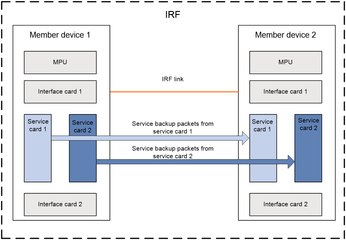
Figure 1 shows the service backup between two service cards on a single physical device. Figure 2 shows the service backup between two service cards in an IRF system.
Figure 1 Service backup on a single physical device
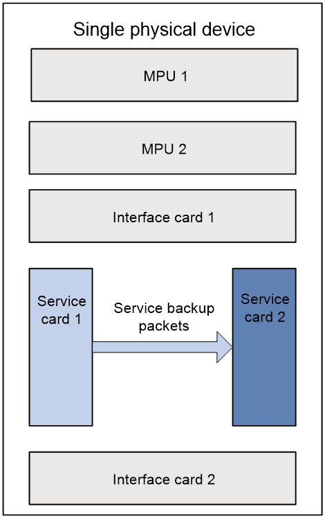
Figure 2 Service backup in an IRF system
Inter-system service backup
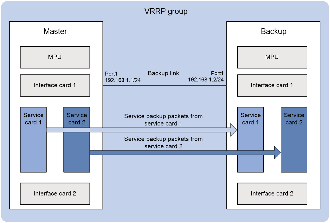
To deploy a failover group on two independent systems, you must add the two systems to a VRRP group and bind the failover group to the VRRP group. VRRP determines the status of the nodes in the failover group The node on the master of the VRRP group is the primary node. The node on the backup of the VRRP group is the secondary node. The node on the master sends backup packets to the node on the backup through a Layer 3 link, as shown in Figure 3. When the master fails, the node on the newly-elected master takes over the primary role. For more information about VRRP, see "Configuring VRRP."
Figure 3 Inter-system service backup
Backup types
You can create one, two, or multiple failover groups to achieve the following backup types:
· One failover group—The primary node processes services and backs up service data to the secondary node.
· Two failover groups—The primary node and the secondary node in one failover group act as the secondary node and the primary node in the other failover group. Both nodes can process services and back up service data to each other.
· Multiple failover groups—You create multiple failover groups in different ways to implement the following group types:
¡ Each failover group has its own primary node and all the failover groups share the same secondary node. All the primary nodes back up service data to the same secondary node.
¡ Each node acts as the primary node in one failover group and the secondary node in another group to implement load sharing. However, any two groups cannot have the same primary and secondary node pairs. For example, you want nodes 1, 2, and 3 to back up one another. You must create three failover groups and configure nodes 1 and 2, nodes 2 and 3, and nodes 3 and 1 as the primary and secondary nodes in the three failover groups, respectively.
Restrictions and guidelines: failover group configuration
The failover group feature is supported only by the IM-MSUX and IM-MSEX-B cards. The IM-MSEX-B card has multiple CPUs, and you must specify a CPU number when you assign a CPU on that card to a failover group. The IM-MSEX-B card has only one CPU, and you do not need to specify a CPU number when you assign the CPU on that card to a failover group.
Prerequisites for failover group configuration
Finish the configuration for service modules and enable backup of these services.
Configuring intra-system service backup
1. Enter system view.
system-view
2. Create a failover group and enter its view.
failover group group-name [ id group-id ]
By default, no failover groups exist.
The id group-id option is required when you create a failover group. It is optional when you enter failover group view.
3. Assign a node to the failover group.
In standalone mode:
bind slot slot-number cpu cpu-number { primary | secondary }
In IRF mode:
bind chassis chassis-number slot slot-number cpu cpu-number { primary | secondary }
By default, a failover group has no nodes.
Different failover groups cannot share the same primary node. The primary node and the secondary node in a failover group cannot be the same node, and they cannot be different CPUs on the same card.
Configuring inter-system service backup
Restrictions and guidelines
Please configure this feature on two systems respectively and follow these restrictions and guidelines:
· Configure the same failover group name and group ID for the two systems.
· You must execute the remote-backup command on both of the systems and configure the same port number for them. As a best practice, use a direct link for backup packets. If the physical interface on the link transmits multiple types of traffic, create a dedicated subinterface for each kind of traffic.
· You cannot bind a failover group to a VRRP group if the following conditions exist:
¡ The failover group is associated with a service instance group.
¡ The service instance group is used by a NAT instance configured with load sharing or bound to a static address pool.
Prerequisites
· Set up the backup link by using two Layer 3 interfaces that can reach each other.
· First complete the related VRRP configuration.
· Configure the interface identification code by using the identity-number command to identify the interfaces that back up services between two systems. Log in to the two systems and configure the same identification code for the two interfaces. Inconsistent interface identification codes can cause backup failure. For more information about the identity-number command, see session management commands in Security Command Reference.
Procedure
1. Enter system view.
system-view
2. Create a failover group and enter its view.
failover group group-name id group-id
failover group group-name [ id group-id ]
By default, no failover groups exist.
The id group-id option is required when you create a failover group. It is optional when you enter failover group view.
3. Assign a node to the failover group.
In standalone mode:
bind slot slot-number cpu cpu-number vrrp
In IRF mode:
bind chassis chassis-number slot slot-number cpu cpu-number vrrp
By default, a failover group has no nodes.
4. Specify a backup channel for inter-system service backup.
remote-backup local ip-address peer peer-ip-address port port-number
By default, no backup channel is specified for inter-system service backup.
5. Bind the failover group to a VRRP group.
bind-vrrp virtual-router-id interface interface-type interface-number
By default, a failover group is not bound to any VRRP group.
Display and maintenance commands for failover groups
Execute display commands in any view.
|
Task |
Command |
|
Display failover group information. |
display failover { group [ group-name ] | group-name group-name } |
