- Table of Contents
-
- 06-Network
- 01-VRF
- 02-Interface
- 03-Interface pairs
- 04-Interface collaboration
- 05-4G
- 06-Security zones
- 07-VLAN
- 08-MAC
- 09-DNS
- 10-ARP
- 11-ND
- 12-GRE
- 13-IPsec
- 14-ADVPN
- 15-L2TP
- 16-SSL VPN
- 17-Routing table
- 18-Static routing
- 19-Policy-based routing
- 20-OSPF
- 21-BGP
- 22-RIP
- 23-IP multicast routing
- 24-PIM
- 25-IGMP
- 26-DHCP
- 27-HTTP
- 28-SSH
- 29-NTP
- 30-FTP
- 31-Telnet
- 32-MAC authentication
- 33-MAC address whitelist
- 34-MAC access silent MAC info
- 35-MAC access advanced settings
- 36-IP authentication
- 37-IPv4 whitelist
- 38-IPv6 whitelist
- 39-Wireless
- Related Documents
-
| Title | Size | Download |
|---|---|---|
| 15-L2TP | 63.63 KB |
This help contains the following topics:
¡ Typical L2TP network components
Introduction
The Layer 2 Tunneling Protocol (L2TP) is a Virtual Private Dialup Network (VPDN) tunneling protocol. L2TP sets up point-to-point tunnels across a public network (for example, the Internet) and transmits encapsulated PPP frames (L2TP packets) over the tunnels. With L2TP, remote users can access the private networks through L2TP tunnels after connecting to a public network by using PPP.
Typical L2TP network components
A typical L2TP network has the following components:
· Remote system—A remote system is usually a remote user's host or a remote branch's device that needs to access the private network.
· LAC—An L2TP access concentrator (LAC) is both PPP and L2TP capable. It is usually a network access server (NAS) located at a local ISP, which provides access services mainly for PPP users.
An LAC is an endpoint of an L2TP tunnel and lies between an LNS and a remote system. It encapsulates packets received from a remote system by using L2TP and then sends the encapsulated packets to the LNS. It decapsulates packets received from the LNS and then sends the decapsulated packets to the intended remote system.
· LNS—An L2TP network server (LNS) is both PPP and L2TP capable. It is usually an edge device on an enterprise network.
An LNS is the other endpoint of an L2TP tunnel. It is the logical termination point of a PPP session tunneled by the LAC. L2TP extends the termination point of a PPP session from a NAS to an LNS by establishing a tunnel.
L2TP tunneling modes
L2TP tunneling modes include NAS-initiated, client-initiated, and LAC-auto-initiated.
NAS-initiated tunneling mode
As shown in Figure 1, a remote system dials in to the LAC through a PPPoE/ISDN network. The LAC initiates a tunneling request to the LNS over the Internet.
Figure 1 NAS-initiated tunneling mode

A NAS-initiated tunnel has the following characteristics:
· The remote system only needs to support PPP, and it does not need to support L2TP.
· Authentication and accounting of the remote system can be implemented on the LAC or LNS.
Client-initiated tunneling mode
As shown in Figure 2, a remote system running L2TP (LAC client) has a public IP address to communicate with the LNS through the Internet. The LAC client can directly initiate a tunneling request to the LNS without any dedicated LAC devices.
Figure 2 Client-initiated tunneling mode
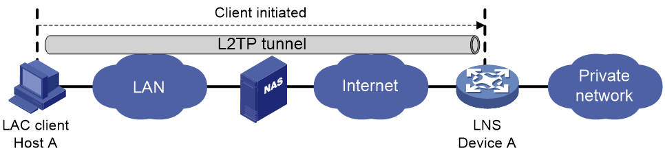
A client-initiated tunnel has the following characteristics:
· A client-initiated tunnel has higher security because it is established between a remote system and the LNS.
· The remote system must support L2TP and be able to communicate with the LNS. This causes poor expandability.
LAC-auto-initiated tunneling mode
In NAS-initiated mode, a remote system must successfully dial in to the LAC through PPPoE or ISDN.
In LAC-auto-initiated mode, you can configure tunnel settings on the LAC to trigger the LAC to initiate a tunneling request to the LNS. When a remote system accesses the private network, the LAC forwards data through the L2TP tunnel.
Figure 3 LAC-auto-initiated tunneling mode

An LAC-auto-initiated tunnel has the following characteristics:
· The connection between a remote system and the LAC is not confined to a dial-up connection and can be any IP-based connection.
· You do not need to trigger L2TP tunnel establishment by dialup on the remote system.
· An L2TP session is established immediately after an L2TP tunnel is established. Then, the LAC and LNS, acting as the PPPoE client and PPPoE server, respectively, perform PPP negotiation.
· An L2TP tunnel can carry only one L2TP session.
· The LNS assigns a private IP address to the LAC instead of to the remote system.
Troubleshooting L2TP
Tunnel setup failure
Symptom
After you select VPN > L2TP > TunnelInfo, no tunnel information is displayed. Tunnel establishment fails.
Solution
To resolve the problem, verify the following items to avoid tunnel setup failures:
· The address of the LNS is configured correctly on the LAC.
· The same PPP authentication mode is configured for the LAC and the LNS.
· Usernames and passwords are correctly configured on the LAC and the LNS.
· If the L2TP group number is not 1 on the LNS, the same tunnel name is configured for the LAC and the LNS.
· Tunnel authentication succeeds.
You can enable tunnel authentication on both sides or either side. To ensure a successful tunnel establishment when tunnel authentication is enabled on both sides or either side, set the same non-null key on the LAC and the LNS.
Data transmission failure
Symptom
After you select VPN > L2TP > TunnelInfo, the page shows that tunnels are successfully established. However, data transmission fails. For example, the LAC and LNS cannot ping each other.
Solution
To resolve the problem:
1. Verify that the LAC has a route to the private network behind the LNS, and vice versa. If no route is available, configure a static route or a dynamic routing protocol.
2. Add the Virtual-Template interface on the LNS to a security zone, and permit the traffic from the security zone to security zone Local.
3. Increase the link bandwidth to enhance the link availability.
Internet backbone congestion and high packet loss ratio might cause data transmission failures. L2TP data transmission is based on UDP, which does not provide the packet error control feature. If the line is unstable, the LAC and LNS might be unable to ping each other.
