- Table of Contents
-
- 07-System
- 01-Hot backup
- 02-VRRP
- 03-Track
- 04-BFD
- 05-NQA
- 06-Basic log settings
- 07-Email server
- 08-Session log settings
- 09-NAT log settings
- 10-AFT log settings
- 11-Sandbox log settings
- 12-Threat log settings
- 13-Application audit log settings
- 14-NetShare log settings
- 15-URL filtering log settings
- 16-Data filtering log settings
- 17-Attack defense log settings
- 18-Reputation log settings
- 19-Bandwidth alarm logs
- 20-Configuration log settings
- 21-Security policy log
- 22-File filtering log settings
- 23-Terminal identification logging
- 24-Heartbeat log settings
- 25-WAF log settings
- 26-IP access logs
- 27-MAC access log
- 28-Load balancing logging
- 29-Bandwidth management logs
- 30-Context rate limit logging
- 31-Zero trust logs
- 32-Report settings
- 33-Session settings
- 34-Signature upgrade
- 35-Software upgrade
- 36-License management
- 37-IRF
- 38-IRF advanced settings
- 39-Contexts
- 40-vSystems
- 41-Administrators
- 42-Date and time
- 43-MAC address learning through a Layer 3 device
- 44-SNMP
- 45-Configuration management
- 46-Reboot
- 47-About
- 48-Fast Internet Access
- 49-Content moderation log settings
- 50-Drop statistics
- 51-License server
- Related Documents
-
| Title | Size | Download |
|---|---|---|
| 01-Hot backup | 193.26 KB |
Hot backup
This help contains the following topics:
¡ Basic concepts in hot backup configuration
¡ Configuration consistency check
¡ Hot backup in collaboration with VRRP
¡ Hot backup in collaboration with routing protocols
¡ Transparent in-path deployment of the hot backup member devices
Introduction
Hot backup is a device-level high availability solution. It enables two devices to back up each other dynamically to ensure user service continuity upon failure of one of the devices.
Hot backup works with Remote Backup Management (RBM) to manage multiple VRRP groups or adjust the link costs for routing protocols on two member devices to ensure that the devices have consistent roles and states. Hot backup can synchronize important configuration and service entries between the devices to ensure service continuity. Two devices must have the same software and hardware environments for hot backup.
Basic concepts in hot backup configuration
Basic concepts in hot backup configuration are as follows:
· Primary and secondary roles—Control the direction of configuration synchronization between devices. The primary and secondary roles are assigned to the two devices for hot backup, respectively. The primary device synchronizes its configuration to the secondary device, and the configuration on the secondary device is overwritten.
· Active and standby states—Determine which device forwards and processes traffic in the data plane. The active device forwards traffic of services and backs up service entries to the standby device in real time. When the active device fails, the standby device takes over the active role to ensure service continuity.
· VRRP active and standby groups—Associate hot backup with VRRP so as to use hot backup to centrally manage the status of multiple VRRP groups.
· RBM channels—Transmit status information, important configuration, and service entries between the hot backup members.
· Hot backup operating modes—Include active/standby mode and dual-active mode. In active/standby mode, the active device processes all services. In dual-active mode, both devices process services to increase the hot backup capability and load share traffic.
· RBM packets—Transmitted through TCP over the RBM channel between the hot backup members.
Hot backup operating modes
The active/standby and dual-active modes are supported for hot backup.
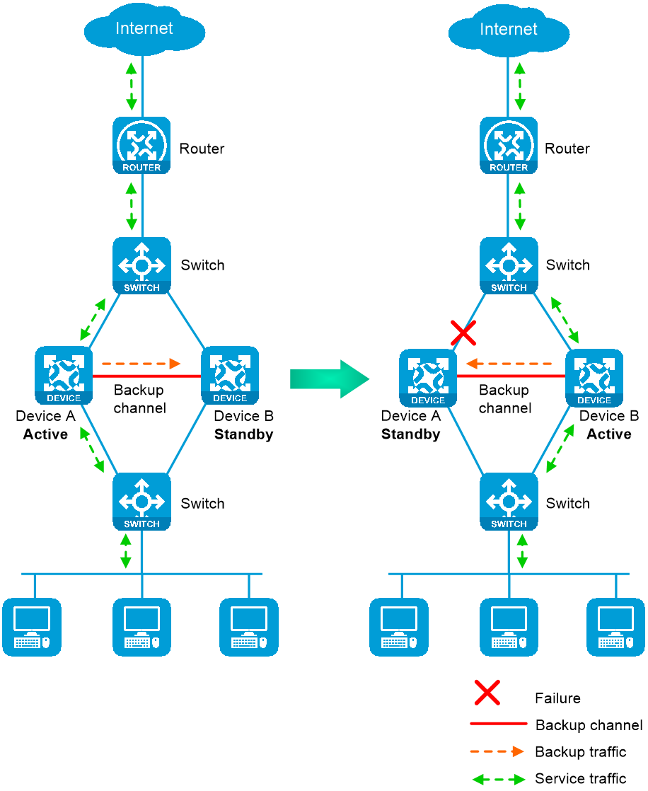
Active/standby mode
In active/standby mode, one device is active to process services, and the other device stands by, as shown in Figure 1. When an interface or link on the active device fails or when the active device fails, the standby device becomes active to process services.
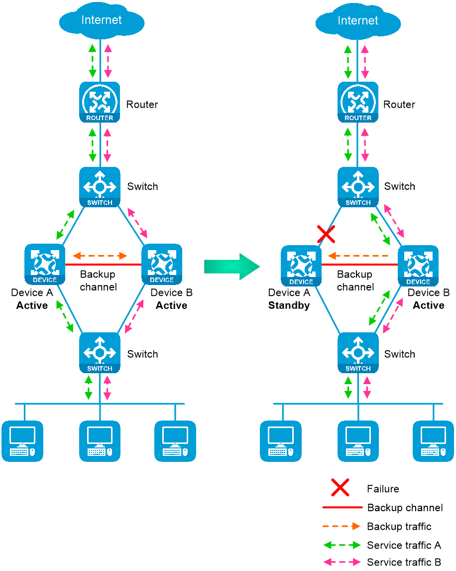
Dual-active mode
In dual-active mode, both devices process services to increase hot backup capability, as shown in Figure 2. When one device fails, its traffic is switched to the other device for forwarding.
RBM channels
Overview
The hot backup members transmit hot backup status, important configuration, and service entries over the following channels:
· Control channel—Transmits data by using packets, including hot backup status packets, configuration consistency check packets, backup packets for service entries, data packets that require transparent transmission, and configuration synchronization packets.
· Data channel—Transmits only backup packets and packets that require transparent transmission. The data channel uses the hardware driver for data transmission and supports only Layer 2 forwarding.
Establishment and keepalive mechanism of the control channel
The control channel uses the keepalive mechanism of TCP for reachability detection. The control channel is established through TCP. The device with the higher IP address acts as the server, and the other device acts as the client to initiate the TCP connection.
Each member device periodically sends keepalive packets to the peer device over the RBM channel. If a device has not received any responses from the peer when the maximum number of keepalive attempts is reached, the RBM channel is disconnected.
Service entry backup
Overview
A hot backup backs up the service entries generated on the active device to the standby device to prevent service interruption when an active/standby switchover occurs.
Security devices like firewalls generate a session entry for each dynamic connection. In hot backup, only the active device processes traffic and generates session entries. To ensure service continuity, the active device backs up its session entries to the standby device in real time. After an active/standby switchover, the new active device can forward the packets of the existing services based on the session entries without interruption.
Supported services
The hot backup member devices can perform hot backup for the following service entries:
· Session entries.
· Session relation entries.
· NAT port blocks.
· AFT port blocks.
· Entries generated by security service modules.
Support for these entries depends on the device model.
Configuration backup
Overview
A hot backup backs up important configuration from the primary device to the secondary device to prevent service interruption when an active/standby switchover occurs. The configuration on the secondary device is overwritten. The unidirectional backup mechanism avoids configuration conflicts, especially in dual-active mode. The roles of the hot backup member devices can only be manually assigned to devices. As a best practice to ensure correct hot backup operation, enable configuration backup on the primary device.
Backup type
The hot backup member devices support both automatic backup and manual backup.
Supported services
The hot backup member devices can perform configuration backup for the following services:
· Resources: VPN instance, ACL, object group, time range, security zone, session management, APR, AAA.
· DPI: Application layer inspection engine, IPS, URL filter, data filter, file filter, anti-virus, data analysis center, WAF.
· Policies: Object policy, security policy, ASPF, attack detection and prevention, connection limit, NAT, AFT, load balancing, bandwidth management, application auditing and management, shared network access management, proxy policy.
· Logs: Fast log output, flow log.
· SSL VPN.
· VLAN.
· Information center.
Support for these services depends on the device model.
Configuration consistency check
The hot backup member devices verify configuration consistency between them by using configuration consistency check packets. If a device detects configuration inconsistency, it generates a log for you to manually synchronize configuration.
Hot backup in collaboration with VRRP
Overview
You can use hot backup and VRRP in combination to control master/backup switchover for device role consistency (master or backup) in multiple VRRP groups. This ensures that both inbound and outbound traffic can be switched to the new master for symmetric forwarding upon device failure.
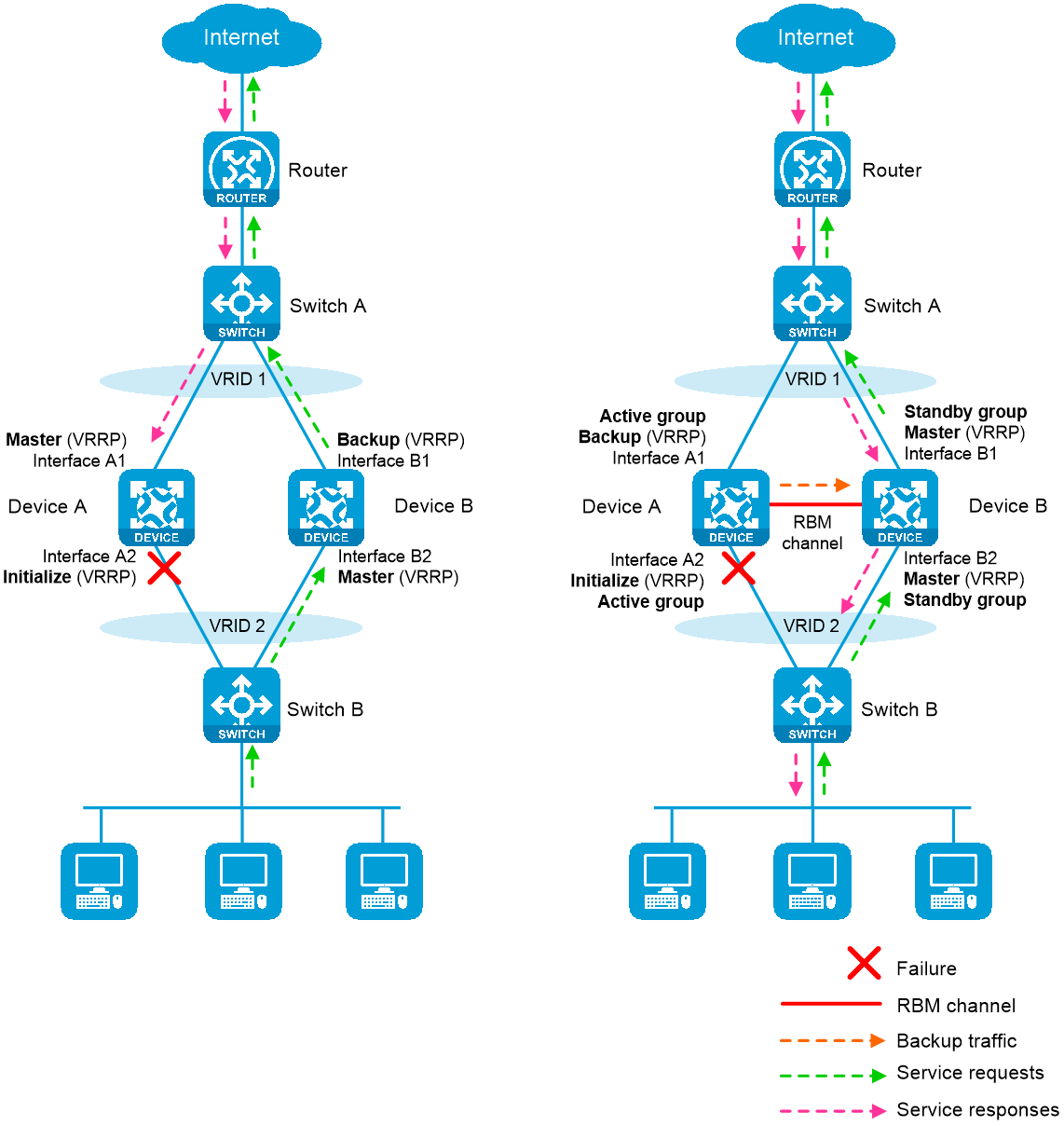
Figure 3 illustrates VRRP association with hot backup in active/standby mode.
· As shown in the left, VRRP cannot ensure symmetric forwarding upon failure on a device, which causes traffic interruption.
· As shown in the right, after the RBM channel is established, the hot backup configuration determines the roles of the devices in all VRRP groups. The master election mechanism of VRRP no longer takes effect. If the RBM channel is disconnected, the master election mechanism of VRRP takes effect again.
Figure 3 Hot backup in collaboration with VRRP
VRRP active/standby group
Hot backup is associated with VRRP by VRRP active and standby groups.
A VRRP active/standby group can be in master or backup state, which determines the state of devices in the associated VRRP groups. For example, if a VRRP active group is in master state, all devices in the associated VRRP groups are masters.
The initial state of a VRRP active/standby group is as follows:
· Active/Standby mode—On the primary device, the initial state is master for the VRRP active and standby groups. On the secondary device, the initial state is backup for the VRRP active and standby groups.
· Dual-active mode—The state of a VRRP active/standby group is not affected by the roles of the hot backup member devices. The initial state is master for the VRRP active group and is backup for the VRRP standby group.
VRRP master election in hot backup environment
After hot backup is associated with VRRP, the hot backup configuration determines the roles of the devices in the VRRP groups. As shown in Figure 3, Device A is the master in VRRP group 1 and VRRP group 2, and Device B is the backup in VRRP group 1 and VRRP group 2. When Interface A2 on Device A fails, the following events occur:
1. Device A receives an interface failure event and sends the status change information of the VRRP active and standby groups to Device B.
2. Device B sets its role to master in the VRRP standby group and then becomes the master in VRRP group 1 and VRRP group 2.
3. Device B sends a response to Device A after the master/backup switchover.
4. Device A sets its role to backup in the VRRP active group and then becomes the backup in VRRP group 1 and VRRP group 2.
5. When Interface A2 recovers, the hot backup member devices perform another master/backup switchover following the same procedure. Traffic is switched back to Device A after the switchover.
ARP and MAC learning in VRRP
When the members of a VRRP group receive an ARP request for the group's virtual IP address, the master replies with the group's virtual MAC address. This allows the upstream and downstream Layer 2 devices and hosts to learn the virtual MAC address.
Hot backup in collaboration with routing protocols
Overview
You can use hot backup to enable the routing protocols on the standby device to advertise modified link cost. The feature ensures that both inbound and outbound traffic can be switched to the new active device for symmetric forwarding.
To use hot backup with routing protocols, you must use track entries to monitor the status of uplink and downlink interfaces for the hot backup member devices to perform an active/standby switchover when link or interface failure occurs.
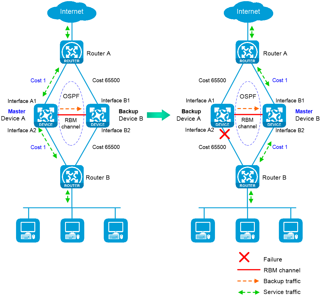
The following information uses OSPF on the hot backup member devices in active/standby mode to describe how hot backup collaborates with dynamic routing protocols:
· As shown in Figure 4, when both Device A (active) and Device B (standby) are operating correctly, Device A advertises the original link cost 1, and Device B advertises the adjusted link cost 65500. As a result, Device A forwards all traffic that traverses the hot backup member devices.
· As shown in Figure 4, when downlink Interface A2 of Device A fails, Device A and Device B switch their states. Then, Device B (active) advertises the original link cost 1, and Device A (standby) advertises the adjusted link cost 65500. As a result, Device B forwards all traffic that traverses the hot backup member devices.
Figure 4 Hot backup in collaboration with routing protocols
Mechanism
Hot backup adjusts the link costs advertised by dynamic routing protocols on the standby device by using one of the following methods:
· Replacing the original link cost with the absolute link cost that you configure.
· Adding an incremental value to the original link cost.
The link cost changes do not affect the master device, and you must configure the same link cost adjustment settings on both the hot backup member devices.
Transparent in-path deployment of the hot backup member devices
When you use this networking scheme, you can configure hot backup to monitor interfaces or VLANs to enable collaboration between uplink and downlink interfaces. The monitoring configuration ensures that a group of interfaces have the same status, and uplink and downlink traffic can be switched simultaneously between the member devices.
The following information uses VLAN monitoring as an example to describe how interfaces collaborate:
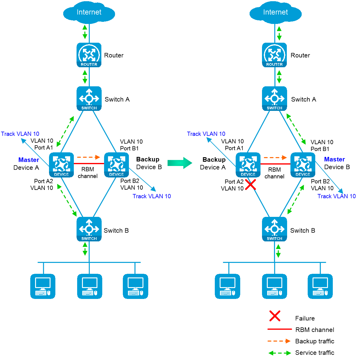
· As shown in Figure 5, when both Device A (active) and Device B (standby) are operating correctly, tracked VLAN 10 is in active state on Device A and in inactive state on Device B. As a result, Device A forwards all traffic that traverses the hot backup member devices.
· As shown in Figure 5, when downlink Port A2 of Device A fails, Device A and Device B switch their states. Then, VLAN 10 is placed in inactive state on Device A (standby) and in active state on Device B (active). As a result, Device B forwards all traffic that traverses the hot backup member devices.
Figure 5 Transparent in-path deployment of the hot backup member devices
Restrictions and guidelines
You can use hot backup only with VRRP master/backup mode. VRRP load sharing mode does not support hot backup.
You can configure hot backup to monitor track entries, VLANs, or interfaces, but you cannot configure VLAN monitoring in combination with track entry monitoring or interface monitoring. When you configure hot backup to monitor both track entries and interfaces, make sure the track entries are not associated with the monitored interfaces.
Configure hot backup
Prerequisites
Before you configure hot backup, verify that the following hardware and software settings are the same on the hot backup member devices:
· Device model.
· Software version.
· IRF member ID.
· Interface for setting up the control channel.
· Interface for setting up the data channel.
· Security zone configuration on the interfaces with the same interface number.
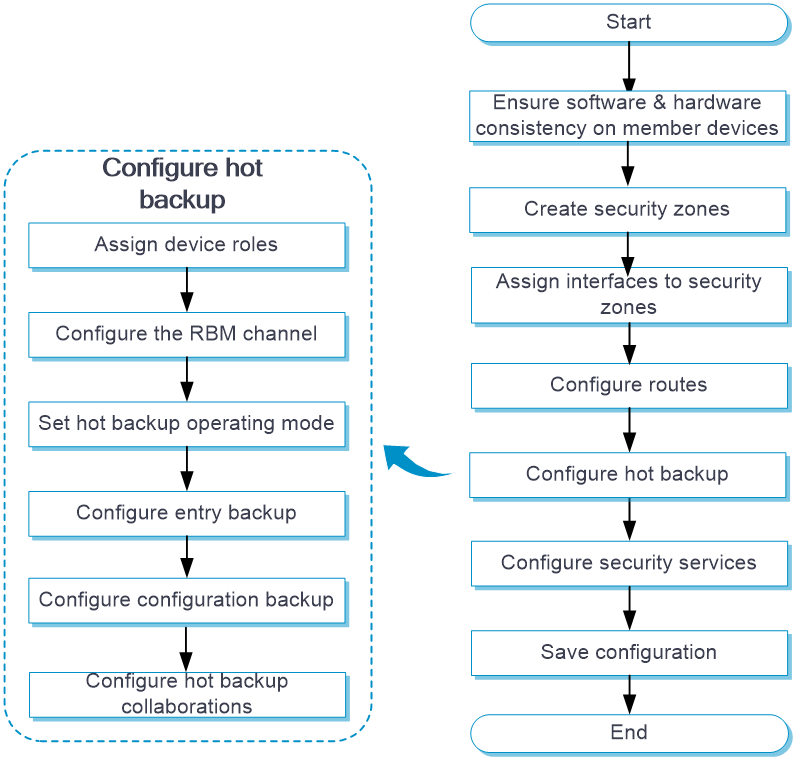
Hot backup configuration flow
Figure 6 Hot backup configuration flow chart
Configure hot backup
1. Click the System tab.
2. In the navigation pane, select High Availability > HA Group.
The HA Group page opens.
3. Click Configure.
The Configure Hot Backup page opens.
4. Configure hot backup. For more information about the related parameters, see Table 1.
|
Parameter |
Description |
|
Hot backup |
Set the status of the hot backup feature. |
|
RBM operating mode |
Set the hot backup operating mode. · Active/standby—The active device processes services, and the standby device stands by. · Dual-active—Both the hot backup member devices process services. |
|
Device role |
Assign roles to the hot backup member devices. |
|
Local IP |
Enter a local IP address to set up the control channel. The server end listens for TCP connection requests at this IP address. You can enter an IPv4 or IPv6 address, but not both. The local and peer IP addresses cannot be identical. |
|
Peer IP |
Enter the peer IP address used for setting up the control channel. You can enter an IPv4 or IPv6 address, but not both. The local and peer IP addresses cannot be identical. |
|
Peer port |
Enter the port number for the control channel. The hot backup member devices must have the same port number. |
|
Data channel |
Select an interface to set up the data channel which transmits backup packets and the packets that require transparent transmission. |
|
Keepalive interval |
Set the interval for the device to periodically send keepalive packets to the peer device. |
|
Max keepalive retries |
Set the maximum number of keepalive retries. If this limit is reached before the device receives any responses from the peer device, the device disconnects the RBM channels to the peer device. |
|
Fallback |
Enable this feature for traffic to be switched back to the original active device upon its recovery. |
|
Traffic reversion delay |
Set the delay that the primary and secondary devices must wait before a switchback. This delay allows the devices to finish service entry backup to prevent traffic loss. |
|
Back up sessions |
Set the status of session backup. If you enable this feature, the active device backs up service module entries to the standby device in real time. When the active device fails, the standby device can take over without service interruption. |
|
Back up HTTP Back up DNS |
Backs up the session entries created for received DNS and HTTP protocol packets. The hot backup member devices back up the sessions created for other application protocols as long as service entry backup is enabled. Enable HTTP and DNS backup if asymmetric-path traffic traverses the hot backup member devices. HTTP and DNS backup ensures that a flow and its return traffic are processed correctly on the hot backup member devices. If active/standby mode is used or only symmetric-path traffic traverses the hot backup member devices, disabling HTTP and DNS backup can improve performance of the hot backup member devices at the expense of delayed data synchronization. When you disable HTTP and DNS backup, make sure you are fully aware of the impact on the network. A device removes a DNS or HTTP connection if packet exchange is inactive. When a switchover interrupts a connection, the DNS or HTTP client re-initiates the connection immediately, which has little impact on user services. |
|
Back up AFT port blocks |
Backs up AFT port blocks in real time. |
|
Configuration consistency check |
Set the status of the configuration consistency check feature. |
|
Automatic configuration synchronization |
Set the status of the automatic configuration synchronization feature. After you enable this feature, the primary device backs up its configuration to the secondary device in bulk. When the configuration on the primary device changes, the primary device backs up the new configuration to the secondary device in real time. If the amount of configuration to be synchronized is large, bulk synchronization might take one to two hours. As a best practice to reduce the bulk synchronization duration, enable this feature when you configure hot backup. |
|
Role Switchover in Specific VRRP Groups |
Place the local device in backup state in a specified VRRP group for the peer device to become the master. Use this feature to redirect traffic from one member device to the other member device when traffic is unevenly distributed to the hot backup member devices operating in dual-active mode. This feature reduces the load on a device to balance load sharing and increase service processing efficiency. This feature takes effect only when both hot backup member devices are in active state. |
5. Configure Track settings. For more information about the related parameters, see Table 2.
|
Parameter |
Description |
|
Track entry association |
Select the track entries to be monitored by hot backup. If one of the monitored track entries becomes Negative, the hot backup member devices perform an active/standby switchover and switch traffic to the new active device to ensure service continuity. |
6. Click OK.
7. Click Check or Synchronize configuration to check configuration consistency or synchronize configuration on the HA Group page.
Table 3 Configuration consistency check and configuration synchronization parameters
|
Parameter |
Description |
|
Check |
Perform configuration consistency check manually. |
|
Synchronize configuration |
Manually synchronize the configuration of the primary device to the secondary device. |
8. Click Switch states on the HA Group page to switch the states of the hot backup member devices.
Table 4 State switchover parameters
|
Parameter |
Description |
|
Switch states |
Manually switch the states of the hot backup member devices. You can perform this task when the hardware of the active device requires replacement. Perform this task on the active and standby member devices operating in active/standby mode. Transient VRRP virtual IP conflicts might occur after you perform this task if VRRP is used with hot backup. The conflicts do not affect services. |
Configure VRRP collaboration
Associate hot backup with VRRP on the VRRP page. For more information about the configuration procedure, see VRRP help.
Configure hot backup to collaborate with a routing protocol
1. Click the System tab.
2. In the navigation pane, select High Availability > HA Group.
The HA Group page opens.
3. Click Configure.
The Configure Hot Backup page opens.
4. Configure routing collaboration parameters. For more information about the related parameters, see Table 5.
Table 5 Routing collaboration parameters
|
Parameter |
Description |
|
OSPF |
Adjust the link costs advertised by OSPF. |
|
IS-IS |
Adjust the link costs advertised by IS-IS. |
|
BGP |
Adjust the link costs advertised by BGP. |
|
OSPFv3 |
Adjust the link costs advertised by OSPFv3. |
|
Set absolute cost |
Enter an absolute link cost. The standby device will use this value to replace the link costs to be advertised. |
|
Set incremental cost |
Enter an incremental value. The standby device will add this value to the link costs to be advertised. |
5. Click OK.
Configure transparent in-path deployment
1. Click the System tab.
2. In the navigation pane, select High Availability > HA Group.
The HA Group page opens.
3. Click Configure.
The Configure Hot Backup page opens.
4. Configure monitoring parameters. For more information about the related parameters, see Table 6.
|
Parameter |
Description |
|
Interface |
Select the interfaces to be monitored by hot backup. You cannot configure hot backup to monitor aggregation member ports. The hot backup member devices monitor the status of the monitored interfaces to ensure interface status consistency. A monitored interface can forward traffic only when all monitored interfaces are up. |
|
VLAN |
Select the VLANs to be monitored by hot backup. The hot backup member devices monitor the member ports of a monitored VLAN to ensure member port status consistency. A port in a monitored VLAN can forward traffic only when all ports in the VLAN are up. You cannot configure hot backup to monitor VLAN 1. All access ports belong to VLAN 1 by default. If you configure hot backup to monitor VLAN 1, traffic forwarding will be affected on ports in use when an unused port is placed in down state in VLAN 1. |
5. Click OK.