- Table of Contents
-
- H3C Campus Fixed-Port Switches CLI-Based Quick Start Configuration Guide-6W101
- 01-H3C Devices CLI Reference
- 02-Login Management Quick Start Configuration Guide
- 03-Configuration File Management Quick Start Configruation Guide
- 04-Software Upgrade Quick Start Configuration Guide
- 05-Device Management Quick Start Configuration Guide
- 06-NTP Quick Start Configuration Guide
- 07-RBAC Quick Start Configuration Guide
- 08-IRF Quick Start Configuration Guide
- 09-Ethernet Interface Quick Start Configuration Guide
- 10-VLAN Quick Start Configuration Guide
- 11-Port Isolation Quick Start Configuration Guide
- 12-Loop Detection Quick Start Configuration Guide
- 13-QinQ Quick Start Configuration Guide
- 14-MAC Address Table Quick Start Configuration Guide
- 15-Ethernet Link Aggregation Quick Start Configuration Guide
- 16-Spanning Tree Quick Start Configuration Guide
- 17-DHCP Quick Start Configuration Guide
- 18-OSPF Quick Start Configuration Guide
- 19-Static Routing Quick Start Configuration Guide
- 20-Basic RIP Quick Start Configuration Guide
- 21-PBR Quick Start Configuration Guide
- 22-IGMP Snooping Quick Start Configuration Guide
- 23-Packet Filtering Quick Start Configuration Guide
- 24-QoS Quick Start Configuration Guide
- 25-IP Source Guard Quick Start Configuration Guide
- 26-SSH Quick Start Configuration Guide
- 27-Port Security Quick Start Configuration Guide
- 28-VRRP Quick Start Configuration Guide
- 29-PoE Quick Start Configuration Guide
- 30-Mirroring Quick Start Configuration Guide
- 31-Information Center Quick Start Configuration Guide
- 32-SNMP Quick Start Configuration Guide
- 33-LAN Networks Quick Start Configuration Guide
- Related Documents
-
| Title | Size | Download |
|---|---|---|
| 30-Mirroring Quick Start Configuration Guide | 638.90 KB |
Mirroring Quick Start Configuration Guide
Copyright © 2022 New H3C Technologies Co., Ltd. All rights reserved.
No part of this manual may be reproduced or transmitted in any form or by any means without prior written consent of New H3C Technologies Co., Ltd.
Except for the trademarks of New H3C Technologies Co., Ltd., any trademarks that may be mentioned in this document are the property of their respective owners.
The information in this document is subject to change without notice.
Contents
Configuring local port mirroring
Configuring local port mirroring with multiple monitor ports through a remote probe VLAN
Configuring Layer 2 remote port mirroring in egress port mode
Configuring Layer 2 remote port mirroring in reflector port mode
Configuring Layer 3 remote port mirroring in encapsulation parameter mode
Configuring local flow mirroring
Configuring local port mirroring
Introduction
The following information uses an example to describe the basic procedure for configuring local port mirroring.
Network configuration
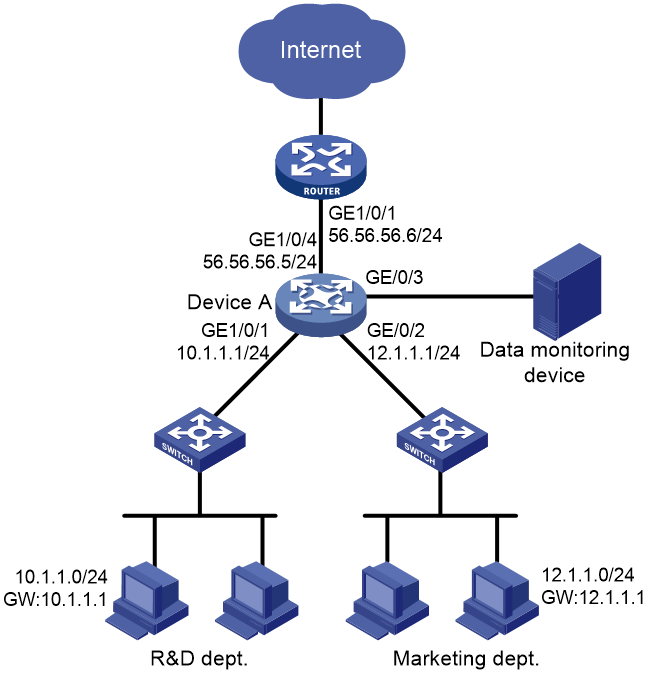
The departments of a company use IP addresses on different subnets. The R&D department uses subnet 10.1.1.0/24, and the marketing department uses subnet 12.1.1.0/24. Configure local port mirroring, so that the data monitoring device can monitor the traffic from the R&D department and marketing department to Internet and the traffic between the two departments.
Restrictions and guidelines
· For a local mirroring group to take effect, you must configure the mirroring source ports and monitor port for the group. Make sure the monitor port is not the member port of any other mirroring group.
· A monitor port can receive both mirrored packets copied from source ports and normally forwarded packets from other ports. Use a monitor port only for port mirroring, so the data monitoring device receives and analyzes only the mirrored traffic.
Procedure
# Assign IP address 10.1.1.1/24 to GigabitEthernet 1/0/1, which connects to the device of the R&D department.
<DeviceA> system-view
[DeviceA] interface gigabitethernet 1/0/1
[DeviceA-GigabitEthernet1/0/1] port link-mode route
[DeviceA-GigabitEthernet1/0/1] ip address 10.1.1.1 24
[DeviceA-GigabitEthernet1/0/1] quit
# Assign IP address 12.1.1.1/24 to GigabitEthernet 1/0/2, which connects to the device of the marketing department.
<DeviceA> system-view
[DeviceA] interface gigabitethernet 1/0/2
[DeviceA-GigabitEthernet1/0/2] port link-mode route
[DeviceA-GigabitEthernet1/0/2] ip address 12.1.1.1 24
[DeviceA-GigabitEthernet1/0/2] quit
# Assign IP address 56.56.56.5/24 to GigabitEthernet 1/0/4.
<DeviceA> system-view
[DeviceA] interface gigabitethernet 1/0/4
[DeviceA-GigabitEthernet1/0/4] port link-mode route
[DeviceA-GigabitEthernet1/0/4] ip address 56.56.56.5 24
[DeviceA-GigabitEthernet1/0/4] quit
# Create a local mirroring group.
[DeviceA] mirroring-group 1 local
# Configure the local mirroring group to mirror the incoming packets of interfaces GigabitEthernet 1/0/1 and GigabitEthernet 1/0/2.
[DeviceA] mirroring-group 1 mirroring-port gigabitethernet 1/0/1 gigabitethernet 1/0/2 inbound
# Configure interface GigabitEthernet 1/0/3 as the monitor port.
[DeviceA] mirroring-group 1 monitor-port gigabitethernet 1/0/3
# Disable the spanning tree protocol on the monitor port, GigabitEthernet 1/0/3.
[DeviceA] interface gigabitethernet 1/0/3
[DeviceA-GigabitEthernet1/0/3] undo stp enable
[DeviceA-GigabitEthernet1/0/3] quit
Verifying the configuration
# Display information about mirroring group 1 on Device A.
[DeviceA] display mirroring-group 1
Mirroring group 1:
Type: Local
Status: Active
Mirroring port:
GigabitEthernet1/0/1 Inbound
GigabitEthernet1/0/2 Inbound
Monitor port: GigabitEthernet1/0/3
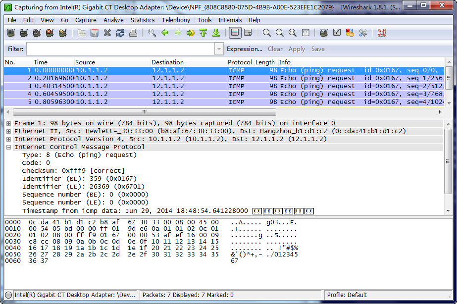
# Ping 56.56.56.6 from a host at 10.1.1.2 in the R&D department. Capture the packets on the data monitoring device, as shown in Figure 2. In this example, use Wireshark to capture packets.
Figure 2 Packets captured by Wireshark
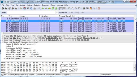
The captured packets show that the local port mirroring function takes effect. The data monitoring device can successfully monitor the specified traffic.
Configuration files
#
mirroring-group 1 local
#
interface GigabitEthernet1/0/1
port link-mode route
ip address 10.1.1.1 255.255.255.0
mirroring-group 1 mirroring-port inbound
#
interface GigabitEthernet1/0/2
port link-mode route
ip address 12.1.1.1 255.255.255.0
mirroring-group 1 mirroring-port inbound
#
interface GigabitEthernet1/0/3
port link-mode bridge
undo stp enable
mirroring-group 1 monitor-port
#
interface GigabitEthernet1/0/4
port link-mode route
ip address 56.56.56.5 255.255.255.0
#
Related documentation
· Port mirroring configuration in the network management and monitoring configuration guide for the device.
· Port mirroring commands in the network management and monitoring command reference for the device.
Configuring local port mirroring with multiple monitor ports through a remote probe VLAN
Introduction
The following information uses an example to describe the basic procedure for configuring local port mirroring with multiple monitor ports through the remote probe VLAN method.
Network configuration
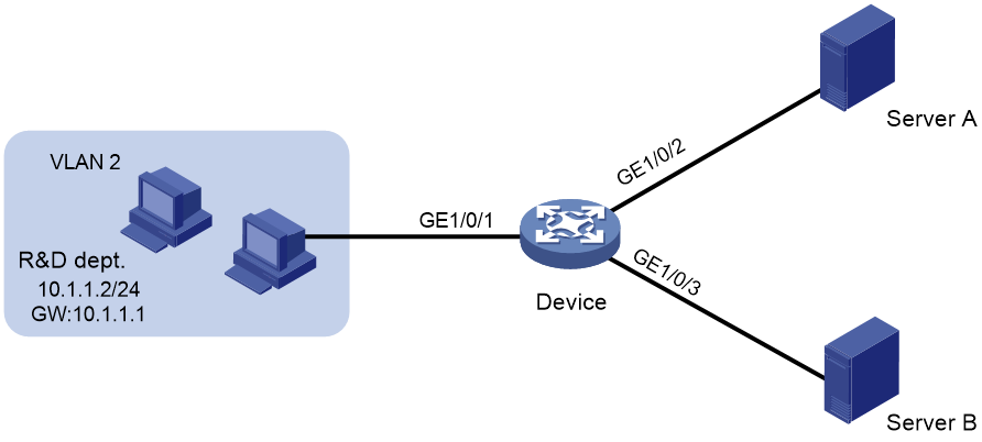
The R&D department connects to Device through interface GigabitEthernet 1/0/1. Configure mirroring, so that the data monitoring devices Server A and Server B can monitor the incoming and outgoing packets of the R&D department.
Figure 3 Network diagram
Restrictions and guidelines
When a VLAN is configured as a remote probe VLAN, use the VLAN for port mirroring exclusively.
Only a static VLAN that already exists can be configured as a remote probe VLAN. A VLAN can be configured as the remote probe VLAN for only one mirroring group.
To delete a VLAN that is configured as a remote probe VLAN, first remove the remote probe VLAN configuration.
Procedure
# Create VLAN 2.
<Device> system-view
[Device] vlan 2
[Device-vlan2] quit
# Create VLAN-interface 2, and assign an IP address to it.
[Device] interface vlan-interface 2
[Device-Vlan-interface2] ip address 10.1.1.1 24
[Device-Vlan-interface2] quit
# Create VLAN 10, which is to be used as the remote probe VLAN.
[Device] vlan 10
[Device-vlan10] quit
# Set the link type of GigabitEthernet 1/0/1 to trunk, and assign it to VLAN 2.
[Device] interface gigabitethernet 1/0/1
[Device-GigabitEthernet1/0/1] port link-type trunk
[Device-GigabitEthernet1/0/1] port trunk permit vlan 2
[Device-GigabitEthernet1/0/1] quit
# Create remote source group 1.
<Device> system-view
[Device] mirroring-group 1 remote-source
# Configure GigabitEthernet 1/0/1, which connects to the R&D department, as the source port of remote source group 1.
[Device] mirroring-group 1 mirroring-port gigabitethernet1/0/1 both
# Configure an unused port (GigabitEthernet 1/0/4 in this example) as the reflector port of mirroring group 1.
[Device] mirroring-group 1 reflector-port gigabitethernet1/0/4
This operation may delete all settings made on the interface. Continue? [Y/N]:y
# Assign the interfaces connecting to data monitoring devices to VLAN 10.
[Device] vlan 10
[Device-vlan10] port gigabitethernet1/0/2 to gigabitethernet1/0/3
[Device-vlan10] quit
# Configure VLAN 10 as the remote probe VLAN of mirroring group 1.
[Device] mirroring-group 1 remote-probe vlan 10
Verifying the configuration
# Display information about mirroring group 1 on Device.
[DeviceA] display mirroring-group all
Mirroring group 1:
Type: Remote source
Status: Active
Mirroring port:
GigabitEthernet1/0/1 Both
Reflector port: GigabitEthernet1/0/4
Remote probe VLAN: 10
Configuration files
#
mirroring-group 1 remote-source
mirroring-group 1 remote-probe vlan 10
#
vlan 2
#
vlan 10
#
interface Vlan-interface2
ip address 10.1.1.1 255.255.255.0
#
interface GigabitEthernet1/0/1
port link-mode bridge
port link-type trunk
port trunk permit vlan 2
mirroring-group 1 mirroring-port inbound
#
interface GigabitEthernet1/0/2
port link-mode bridge
port access vlan 10
#
interface GigabitEthernet1/0/3
port link-mode bridge
port access vlan 10
#
interface GigabitEthernet1/0/4
port link-mode bridge
port access vlan 10
mirroring-group 1 reflector-port
#
Related documentation
· Port mirroring configuration in the network management and monitoring configuration guide for the device.
· Port mirroring commands in the network management and monitoring command reference for the device.
Configuring Layer 2 remote port mirroring in egress port mode
Introduction
The following information uses an example to describe the basic procedure for configuring Layer 2 remote port mirroring in egress port mode.
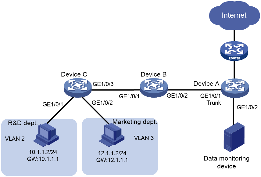
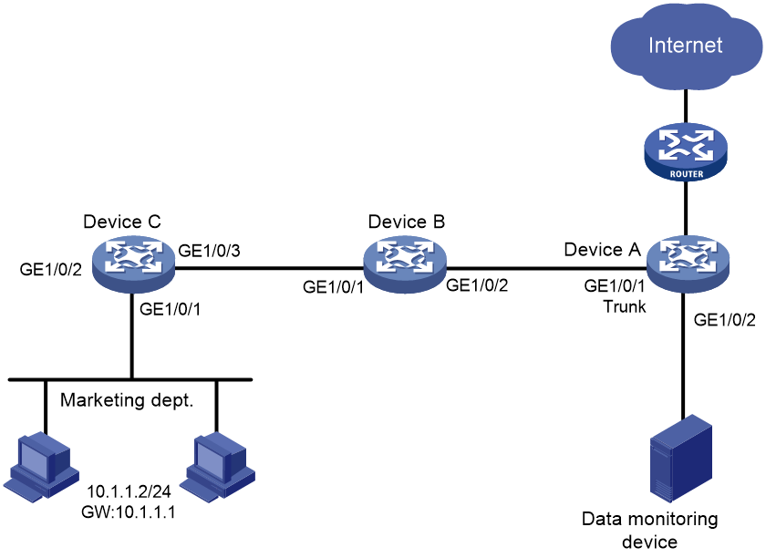
Network configuration
Restrictions and guidelines
To ensure correct forwarding of mirrored packets, assign the ports that connect intermediate devices to the source and destination devices to the remote probe VLAN.
As a best practice to ensure mirrored packet forwarding, configure mirroring on devices in the order of destination device, intermediate devices, and source device.
When configuring remote port mirroring on the destination device and source device, follow these restrictions and guidelines:
· When configuring a remote probe VLAN, follow these restrictions and guidelines:
¡ Make sure the VLAN is an existing static VLAN.
¡ Use the VLAN for remote port mirroring only.
¡ The VLAN can be used by only one remote source group.
· Make sure the remote mirroring groups on the source device and destination device use the same remote probe VLAN.
When configuring remote port mirroring on the destination device, follow these restrictions and guidelines:
· Make sure the monitor port is not the member port of any other mirroring group.
· Use the monitor port for port mirroring only.
When configuring remote port mirroring on the source device, follow these restrictions and guidelines:
· For mirroring to operate correctly, do not assign source ports to the remote probe VLAN.
· For mirroring to operate properly, do not configure any of the following features on the egress port:
¡ Spanning tree protocols.
¡ 802.1X.
¡ IGMP snooping.
¡ Static ARP.
¡ MAC address learning.
· Make sure the egress port is not the member port of any other mirroring group.
· A mirroring group supports only one egress port.
· When source ports are Layer 3 interfaces, you can implement Layer 2 remote mirroring only in egress port mode.
Procedures
Configuring Device A (destination device)
# Create VLANs 2 and 3.
<DeviceA> system-view
[DeviceA] vlan 2 to 3
# Create VLAN 5, which is to be used as the remote probe VLAN.
[DeviceA] vlan 5
[DeviceA-vlan5] quit
# Create VLAN-interface 2, and assign an IP address to it, which is to be used as the gateway for the VLAN. Configure VLAN-interface 3 in the same way.
[DeviceA] interface vlan-interface 2
[DeviceA-Vlan-interface2] ip address 10.1.1.1 24
[DeviceA-Vlan-interface2] quit
[DeviceA] interface vlan-interface 3
[DeviceA-Vlan-interface3] ip address 12.1.1.1 24
[DeviceA-Vlan-interface3] quit
# Set the link type of GigabitEthernet 1/0/1 to trunk, and assign it to VLANs 2, 3, and 5.
[DeviceA] interface gigabitethernet 1/0/1
[DeviceA-GigabitEthernet1/0/1] port link-type trunk
[DeviceA-GigabitEthernet1/0/1] port trunk permit vlan 2 3 5
[DeviceA-GigabitEthernet1/0/1] quit
# Create remote destination group 1.
[DeviceA] mirroring-group 1 remote-destination
# Configure VLAN 5 as the remote probe VLAN for the remote destination group. Configure GigabitEthernet 1/0/2, which connects to the data monitoring device, as the monitor port of remote destination group 1.
[DeviceA] mirroring-group 1 remote-probe vlan 5
[DeviceA] mirroring-group 1 monitor-port gigabitethernet 1/0/2
# Add the monitor port to the remote probe VLAN. When the mirrored packets are sent to the data monitoring device, they do not carry the tag of the remote probe VLAN. Therefore, set the link type of the interface to access.
[DeviceA] interface gigabitethernet 1/0/2
[DeviceA-GigabitEthernet1/0/2] port access vlan 5
# Disable the spanning tree protocol on the monitor port, GigabitEthernet 1/0/2.
[DeviceA-GigabitEthernet1/0/2] undo stp enable
[DeviceA-GigabitEthernet1/0/2] quit
Configuring Device B (intermediate device)
# Create VLANs 2 and 3.
<DeviceB> system-view
[DeviceB] vlan 2 to 3
# Create VLAN 5, which is to be used as the remote probe VLAN.
[DeviceB] vlan 5
[DeviceB-vlan5] quit
# Set the link type of GigabitEthernet 1/0/1 to trunk, and assign it to VLANs 2, 3, and 5.
[DeviceB] interface gigabitethernet 1/0/1
[DeviceB-GigabitEthernet1/0/1] port link-type trunk
[DeviceB-GigabitEthernet1/0/1] port trunk permit vlan 2 3 5
[DeviceB-GigabitEthernet1/0/1] quit
# Set the link type of GigabitEthernet 1/0/2 to trunk, and assign it to VLANs 2, 3, and 5.
[DeviceB] interface gigabitethernet 1/0/2
[DeviceB-GigabitEthernet1/0/2] port link-type trunk
[DeviceB-GigabitEthernet1/0/2] port trunk permit vlan 2 3 5
[DeviceB-GigabitEthernet1/0/2] quit
Configuring Device C (source device)
# Create VLANs 2 and 3.
<DeviceC> system-view
[DeviceC] vlan 2 to 3
# Assign GigabitEthernet 1/0/1 to VLAN 2.
[DeviceC] interface gigabitethernet 1/0/1
[DeviceC-GigabitEthernet1/0/1] port access vlan 2
[DeviceC-GigabitEthernet1/0/1] quit
# Assign GigabitEthernet 1/0/2 to VLAN 3.
[DeviceC] interface gigabitethernet 1/0/2
[DeviceC-GigabitEthernet1/0/2] port access vlan 3
[DeviceC-GigabitEthernet1/0/2] quit
# Create remote source group 1.
[DeviceC] mirroring-group 1 remote-source
# Create VLAN 5, which is to be used as the remote probe VLAN.
[DeviceC] vlan 5
[DeviceC-vlan5] quit
# Configure VLAN 5 as the remote probe VLAN, configure GigabitEthernet 1/0/1 as the source port, and configure GigabitEthernet 1/0/3 as the egress port for remote source group 1.
[DeviceC] mirroring-group 1 remote-probe vlan 5
[DeviceC] mirroring-group 1 mirroring-port gigabitethernet 1/0/1 inbound
[DeviceC] mirroring-group 1 monitor-egress gigabitethernet 1/0/3
# Set the link type of GigabitEthernet 1/0/3 to trunk, and assign it to VLANs 2, 3, and 5.
[DeviceC] interface gigabitethernet 1/0/3
[DeviceC-GigabitEthernet1/0/3] port link-type trunk
[DeviceC-GigabitEthernet1/0/3] port trunk permit vlan 2 3 5
[DeviceC-GigabitEthernet1/0/3] quit
# Disable the spanning tree protocol on the egress port, GigabitEthernet 1/0/3.
[DeviceC-GigabitEthernet1/0/3] undo stp enable
[DeviceC-GigabitEthernet1/0/3] quit
Verifying the configuration
# Display information about mirroring group 1 on Device C.
[DeviceC] display mirroring-group 1
Mirroring group 1:
Type: Remote source
Status: Active
Mirroring port:
GigabitEthernet1/0/1 Inbound
Monitor egress port: GigabitEthernet1/0/3
Remote probe VLAN: 5
# Display information about mirroring group 1 on Device A.
[DeviceA] display mirroring-group 1
Mirroring group 1:
Type: Remote destination
Status: Active
Monitor port: GigabitEthernet1/0/2
Remote probe VLAN: 5
# Ping a host at 12.1.1.2 in the marketing department from a host at 10.1.1.2 in the R&D department. Capture the packets on the data monitoring device, as shown in Figure 5. In this example, use Wireshark to capture packets.
Figure 5 Packets captured by Wireshark
The captured packets show that the Layer 2 remote port mirroring function takes effect. The data monitoring device can monitor the packets sent by the R&D department.
Configuration files
· Device A:
#
mirroring-group 1 remote-destination
mirroring-group 1 remote-probe vlan 5
#
vlan 2 to 3
#
vlan 5
#
interface Vlan-interface2
ip address 10.1.1.1 255.255.255.0
#
interface Vlan-interface3
ip address 12.1.1.1 255.255.255.0
#
interface GigabitEthernet1/0/1
port link-mode bridge
port link-type trunk
port trunk permit vlan 1 to 3 5
#
interface GigabitEthernet1/0/2
port link-mode bridge
port access vlan 5
undo stp enable
mirroring-group 1 monitor-port
#
· Device B:
#
vlan 2 to 3
#
vlan 5
#
interface GigabitEthernet1/0/1
port link-mode bridge
port link-type trunk
port trunk permit vlan 1 to 3 5
#
interface GigabitEthernet1/0/2
port link-mode bridge
port link-type trunk
port trunk permit vlan 1 to 3 5
#
· Device C:
#
mirroring-group 1 remote-source
mirroring-group 1 remote-probe vlan 5
#
vlan 2 to 3
#
vlan 5
#
interface GigabitEthernet1/0/1
port link-mode bridge
port access vlan 2
mirroring-group 1 mirroring-port inbound
#
interface GigabitEthernet1/0/2
port link-mode bridge
port access vlan 3
#
interface GigabitEthernet1/0/3
port link-mode bridge
port link-type trunk
port trunk permit vlan 1 to 3 5
mirroring-group 1 monitor-egress
#
Related documentation
· Port mirroring configuration in the network management and monitoring configuration guide for the device.
· Port mirroring commands in the network management and monitoring command reference for the device.
Configuring Layer 2 remote port mirroring in reflector port mode
Introduction
The following information uses an example to describe the basic procedure for configuring Layer 2 remote port mirroring in reflector port mode.
Network configuration
The marketing department of a company connects to the core device Device A through a Layer 2 network, and uses the subnet 10.1.1.0/24. Configure Layer 2 remote port mirroring in reflector port mode, so that the data monitoring device can monitor the traffic from the marketing department.
Figure 6 Network diagram
Restrictions and guidelines
To ensure correct forwarding of mirrored packets, assign the ports that connect intermediate devices to the source and destination devices to the remote probe VLAN.
As a best practice to ensure mirrored packet forwarding, configure mirroring on devices in the order of destination device, intermediate devices, and source device.
When configuring remote port mirroring on the destination device and source device, follow these restrictions and guidelines:
· When configuring a remote probe VLAN, follow these restrictions and guidelines:
¡ Make sure the VLAN is an existing static VLAN.
¡ Use the VLAN for remote port mirroring only.
¡ The VLAN can be used by only one remote source group.
· Make sure the remote mirroring groups on the source device and destination device use the same remote probe VLAN.
When configuring remote port mirroring on the destination device, follow these restrictions and guidelines:
· Make sure the monitor port is not the member port of any other mirroring group.
· Use the monitor port for port mirroring only.
When configuring remote port mirroring on the source device, follow these restrictions and guidelines:
· For mirroring to operate correctly, do not assign source ports to the remote probe VLAN.
· The port to be configured as a reflector port must be a port not in use. Do not connect a network cable to a reflector port.
· When a port is configured as a reflector port, the port restores to the factory default settings. You cannot configure other features on a reflector port.
· If an IRF port is bound to only one physical interface, do not configure the physical interface as a reflector port. If you do that, the IRF might split.
Procedures
Configuring Device A (destination device)
# Create VLAN 2.
<DeviceA> system-view
[DeviceA] vlan 2
# Create VLAN 5, which is to be used as the remote probe VLAN.
[DeviceA] vlan 5
[DeviceA-vlan5] quit
# Create VLAN-interface 2, and assign an IP address to it, which is to be used as the gateway for the VLAN.
[DeviceA] interface vlan-interface 2
[DeviceA-Vlan-interface2] ip address 10.1.1.1 24
[DeviceA-Vlan-interface2] quit
# Set the link type of GigabitEthernet 1/0/1 to trunk, and assign it to VLANs 2 and 5.
[DeviceA] interface gigabitethernet 1/0/1
[DeviceA-GigabitEthernet1/0/1] port link-type trunk
[DeviceA-GigabitEthernet1/0/1] port trunk permit vlan 2 5
[DeviceA-GigabitEthernet1/0/1] quit
# Create remote destination group 1.
[DeviceA] mirroring-group 1 remote-destination
# Configure VLAN 5 as the remote probe VLAN for the remote destination group. Configure GigabitEthernet 1/0/2, which connects to the data monitoring device, as the monitor port of remote destination group 1.
[DeviceA] mirroring-group 1 remote-probe vlan 5
[DeviceA] mirroring-group 1 monitor-port gigabitethernet 1/0/2
# Add the monitor port to the remote probe VLAN. When the mirrored packets are sent to the data monitoring device, they do not carry the tag of the remote probe VLAN. Therefore, set the link type of the interface to access.
[DeviceA] interface gigabitethernet 1/0/2
[DeviceA-GigabitEthernet1/0/2] port access vlan 5
# Disable the spanning tree protocol on the monitor port, GigabitEthernet 1/0/2.
[DeviceA-GigabitEthernet1/0/2] undo stp enable
[DeviceA-GigabitEthernet1/0/2] quit
Configuring Device B (intermediate device)
# Create VLAN 2.
<DeviceB> system-view
[DeviceB] vlan 2
# Create VLAN 5, which is to be used as the remote probe VLAN.
[DeviceB] vlan 5
[DeviceB-vlan5] quit
# Set the link type of GigabitEthernet 1/0/1 to trunk, and assign it to VLANs 2 and 5.
[DeviceB] interface gigabitethernet 1/0/1
[DeviceB-GigabitEthernet1/0/1] port link-type trunk
[DeviceB-GigabitEthernet1/0/1] port trunk permit vlan 2 5
[DeviceB-GigabitEthernet1/0/1] quit
# Set the link type of GigabitEthernet 1/0/2 to trunk, and assign it to VLANs 2 and 5.
[DeviceB] interface gigabitethernet 1/0/2
[DeviceB-GigabitEthernet1/0/2] port link-type trunk
[DeviceB-GigabitEthernet1/0/2] port trunk permit vlan 2 5
[DeviceB-GigabitEthernet1/0/2] quit
Configuring Device C (source device)
# Create VLAN 2.
<DeviceC> system-view
[DeviceC] vlan 2
# Assign GigabitEthernet 1/0/1 to VLAN 2.
[DeviceC] interface gigabitethernet 1/0/1
[DeviceC-GigabitEthernet1/0/1] port access vlan 2
[DeviceC-GigabitEthernet1/0/1] quit
# Create remote source group 1.
[DeviceC] mirroring-group 1 remote-source
# Create VLAN 5, which is to be used as the remote probe VLAN.
[DeviceC] vlan 5
[DeviceC-vlan5] quit
# Configure VLAN 5 as the remote probe VLAN, configure GigabitEthernet 1/0/1 as the source port, and configure GigabitEthernet 1/0/2 as the reflector port for remote source group 1.
[DeviceC] mirroring-group 1 remote-probe vlan 5
[DeviceC] mirroring-group 1 mirroring-port gigabitethernet 1/0/1 inbound
[DeviceC] mirroring-group 1 reflector-port gigabitethernet 1/0/2
# Set the link type of GigabitEthernet 1/0/3 to trunk, and assign it to VLANs 2 and 5.
[DeviceC] interface gigabitethernet 1/0/3
[DeviceC-GigabitEthernet1/0/3] port link-type trunk
[DeviceC-GigabitEthernet1/0/3] port trunk permit vlan 2
[DeviceC-GigabitEthernet1/0/3] quit
Verifying the configuration
# Display configuration information of all mirroring groups on Device A.
[DeviceA] display mirroring-group all
Mirroring group 1:
Type: Remote destination
Status: Active
Monitor port: GigabitEthernet1/0/2
Remote probe VLAN: 5
# Display configuration information of all mirroring groups on Device C.
[DeviceC] display mirroring-group all
Mirroring group 1:
Type: Remote source
Status: Active
Mirroring port:
GigabitEthernet1/0/1 inbound
Reflector port: GigabitEthernet1/0/2
Remote probe VLAN: 5
Configuration files
· Device A:
#
mirroring-group 1 remote-destination
mirroring-group 1 remote-probe vlan 5
#
vlan 2
#
vlan 5
#
interface Vlan-interface2
ip address 10.1.1.1 255.255.255.0
#
interface GigabitEthernet1/0/1
port link-mode bridge
port link-type trunk
port trunk permit vlan 1 to 2 5
#
interface GigabitEthernet1/0/2
port link-mode bridge
port access vlan 5
undo stp enable
mirroring-group 1 monitor-port
#
· Device B:
#
vlan 2
#
vlan 5
#
interface GigabitEthernet1/0/1
port link-mode bridge
port link-type trunk
port trunk permit vlan 1 to 2 5
#
interface GigabitEthernet1/0/2
port link-mode bridge
port link-type trunk
port trunk permit vlan 1 to 2 5
#
· Device C:
#
mirroring-group 1 remote-source
mirroring-group 1 remote-probe vlan 5
#
vlan 2
#
vlan 5
#
interface GigabitEthernet1/0/1
port link-mode bridge
port access vlan 2
mirroring-group 1 mirroring-port inbound
#
interface GigabitEthernet1/0/2
port link-mode bridge
mirroring-group 1 reflector-port
#
interface GigabitEthernet1/0/3
port link-mode bridge
port link-type trunk
port trunk permit vlan 2 5
#
Related documentation
· Port mirroring configuration in the network management and monitoring configuration guide for the device.
· Port mirroring commands in the network management and monitoring command reference for the device.
Configuring Layer 3 remote port mirroring in encapsulation parameter mode
Introduction
The following information uses an example to describe the basic procedure for configuring Layer 3 remote port mirroring in encapsulation parameter mode.
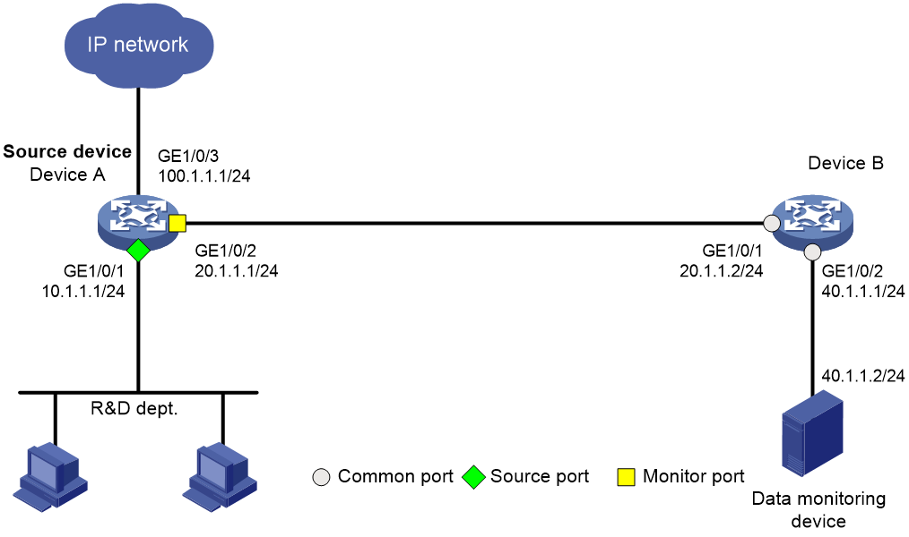
Network configuration
The R&D department uses the subnet 10.1.1.0/24. Configure Layer 3 remote port mirroring, so that the data monitoring device can monitor the traffic from the R&D department to Internet.
Restrictions and guidelines
If intermediate devices exist between the source device and the destination device, configure a unicast routing protocol on the intermediate devices to ensure that the source device and the destination device can reach each other at Layer 3.
Procedures
Configuring Device A
# Assign IP address 10.1.1.1 to interface GigabitEthernet 1/0/1.
<DeviceA> system-view
[DeviceA] interface gigabitethernet 1/0/1
[DeviceA-GigabitEthernet1/0/1] port link-mode route
[DeviceA-GigabitEthernet1/0/1] ip address 10.1.1.1 24
[DeviceA-GigabitEthernet1/0/1] quit
# Assign IP address 20.1.1.1 to interface GigabitEthernet 1/0/2.
[DeviceA] interface gigabitethernet 1/0/2
[DeviceA-GigabitEthernet1/0/2] port link-mode route
[DeviceA-GigabitEthernet1/0/2] ip address 20.1.1.1 24
[DeviceA-GigabitEthernet1/0/2] quit
# Assign IP address 100.1.1.1 to interface GigabitEthernet 1/0/3.
[DeviceA] interface gigabitethernet 1/0/3
[DeviceA-GigabitEthernet1/0/3] port link-mode route
[DeviceA-GigabitEthernet1/0/3] ip address 100.1.1.1 24
[DeviceA-GigabitEthernet1/0/3] quit
# Configure OSPF.
<DeviceB> system-view
[DeviceB] ospf 1
[DeviceB-ospf-1] area 0
[DeviceB-ospf-1-area-0.0.0.0] network 10.1.1.0 0.0.0.255
[DeviceB-ospf-1-area-0.0.0.0] network 20.1.1.0 0.0.0.255
[DeviceB-ospf-1-area-0.0.0.0] quit
[DeviceB-ospf-1] quit
# Create local mirroring group 1.
[DeviceA] mirroring-group 1 local
# Configure a source port for local mirroring group 1.
[DeviceA] mirroring-group 1 mirroring-port gigabitethernet 1/0/1 inbound
# Configure the monitor port and encapsulation parameters of mirrored packets for local mirroring group 1.
[DeviceA] mirroring-group 1 monitor-port gigabitethernet 1/0/2 destination-ip 40.1.1.2 source-ip 20.1.1.1
Configuring Device B
# Assign IP address 20.1.1.2 to interface GigabitEthernet 1/0/1.
<DeviceA> system-view
[DeviceA] interface gigabitethernet 1/0/1
[DeviceA-GigabitEthernet1/0/1] port link-mode route
[DeviceA-GigabitEthernet1/0/1] ip address 20.1.1.2 24
[DeviceA-GigabitEthernet1/0/1] quit
# Assign IP address 40.1.1.1 to interface GigabitEthernet 1/0/2.
[DeviceA] interface gigabitethernet 1/0/2
[DeviceA-GigabitEthernet1/0/2] port link-mode route
[DeviceA-GigabitEthernet1/0/2] ip address 40.1.1.1 24
[DeviceA-GigabitEthernet1/0/2] quit
# Configure OSPF.
<DeviceB> system-view
[DeviceB] ospf 1
[DeviceB-ospf-1] area 0
[DeviceB-ospf-1-area-0.0.0.0] network 20.1.1.0 0.0.0.255
[DeviceB-ospf-1-area-0.0.0.0] network 40.1.1.0 0.0.0.255
[DeviceB-ospf-1-area-0.0.0.0] quit
[DeviceB-ospf-1] quit
Verifying the configuration
# Display information about mirroring group 1 on Device A.
[DeviceA] display mirroring-group 1
Mirroring group 1:
Type: Local
Status: Active
Mirroring port:
GigabitEthernet1/0/1 Inbound
Monitor port: GigabitEthernet1/0/2
Encapsulation: Destination IP address 40.1.1.2
Source IP address 20.1.1.1
Destination MAC address 1025-4125-412b
Configuration files
· Device A:
#
ospf 1
area 0.0.0.0
network 10.1.1.0 0.0.0.255
network 20.1.1.0 0.0.0.255
#
interface GigabitEthernet1/0/1
port link-mode route
ip address 10.1.1.1 255.255.255.0
mirroring-group 1 mirroring-port inbound
#
interface GigabitEthernet1/0/2
port link-mode route
ip address 20.1.1.1 255.255.255.0
mirroring-group 1 monitor-port destination-ip 40.1.1.2 source-ip 20.1.1.1
#
interface GigabitEthernet1/0/3
port link-mode route
ip address 100.1.1.1 255.255.255.0
#
· Device B:
#
ospf 1
area 0.0.0.0
network 20.1.1.0 0.0.0.255
network 40.1.1.0 0.0.0.255
#
interface GigabitEthernet1/0/1
port link-mode route
ip address 20.1.1.2 255.255.255.0
#
interface GigabitEthernet1/0/2
port link-mode route
ip address 40.1.1.1 255.255.255.0
#
Related documentation
· Port mirroring configuration in the network management and monitoring configuration guide for the device.
· Port mirroring commands in the network management and monitoring command reference for the device.
Configuring local flow mirroring
Introduction
The following information uses an example to describe the basic procedure for configuring local flow mirroring.
Network configuration
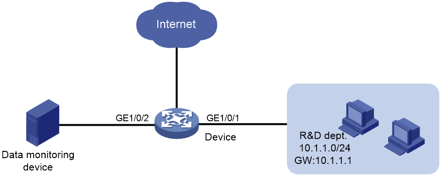
Procedure
# Assign IP address 10.1.1.1/24 to GigabitEthernet 1/0/1, which connects to the device of the R&D department.
<Device> system-view
[Device] interface gigabitethernet 1/0/1
[Device-GigabitEthernet1/0/1] port link-mode route
[Device-GigabitEthernet1/0/1] ip address 10.1.1.0 24
[Device-GigabitEthernet1/0/1] quit
# Create ACL 3000, and configure a rule to match the traffic from the R&D department to Internet.
[Device] acl number 3000
[Device-acl-adv-3000] rule permit tcp destination-port eq www source 10.1.1.0 0.0.0.255
[Device-acl-adv-3000] quit
# Create traffic class classifier_research, and use ACL 3000 as a match criterion.
[Device] traffic classifier classifier_research
[Device-classifier-classifier_research] if-match acl 3000
[Device-classifier-classifier_research] quit
# Create traffic behavior behavior_research, and configure an action of mirroring traffic to interface GigabitEthernet 1/0/2.
[Device] traffic behavior behavior_research
[Device-behavior-behavior_research] mirror-to interface gigabitethernet 1/0/2
[Device-behavior-behavior_research] quit
# Create QoS policy policy_research. Associate traffic class classifier_research with traffic behavior behavior_research.
[Device] qos policy policy_research
[Device-qospolicy-policy_research] classifier classifier_research behavior behavior_research
[Device-qospolicy-policy_research] quit
# Apply QoS policy policy_research to the inbound direction of interface GigabitEthernet 1/0/1.
[Device] interface gigabitethernet 1/0/1
[Device-GigabitEthernet1/0/1] qos apply policy policy_research inbound
[Device-GigabitEthernet1/0/1] quit
Verifying the configuration
# Display the flow mirroring configuration information on Device.
[Device] display qos policy interface
Interface: GigabitEthernet1/0/1
Direction: Inbound
Policy: policy_research
Classifier: classifier_research
Operator: AND
Rule(s) :
If-match acl 3000
Behavior: behavior_research
Mirroring:
Mirror to the interface: GigabitEthernet1/0/2
Configuration files
#
acl number 3000
rule 0 permit tcp source 10.1.1.0 0.0.0.255 destination-port eq www
#
traffic classifier classifier_research operator and
if-match acl 3000
#
traffic behavior behavior_research
mirror-to interface GigabitEthernet1/0/2
#
qos policy policy_research
classifier classifier_research behavior behavior_research
#
interface GigabitEthernet1/0/1
port link-mode route
ip address 10.1.1.0 0.0.0.255
qos apply policy policy_research inbound
#
Related documentation
· Flow mirroring configuration in the network management and monitoring configuration guide for the device.
· Flow mirroring commands in the network management and monitoring command reference for the device.