- Table of Contents
-
- H3C Campus Fixed-Port Switches CLI-Based Quick Start Configuration Guide-6W101
- 01-H3C Devices CLI Reference
- 02-Login Management Quick Start Configuration Guide
- 03-Configuration File Management Quick Start Configruation Guide
- 04-Software Upgrade Quick Start Configuration Guide
- 05-Device Management Quick Start Configuration Guide
- 06-NTP Quick Start Configuration Guide
- 07-RBAC Quick Start Configuration Guide
- 08-IRF Quick Start Configuration Guide
- 09-Ethernet Interface Quick Start Configuration Guide
- 10-VLAN Quick Start Configuration Guide
- 11-Port Isolation Quick Start Configuration Guide
- 12-Loop Detection Quick Start Configuration Guide
- 13-QinQ Quick Start Configuration Guide
- 14-MAC Address Table Quick Start Configuration Guide
- 15-Ethernet Link Aggregation Quick Start Configuration Guide
- 16-Spanning Tree Quick Start Configuration Guide
- 17-DHCP Quick Start Configuration Guide
- 18-OSPF Quick Start Configuration Guide
- 19-Static Routing Quick Start Configuration Guide
- 20-Basic RIP Quick Start Configuration Guide
- 21-PBR Quick Start Configuration Guide
- 22-IGMP Snooping Quick Start Configuration Guide
- 23-Packet Filtering Quick Start Configuration Guide
- 24-QoS Quick Start Configuration Guide
- 25-IP Source Guard Quick Start Configuration Guide
- 26-SSH Quick Start Configuration Guide
- 27-Port Security Quick Start Configuration Guide
- 28-VRRP Quick Start Configuration Guide
- 29-PoE Quick Start Configuration Guide
- 30-Mirroring Quick Start Configuration Guide
- 31-Information Center Quick Start Configuration Guide
- 32-SNMP Quick Start Configuration Guide
- 33-LAN Networks Quick Start Configuration Guide
- Related Documents
-
| Title | Size | Download |
|---|---|---|
| 21-PBR Quick Start Configuration Guide | 105.88 KB |
PBR Quick Start Configuration Guide
Copyright © 2022 New H3C Technologies Co., Ltd. All rights reserved.
No part of this manual may be reproduced or transmitted in any form or by any means without prior written consent of New H3C Technologies Co., Ltd.
Except for the trademarks of New H3C Technologies Co., Ltd., any trademarks that may be mentioned in this document are the property of their respective owners.
The information in this document is subject to change without notice.
Configuring source-IP-based interface PBR
Introduction
The following information uses an example to describe the basic procedure for configuring source-IP-based interface PBR.
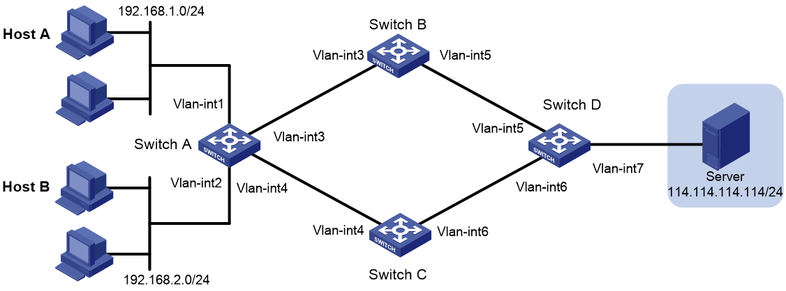
Network configuration
As shown in Figure 1, Configure static routes so that Switch A can forward all packets destined to the server (114.114.114.114/24) through Switch B.
Configure interface PBR to guide the forwarding of packets destined to the 114.114.114.114/24 received on VLAN-interface 2 of Switch A as follows:
· Set the next hop of packets sourced from 192.168.2.0/24 to Switch C.
· Set the next hop of other packets to Switch B.
|
Device |
Interface |
IP address |
Device |
Interface |
IP address |
|
Switch A |
Vlan-int1 |
192.168.1.1/24 |
Switch C: |
Vlan-int4 |
20.20.20.2/24 |
|
|
Vlan-int2 |
192.168.2.1/24 |
|
Vlan-int6 |
40.40.40.1/24 |
|
|
Vlan-int3 |
10.10.10.1/24 |
Switch D: |
Vlan-int5 |
30.30.30.2/24 |
|
|
Vlan-int4 |
20.20.20.1/24 |
|
Vlan-int6 |
40.40.40.2/24 |
|
Switch B: |
Vlan-int3 |
10.10.10.2/24 |
|
Vlan-int7 |
114.114.114.1/24 |
|
|
Vlan-int5 |
30.30.30.1/24 |
|
|
|
Procedure
Configuring Host A and Host B
# Configure IP address 192.168.1.2, subnet mask 255.255.255.0, and gateway address 192.168.1.1 for Host A. (Details not shown.)
# Configure IP address 192.168.2.2, subnet mask 255.255.255.0, and gateway address 192.168.2.1 for Host B. (Details not shown.)
Configuring Switch A
# Create VLANs and assign ports to them. Configure the IP address of each VLAN interface.
<SwitchA> system-view
[SwitchA] vlan 1
[SwitchA-vlan1] port gigabitethernet 1/0/1
[SwitchA-vlan1] quit
[SwitchA] vlan 2
[SwitchA-vlan2] port gigabitethernet 1/0/2
[SwitchA-vlan2] quit
[SwitchA] vlan 3
[SwitchA-vlan3] port gigabitethernet 1/0/3
[SwitchA-vlan3] quit
[SwitchA] vlan 4
[SwitchA-vlan4] port gigabitethernet 1/0/4
[SwitchA-vlan4] quit
[SwitchA] interface vlan-interface 1
[SwitchA-Vlan-interface1] ip address 192.168.1.1 24
[SwitchA-Vlan-interface1] quit
[SwitchA] interface vlan-interface 2
[SwitchA-Vlan-interface2] ip address 192.168.2.1 24
[SwitchA-Vlan-interface2] quit
[SwitchA] interface vlan-interface 3
[SwitchA-Vlan-interface3] ip address 10.10.10.1 24
[SwitchA-Vlan-interface3] quit
[SwitchA] interface vlan-interface 4
[SwitchA-Vlan-interface4] ip address 20.20.20.1 24
[SwitchA-Vlan-interface4] quit
# Configure a static route with destination address 114.114.114.114/24. Without PBR configured, all packets destined to 114.114.114.114/24 are forwarded through Switch B.
[SwitchA] ip route-static 114.114.114.114 24 10.10.10.2
# Configure ACL 3000 to match packets sourced from 192.168.2.0/24.
[SwitchA-acl-ipv4-adv-3000] rule permit ip source 192.168.2.0 0.0.0.255
[SwitchA-acl-ipv4-adv-3000] quit
# Configure ACL 3001 to match packets sourced from 192.168.2.0/24 and destined to 192.168.1.0/24.
[SwitchA] acl advanced 3001
[SwitchA-acl-ipv4-adv-3001] rule permit ip source 192.168.2.0 0.0.0.255 destination 192.168.1.0 0.0.0.255
[SwitchA-acl-ipv4-adv-3001] quit
# Configure Node 10 for the policy aaa and specify ACL 3001 for the policy node. Do not specify any apply clauses for the policy node to avoid interrupting traffic between different interfaces on Switch A. (Matching packets will be forwarded according to routing table lookup, and the next node will not be matched. This configuration ensures forwarding of packets between different subnets in the internal network without being processed by PBR. By default, the gateways on different subnets can access one another.
[SwitchA] policy-based-route aaa permit node 10
[SwitchA-pbr-aaa-10] if-match acl 3001
[SwitchA-pbr-aaa-10] quit
# Configure Node 20 for the policy aaa to forward packets matching ACL 3000 to next hop 20.20.20.2.
[SwitchA] policy-based-route aaa permit node 20
[SwitchA-pbr-aaa-20] if-match acl 3000
[SwitchA-pbr-aaa-20] apply next-hop 20.20.20.2
[SwitchA-pbr-aaa-20] quit
# Configure interface PBR by applying policy aaa to VLAN-interface 2.
[SwitchA] interface vlan-interface 2
[SwitchA-Vlan-interface2] ip policy-based-route aaa
[SwitchA-Vlan-interface2] quit
# Enable sending ICMP destination unreachable messages.
[SwitchA] ip unreachables enable
# Enable sending ICMP time exceeded messages.
[SwitchA] ip ttl-expires enable
# Save the configuration.
[SwitchA] save force
Configuring Switch B
# Create VLANs and assign ports to them. Configure the IP address of each VLAN interface.
<SwitchB> system-view
[SwitchB] vlan 3
[SwitchB-vlan3] port gigabitethernet 1/0/1
[SwitchB-vlan3] quit
[SwitchB] vlan 5
[SwitchB-vlan5] port gigabitethernet 1/0/2
[SwitchB-vlan5] quit
[SwitchB] interface vlan-interface 3
[SwitchB-Vlan-interface3] ip address 10.10.10.2 24
[SwitchB-Vlan-interface3] quit
[SwitchB] interface vlan-interface 5
[SwitchB-Vlan-interface5] ip address 30.30.30.1 24
[SwitchB-Vlan-interface5] quit
# Configure a static route with destination address 114.114.114.114/32.
[SwitchB] ip route-static 114.114.114.114 24 30.30.30.2
# Configure a static route with destination address 192.168.1.0/24.
[SwitchB] ip route-static 192.168.1.0 24 10.10.10.1
# Configure a static route with destination address 192.168.2.0/24.
[SwitchB] ip route-static 192.168.2.0 24 10.10.10.1
# Enable sending ICMP destination unreachable messages.
[SwitchB] ip unreachables enable
# Enable sending ICMP time exceeded messages.
[SwitchB] ip ttl-expires enable
# Save the configuration.
[SwitchB] save force
Configuring Switch C
# Create VLANs and assign ports to them. Configure the IP address of each VLAN interface.
<SwitchC> system-view
[SwitchC] vlan 4
[SwitchC-vlan4] port gigabitethernet 1/0/1
[SwitchC-vlan4] quit
[SwitchC] vlan 6
[SwitchC-vlan6] port gigabitethernet 1/0/2
[SwitchC-vlan6] quit
[SwitchC] interface vlan-interface 4
[SwitchC-Vlan-interface4] ip address 20.20.20.2 24
[SwitchC-Vlan-interface4] quit
[SwitchC] interface vlan-interface 6
[SwitchC-Vlan-interface6] ip address 40.40.40.1 24
[SwitchC-Vlan-interface6] quit
# Configure a static route with destination address 114.114.114.114/32.
[SwitchC] ip route-static 114.114.114.114 24 40.40.40.2
# Configure a static route with destination address 192.168.1.0/24.
[SwitchC] ip route-static 192.168.1.0 24 20.20.20.1
# Configure a static route with destination address 192.168.2.0/24.
[SwitchC] ip route-static 192.168.2.0 24 20.20.20.1
# Enable sending ICMP destination unreachable messages.
[SwitchC] ip unreachables enable
# Enable sending ICMP time exceeded messages.
[SwitchC] ip ttl-expires enable
# Save the configuration.
[SwitchC] save force
Configuring Switch D
# Create VLANs and assign ports to them. Configure the IP address of each VLAN interface.
<SwitchD> system-view
[SwitchD] vlan 5
[SwitchD-vlan5] port gigabitethernet 1/0/1
[SwitchD-vlan5] quit
[SwitchD] vlan 6
[SwitchD-vlan6] port gigabitethernet 1/0/2
[SwitchD-vlan6] quit
[SwitchD] vlan 7
[SwitchD-vlan7] port gigabitethernet 1/0/3
[SwitchD-vlan7] quit
[SwitchD] interface vlan-interface 5
[SwitchD-Vlan-interface5] ip address 30.30.30.2 24
[SwitchD-Vlan-interface5] quit
[SwitchD] interface vlan-interface 6
[SwitchD-Vlan-interface6] ip address 40.40.40.2 24
[SwitchD-Vlan-interface6] quit
[SwitchD] interface vlan-interface 7
[SwitchD-Vlan-interface7] ip address 114.114.114.1 24
[SwitchD-Vlan-interface7] quit
# Configure a static route with destination address 192.168.1.0/24.
[SwitchD] ip route-static 192.168.1.0 24 30.30.30.1
# Configure a static route with destination address 192.168.2.0/24.
[SwitchD] ip route-static 192.168.2.0 24 40.40.40.1
# Enable sending ICMP destination unreachable messages.
[SwitchD] ip unreachables enable
# Enable sending ICMP time exceeded messages.
[SwitchD] ip ttl-expires enable
# Save the configuration.
[SwitchD] save force
Verifying the configuration
# Execute the display ip policy-based-route command on Switch A to verify that interface PBR is successfully configured.
[SwitchA] display ip policy-based-route interface Vlan-interface 2
Policy-based routing information for interface Vlan-interface2:
Policy name: aaa
node 10 permit:
if-match acl 3001
Matches: 0, bytes: 0
node 20 permit:
if-match acl 3000
apply next-hop 20.20.20.2
Matches: 0, bytes: 0
Total matches: 0, total bytes: 0
# Use the tracert command to identify the path from Host A to the server 114.114.114.114/24. (To use the tracert function, enable sending ICMP time exceeded messages on intermediate devices, and enable sending ICMP destination unreachable messages on the destination device.) You can see that the packets are forwarded through Switch B.
C:\Documents and Settings\Administrator>tracert 114.114.114.114
Tracing route to 114.114.114.114 over a maximum of 30 hops
1 <1 ms <1 ms <1 ms 192.168.1.1
2 <1 ms <1 ms <1 ms 10.10.10.2
3 <1 ms <1 ms <1 ms 30.30.30.2
4 1 ms <1 ms <1 ms 114.114.114.114
Trace complete.
# Use the tracert command to identify the path from Host B to the server 114.114.114.114/24. You can see that the packets are forwarded through Switch C. The PBR configuration has taken effect.
C:\Documents and Settings\Administrator>tracert 114.114.114.114
Tracing route to 114.114.114.114 over a maximum of 30 hops
1 <1 ms <1 ms <1 ms 192.168.2.1
2 <1 ms <1 ms <1 ms 20.20.20.2
3 <1 ms <1 ms <1 ms 40.40.40.2
4 1 ms <1 ms <1 ms 114.114.114.114
Trace complete.
Configuration files
· Switch A:
#
ip unreachables enable
ip ttl-expires enable
#
vlan 1
#
vlan 2 to 4
#
policy-based-route aaa permit node 10
if-match acl 3001
#
policy-based-route aaa permit node 20
if-match acl 3000
apply next-hop 20.20.20.2
#
interface Vlan-interface1
ip address 192.168.1.1 255.255.255.0
#
interface Vlan-interface2
ip address 192.168.2.1 255.255.255.0
ip policy-based-route aaa
#
interface Vlan-interface3
ip address 10.10.10.1 255.255.255.0
#
interface Vlan-interface4
ip address 20.20.20.1 255.255.255.0
#
interface GigabitEthernet1/0/1
port link-mode bridge
#
interface GigabitEthernet1/0/2
port link-mode bridge
port access vlan 2
#
interface GigabitEthernet1/0/3
port link-mode bridge
port access vlan 3
#
interface GigabitEthernet1/0/4
port link-mode bridge
port access vlan 4
#
ip route-static 114.114.114.114 24 10.10.10.2
#
acl advanced 3000
rule 0 permit ip source 192.168.2.0 0.0.0.255
#
acl advanced 3001
rule 0 permit ip source 192.168.2.0 0.0.0.255 destination 192.168.1.0 0.0.0.255
#
· Switch B:
#
ip unreachables enable
ip ttl-expires enable
#
vlan 3
#
vlan 5
#
interface Vlan-interface3
ip address 10.10.10.2 255.255.255.0
#
interface Vlan-interface5
ip address 30.30.30.1 255.255.255.0
#
interface GigabitEthernet1/0/1
port link-mode bridge
port access vlan 3
#
interface GigabitEthernet1/0/2
port link-mode bridge
port access vlan 5
#
ip route-static 114.114.114.114 24 30.30.30.2
ip route-static 192.168.1.0 24 10.10.10.1
ip route-static 192.168.2.0 24 10.10.10.1
#
· Switch C:
#
ip unreachables enable
ip ttl-expires enable
#
vlan 4
#
vlan 6
#
interface Vlan-interface4
ip address 20.20.20.2 255.255.255.0
#
interface Vlan-interface6
ip address 40.40.40.1 255.255.255.0
#
interface GigabitEthernet1/0/1
port link-mode bridge
port access vlan 4
#
interface GigabitEthernet1/0/2
port link-mode bridge
port access vlan 6
#
ip route-static 114.114.114.114 24 40.40.40.2
ip route-static 192.168.1.0 24 20.20.20.1
ip route-static 192.168.2.0 24 20.20.20.1
#
· Switch D:
#
ip unreachables enable
ip ttl-expires enable
#
vlan 5 to 7
#
interface Vlan-interface5
ip address 30.30.30.2 255.255.255.0
#
interface Vlan-interface6
ip address 40.40.40.2 255.255.255.0
#
interface Vlan-interface7
ip address 114.114.114.1 255.255.255.0
#
interface GigabitEthernet1/0/1
port link-mode bridge
port access vlan 5
#
interface GigabitEthernet1/0/2
port link-mode bridge
port access vlan 6
#
interface GigabitEthernet1/0/3
port link-mode bridge
port access vlan 7
#
ip route-static 192.168.1.0 24 30.30.30.1
ip route-static 192.168.2.0 24 40.40.40.1
#
Related documentation
· Policy-based routing configuration in the Layer 3—IP routing configuration guide for the device.
· Policy-based routing commands in the Layer 3—IP routing command reference for the device.