- Table of Contents
-
- H3C Campus Fixed-Port Switches CLI-Based Quick Start Configuration Guide-6W101
- 01-H3C Devices CLI Reference
- 02-Login Management Quick Start Configuration Guide
- 03-Configuration File Management Quick Start Configruation Guide
- 04-Software Upgrade Quick Start Configuration Guide
- 05-Device Management Quick Start Configuration Guide
- 06-NTP Quick Start Configuration Guide
- 07-RBAC Quick Start Configuration Guide
- 08-IRF Quick Start Configuration Guide
- 09-Ethernet Interface Quick Start Configuration Guide
- 10-VLAN Quick Start Configuration Guide
- 11-Port Isolation Quick Start Configuration Guide
- 12-Loop Detection Quick Start Configuration Guide
- 13-QinQ Quick Start Configuration Guide
- 14-MAC Address Table Quick Start Configuration Guide
- 15-Ethernet Link Aggregation Quick Start Configuration Guide
- 16-Spanning Tree Quick Start Configuration Guide
- 17-DHCP Quick Start Configuration Guide
- 18-OSPF Quick Start Configuration Guide
- 19-Static Routing Quick Start Configuration Guide
- 20-Basic RIP Quick Start Configuration Guide
- 21-PBR Quick Start Configuration Guide
- 22-IGMP Snooping Quick Start Configuration Guide
- 23-Packet Filtering Quick Start Configuration Guide
- 24-QoS Quick Start Configuration Guide
- 25-IP Source Guard Quick Start Configuration Guide
- 26-SSH Quick Start Configuration Guide
- 27-Port Security Quick Start Configuration Guide
- 28-VRRP Quick Start Configuration Guide
- 29-PoE Quick Start Configuration Guide
- 30-Mirroring Quick Start Configuration Guide
- 31-Information Center Quick Start Configuration Guide
- 32-SNMP Quick Start Configuration Guide
- 33-LAN Networks Quick Start Configuration Guide
- Related Documents
-
| Title | Size | Download |
|---|---|---|
| 19-Static Routing Quick Start Configuration Guide | 328.51 KB |
Static Routing Quick Start Configuration Guide
Copyright © 2022 New H3C Technologies Co., Ltd. All rights reserved.
No part of this manual may be reproduced or transmitted in any form or by any means without prior written consent of New H3C Technologies Co., Ltd.
Except for the trademarks of New H3C Technologies Co., Ltd., any trademarks that may be mentioned in this document are the property of their respective owners.
The information in this document is subject to change without notice.
Contents
Configuring static routing-Track-NQA collaboration
Accessing the Web interface of a device in a different subnet
Configuring basic IPv6 static route settings
Configuring basic static route settings
Configuring a floating static route
Configuring static routing-Track-NQA collaboration
Introduction
The following information uses an example to describe the basic procedure for configuring static routing-Track-NQA collaboration.
Network configuration
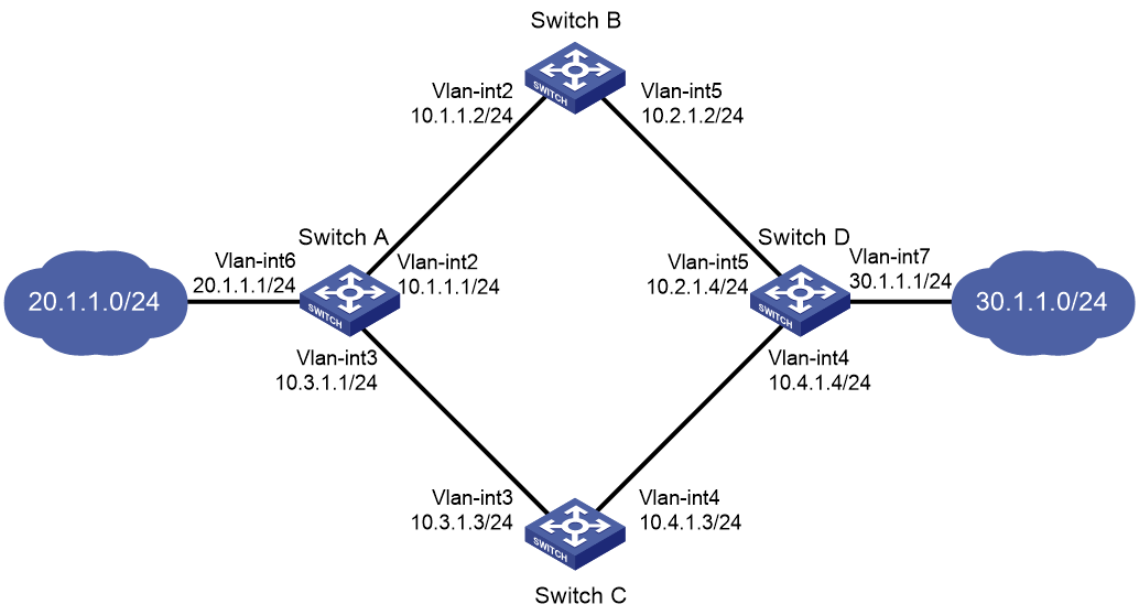
As shown in Figure 1:
· Switch A is the default gateway of the hosts in network 20.1.1.0/24.
· Switch D is the default gateway of the hosts in network 30.1.1.0/24.
· Hosts in the two networks communicate with each other through static routes.
To ensure network availability, configure route backup and static routing-Track-NQA collaboration on Switch A and Switch D as follows:
· On Switch A, assign a higher priority to the static route to 30.1.1.0/24 with next hop Switch B. This route is the master route. The static route to 30.1.1.0/24 with next hop Switch C acts as the backup route. When the master route is unavailable, the backup route takes effect. Switch A forwards packets to 30.1.1.0/24 through Switch C.
· On Switch D, assign a higher priority to the static route to 20.1.1.0/24 with next hop Switch B. This route is the master route. The static route to 20.1.1.0/24 with next hop Switch C acts as the backup route. When the master route is unavailable, the backup route takes effect. Switch D forwards packets to 20.1.1.0/24 through Switch C.
Analysis
1. Assign IP address to the devices.
2. Configure static routes:
Assign a higher priority to the static route with Switch B as the next hop (master route) than the static route with Switch C as the next hop (backup route).
3. Configure NQA operations:
Configure NQA operations on Switch A and Switch D to test the connectivity of the path Switch A-Switch B-Switch D. Associate Track with the NQA operations to implement collaboration between static routing, Track, and NQA.
Procedure
Configuring Switch A
# Create VLANs and assign ports to them. Configure the IP address of each VLAN interface.
<SwitchA> system-view
[SwitchA] vlan 2
[SwitchA-vlan2] port gigabitethernet 1/0/1
[SwitchA-vlan2] quit
[SwitchA] vlan 3
[SwitchA-vlan3] port gigabitethernet 1/0/2
[SwitchA-vlan3] quit
[SwitchA] vlan 6
[SwitchA-vlan6] port gigabitethernet 1/0/3
[SwitchA-vlan6] quit
[SwitchA] interface vlan-interface 2
[SwitchA-Vlan-interface2] ip address 10.1.1.1 24
[SwitchA-Vlan-interface2] quit
[SwitchA] interface vlan-interface 3
[SwitchA-Vlan-interface3] ip address 10.3.1.1 24
[SwitchA-Vlan-interface3] quit
[SwitchA] interface vlan-interface 6
[SwitchA-Vlan-interface6] ip address 20.1.1.1 24
[SwitchA-Vlan-interface6] quit
# Configure a static route to 30.1.1.0/24 with next hop 10.1.1.2 and the default priority (60). Associate this static route with track entry 1.
[SwitchA] ip route-static 30.1.1.0 24 10.1.1.2 track 1
# Configure a static route to 30.1.1.0/24 with next hop 10.3.1.3 and priority 80.
[SwitchA] ip route-static 30.1.1.0 24 10.3.1.3 preference 80
# Configure a static route to 10.2.1.4 with next hop 10.1.1.2.
[SwitchA] ip route-static 10.2.1.4 24 10.1.1.2
# Create an NQA operation with administrator name admin and operation tag test.
[SwitchA] nqa entry admin test
# Specify the ICMP echo operation type.
[SwitchA-nqa-admin-test] type icmp-echo
# Specify 10.2.1.4 as the destination address of the operation and specify 10.1.1.2 as the next hop of the operation to detect connectivity of the path Switch A-Switch B-Switch D.
[SwitchA-nqa-admin-test-icmp-echo] destination ip 10.2.1.4
[SwitchA-nqa-admin-test-icmp-echo] next-hop ip 10.1.1.2
# Configure the ICMP echo operation to repeat every 100 milliseconds.
[SwitchA-nqa-admin-test-icmp-echo] frequency 100
# Configure reaction entry 1, specifying that five consecutive probe failures trigger the Track module.
[SwitchA-nqa-admin-test-icmp-echo] reaction 1 checked-element probe-fail threshold-type consecutive 5 action-type trigger-only
[SwitchA-nqa-admin-test-icmp-echo] quit
# Start the NQA operation.
[SwitchA] nqa schedule admin test start-time now lifetime forever
# Configure track entry 1, and associate it with reaction entry 1 of the NQA operation.
[SwitchA] track 1 nqa entry admin test reaction 1
[SwitchA-track-1] quit
# Save the configuration.
[SwitchA] save force
Configuring Switch B
# Create VLANs and assign ports to them. Configure the IP address of each VLAN interface.
<SwitchB> system-view
[SwitchB] vlan 2
[SwitchB-vlan2] port gigabitethernet 1/0/1
[SwitchB-vlan2] quit
[SwitchB] vlan 5
[SwitchB-vlan5] port gigabitethernet 1/0/2
[SwitchB-vlan5] quit
[SwitchB] interface vlan-interface 2
[SwitchB-Vlan-interface2] ip address 10.1.1.2 24
[SwitchB-Vlan-interface2] quit
[SwitchB] interface vlan-interface 5
[SwitchB-Vlan-interface5] ip address 10.2.1.2 24
[SwitchB-Vlan-interface5] quit
# Configure a static route to 30.1.1.0/24 with next hop 10.2.1.4.
[SwitchB] ip route-static 30.1.1.0 24 10.2.1.4
# Configure a static route to 20.1.1.0/24 with next hop 10.1.1.1.
[SwitchB] ip route-static 20.1.1.0 24 10.1.1.1
# Save the configuration.
[SwitchB] save force
Configuring Switch C
# Create VLANs and assign ports to them. Configure the IP address of each VLAN interface.
<SwitchC> system-view
[SwitchC] vlan 3
[SwitchC-vlan3] port gigabitethernet 1/0/1
[SwitchC-vlan3] quit
[SwitchC] vlan 4
[SwitchC-vlan4] port gigabitethernet 1/0/2
[SwitchC-vlan4] quit
[SwitchC] interface vlan-interface 3
[SwitchC-Vlan-interface3] ip address 10.3.1.3 24
[SwitchC-Vlan-interface3] quit
[SwitchC] interface vlan-interface 4
[SwitchC-Vlan-interface4] ip address 10.4.1.3 24
[SwitchC-Vlan-interface4] quit
# Configure a static route to 30.1.1.0/24 with next hop 10.4.1.4.
[SwitchC] ip route-static 30.1.1.0 24 10.4.1.4
# Configure a static route to 20.1.1.0/24 with next hop 10.3.1.1.
[SwitchC] ip route-static 20.1.1.0 24 10.3.1.1
# Save the configuration.
[SwitchC] save force
Configuring Switch D
# Create VLANs and assign ports to them. Configure the IP address of each VLAN interface.
<SwitchD> system-view
[SwitchD] vlan 4
[SwitchD-vlan4] port gigabitethernet 1/0/1
[SwitchD-vlan4] quit
[SwitchD] vlan 5
[SwitchD-vlan5] port gigabitethernet 1/0/2
[SwitchD-vlan5] quit
[SwitchD] vlan 7
[SwitchD-vlan7] port gigabitethernet 1/0/3
[SwitchD-vlan7] quit
[SwitchD] interface vlan-interface 4
[SwitchD-Vlan-interface6] ip address 10.4.1.4 24
[SwitchD-Vlan-interface6] quit
[SwitchD] interface vlan-interface 5
[SwitchD-Vlan-interface5] ip address 10.2.1.4 24
[SwitchD-Vlan-interface5] quit
[SwitchD] interface vlan-interface 7
[SwitchD-Vlan-interface7] ip address 30.1.1.1 24
[SwitchD-Vlan-interface7] quit
# Configure a static route to 20.1.1.0/24 with next hop 10.2.1.2 and the default priority (60). Associate this static route with track entry 1.
[SwitchD] ip route-static 20.1.1.0 24 10.2.1.2 track 1
# Configure a static route to 20.1.1.0/24 with next hop 10.4.1.3 and priority 80.
[SwitchD] ip route-static 20.1.1.0 24 10.4.1.3 preference 80
# Configure a static route to 10.1.1.1 with next hop 10.2.1.2.
[SwitchD] ip route-static 10.1.1.1 24 10.2.1.2
# Create an NQA operation with administrator name admin and operation tag test.
[SwitchD] nqa entry admin test
# Specify the ICMP echo operation type.
[SwitchD-nqa-admin-test] type icmp-echo
# Specify 10.1.1.1 as the destination address of the operation and specify 10.2.1.2 as the next hop of the operation to detect connectivity of the path Switch D-Switch B-Switch A.
[SwitchD-nqa-admin-test-icmp-echo] destination ip 10.1.1.1
[SwitchD-nqa-admin-test-icmp-echo] next-hop ip 10.2.1.2
# Configure the ICMP echo operation to repeat every 100 milliseconds.
[SwitchD-nqa-admin-test-icmp-echo] frequency 100
# Configure reaction entry 1, specifying that five consecutive probe failures trigger the Track module.
[SwitchD-nqa-admin-test-icmp-echo] reaction 1 checked-element probe-fail threshold-type consecutive 5 action-type trigger-only
[SwitchD-nqa-admin-test-icmp-echo] quit
# Start the NQA operation.
[SwitchD] nqa schedule admin test start-time now lifetime forever
# Configure track entry 1, and associate it with reaction entry 1 of the NQA operation.
[SwitchD] track 1 nqa entry admin test reaction 1
[SwitchD-track-1] quit
# Save the configuration.
[SwitchD] save force
Verifying the configuration
# Display track entry information on Switch A.
[SwitchA] display track all
Track ID: 1
State: Positive
Duration: 0 days 0 hours 0 minutes 32 seconds
Tracked object type: NQA
Notification delay: Positive 0, Negative 0 (in seconds)
Tracked object:
NQA entry: admin test
Reaction: 1
Remote IP/URL: 10.2.1.4
Local IP: --
Interface: --
# Display the routing table of Switch A.
[SwitchA] display ip routing-table
Destinations : 10 Routes : 10
Destination/Mask Proto Pre Cost NextHop Interface
10.1.1.0/24 Direct 0 0 10.1.1.1 Vlan2
10.1.1.1/32 Direct 0 0 127.0.0.1 InLoop0
10.2.1.0/24 Static 60 0 10.1.1.2 Vlan2
10.3.1.0/24 Direct 0 0 10.3.1.1 Vlan3
10.3.1.1/32 Direct 0 0 127.0.0.1 InLoop0
20.1.1.0/24 Direct 0 0 20.1.1.1 Vlan6
20.1.1.1/32 Direct 0 0 127.0.0.1 InLoop0
30.1.1.0/24 Static 60 0 10.1.1.2 Vlan2
127.0.0.0/8 Direct 0 0 127.0.0.1 InLoop0
127.0.0.1/32 Direct 0 0 127.0.0.1 InLoop0
The output shows that the status of the track entry is Positive, indicating that the NQA operation has succeeded and the master route is available. Switch A forwards packets to 30.1.1.0/24 through Switch B.
# Remove the IP address of interface VLAN-interface 2 on Switch B.
<SwitchB> system-view
[SwitchB] interface vlan-interface 2
[SwitchB-Vlan-interface2] undo ip address
# Display track entry information on Switch A.
[SwitchA] display track all
Track ID: 1
State: Negative
Duration: 0 days 0 hours 0 minutes 32 seconds
Tracked object type: NQA
Notification delay: Positive 0, Negative 0 (in seconds)
Tracked object:
NQA entry: admin test
Reaction: 1
Remote IP/URL: 10.2.1.4
Local IP: --
Interface: --
# Display the routing table of Switch A.
[SwitchA] display ip routing-table
Destinations : 10 Routes : 10
Destination/Mask Proto Pre Cost NextHop Interface
10.1.1.0/24 Direct 0 0 10.1.1.1 Vlan2
10.1.1.1/32 Direct 0 0 127.0.0.1 InLoop0
10.2.1.0/24 Static 60 0 10.1.1.2 Vlan2
10.3.1.0/24 Direct 0 0 10.3.1.1 Vlan3
10.3.1.1/32 Direct 0 0 127.0.0.1 InLoop0
20.1.1.0/24 Direct 0 0 20.1.1.1 Vlan6
20.1.1.1/32 Direct 0 0 127.0.0.1 InLoop0
30.1.1.0/24 Static 80 0 10.3.1.3 Vlan3
127.0.0.0/8 Direct 0 0 127.0.0.1 InLoop0
127.0.0.1/32 Direct 0 0 127.0.0.1 InLoop0
The output shows that the status of the track entry is Negative, indicating that the NQA operation has failed and the master route is unavailable. Switch A forwards packets to 30.1.1.0/24 through Switch C. The backup static route has taken effect.
# Verify that hosts in 20.1.1.0/24 can communicate with the hosts in 30.1.1.0/24 when the master route fails.
[SwitchA] ping -a 20.1.1.1 30.1.1.1
Ping 30.1.1.1: 56 data bytes, press CTRL+C to break
Reply from 30.1.1.1: bytes=56 Sequence=1 ttl=254 time=2 ms
Reply from 30.1.1.1: bytes=56 Sequence=2 ttl=254 time=1 ms
Reply from 30.1.1.1: bytes=56 Sequence=3 ttl=254 time=1 ms
Reply from 30.1.1.1: bytes=56 Sequence=4 ttl=254 time=2 ms
Reply from 30.1.1.1: bytes=56 Sequence=5 ttl=254 time=1 ms
--- Ping statistics for 30.1.1.1 ---
5 packet(s) transmitted, 5 packet(s) received, 0.00% packet loss
round-trip min/avg/max/std-dev = 1/1/2/1 ms
# Verify associated information on Switch D (similar to that on Switch A). Verify that hosts in 30.1.1.0/24 can communicate with the hosts in 20.1.1.0/24 when the master route fails.
[SwitchD] ping -a 30.1.1.1 20.1.1.1
Ping 20.1.1.1: 56 data bytes, press CTRL+C to break
Reply from 20.1.1.1: bytes=56 Sequence=1 ttl=254 time=2 ms
Reply from 20.1.1.1: bytes=56 Sequence=2 ttl=254 time=1 ms
Reply from 20.1.1.1: bytes=56 Sequence=3 ttl=254 time=1 ms
Reply from 20.1.1.1: bytes=56 Sequence=4 ttl=254 time=1 ms
Reply from 20.1.1.1: bytes=56 Sequence=5 ttl=254 time=1 ms
--- Ping statistics for 20.1.1.1 ---
5 packet(s) transmitted, 5 packet(s) received, 0.00% packet loss
round-trip min/avg/max/std-dev = 1/1/2/1 ms
Configuration files
· Switch A:
#
vlan 2
#
vlan 3
#
vlan 6
#
nqa entry admin test
type icmp-echo
destination ip 10.2.1.4
frequency 100
next-hop ip 10.1.1.2
reaction 1 checked-element probe-fail threshold-type consecutive 5 action-type trigger-only
#
nqa schedule admin test start-time now lifetime forever
#
interface Vlan-interface2
ip address 10.1.1.1 255.255.255.0
#
interface Vlan-interface3
ip address 10.3.1.1 255.255.255.0
#
interface Vlan-interface6
ip address 20.1.1.1 255.255.255.0
#
interface GigabitEthernet1/0/1
port link-mode bridge
port access vlan 2
#
interface GigabitEthernet1/0/2
port link-mode bridge
port access vlan 3
#
interface GigabitEthernet1/0/3
port link-mode bridge
port access vlan 6
#
ip route-static 10.2.1.0 24 10.1.1.2
ip route-static 30.1.1.0 24 10.1.1.2 track 1
ip route-static 30.1.1.0 24 10.3.1.3 preference 80
#
track 1 nqa entry admin test reaction 1
#
· Switch B:
#
vlan 2
#
vlan 5
#
interface Vlan-interface2
ip address 10.1.1.2 255.255.255.0
#
interface Vlan-interface5
ip address 10.2.1.2 255.255.255.0
#
interface GigabitEthernet1/0/1
port link-mode bridge
port access vlan 2
#
interface GigabitEthernet1/0/2
port link-mode bridge
port access vlan 5
#
ip route-static 20.1.1.0 24 10.1.1.1
ip route-static 30.1.1.0 24 10.2.1.4
#
· Switch C:
#
vlan 3
#
vlan 4
#
interface Vlan-interface3
ip address 10.3.1.3 255.255.255.0
#
interface Vlan-interface4
ip address 10.4.1.3 255.255.255.0
#
interface GigabitEthernet1/0/1
port link-mode bridge
port access vlan 3
#
interface GigabitEthernet1/0/2
port link-mode bridge
port access vlan 4
#
ip route-static 20.1.1.0 24 10.3.1.1
ip route-static 30.1.1.0 24 10.4.1.4
#
· Switch D:
#
vlan 4
#
vlan 5
#
vlan 7
#
nqa entry admin test
type icmp-echo
destination ip 10.1.1.1
frequency 100
next-hop ip 10.2.1.2
reaction 1 checked-element probe-fail threshold-type consecutive 5 action-type trigger-only
#
nqa schedule admin test start-time now lifetime forever
#
interface Vlan-interface4
ip address 10.4.1.4 255.255.255.0
#
interface Vlan-interface5
ip address 10.2.1.4 255.255.255.0
#
interface Vlan-interface7
ip address 30.1.1.1 255.255.255.0
#
interface GigabitEthernet1/0/1
port link-mode bridge
port access vlan 4
#
interface GigabitEthernet1/0/2
port link-mode bridge
port access vlan 5
#
interface GigabitEthernet1/0/3
port link-mode bridge
port access vlan 7
#
ip route-static 10.1.1.0 24 10.2.1.2
ip route-static 20.1.1.0 24 10.2.1.2 track 1
ip route-static 20.1.1.0 24 10.4.1.3 preference 80
#
track 1 nqa entry admin test reaction 1
#
Related documentation
· Static routing configuration in the Layer 3—IP routing configuration guide for the device.
· Static routing commands in the Layer 3—IP routing command reference for the device.
· Track configuration in the high availability configuration guide for the device.
· Track commands in the high availability command reference for the device.
Accessing the Web interface of a device in a different subnet
Introduction
The following information uses an example to describe the basic procedure for accessing the Web interface of a device in a different subnet.
Network configuration
As shown in Figure 2, the host is connected to the switches in an IP network and has a route to reach the switches. Enable the host to access the Web interface of Switch B through HTTP in a different subnet.

Procedure
Configuring Switch A
# Create VLANs and assign ports to them. Configure the IP address of each VLAN interface.
<SwitchA> system-view
[SwitchA] vlan 100
[SwitchA-vlan100] port gigabitethernet 1/0/1
[SwitchA-vlan100] quit
[SwitchA] vlan 200
[SwitchA-vlan200] port gigabitethernet 1/0/2
[SwitchA-vlan200] quit
[SwitchA] interface vlan-interface 100
[SwitchA-Vlan-interface100] ip address 10.1.1.1 24
[SwitchA-Vlan-interface100] quit
[SwitchA] interface vlan-interface 200
[SwitchA-Vlan-interface200] ip address 20.1.1.1 24
[SwitchA-Vlan-interface200] quit
# Save the configuration.
[SwitchA] save force
Configuring Switch B
# Create a VLAN and assign a port to it. Configure the IP address of the VLAN interface.
<SwitchB> system-view
[SwitchB] vlan 200
[SwitchB-vlan200] port gigabitethernet 1/0/1
[SwitchB-vlan200] quit
[SwitchB] interface vlan-interface 200
[SwitchB-Vlan-interface200] ip address 20.1.1.2 24
[SwitchB-Vlan-interface200] quit
# Configure username admin, authentication password hello12345, service type http, and user role network-admin.
[SwitchB] local-user admin
[SwitchB-luser-manage-admin] service-type http
[SwitchB-luser-manage-admin] authorization-attribute user-role network-admin
[SwitchB-luser-manage-admin] password simple hello12345
[SwitchB-luser-manage-admin] quit
# Enable the HTTP service.
[SwitchB] ip http enable
# Configure a static route.
[SwitchB] ip route-static 10.1.1.0 24 20.1.1.1
# Save the configuration.
[SwitchB] save force
Configuring the host
# Configure IP address 10.1.1.2, subnet mask 255.255.255.0, and gateway address 10.1.1.1 for the host. (Details not shown.)
Verifying the configuration
# Ping Switch B on the host to verify that host can communicate with Switch B (assuming Windows XP is installed on the host).
C:\Documents and Settings\Administrator>ping 20.1.1.2
Pinging 20.1.1.2 with 32 bytes of data:
Reply from 20.1.1.2: bytes=32 time=1ms TTL=126
Reply from 20.1.1.2: bytes=32 time=1ms TTL=126
Reply from 20.1.1.2: bytes=32 time=1ms TTL=126
Reply from 20.1.1.2: bytes=32 time=1ms TTL=126
Ping statistics for 20.1.1.2:
Packets: Sent = 4, Received = 4, Lost = 0 (0% loss),
Approximate round trip times in milli-seconds:
Minimum = 1ms, Maximum = 1ms, Average = 1ms
# Enter the IP address of Switch B in the address bar of the browser on the host. The browser can display the Web login page. Enter the username and password on the page, and the click Login. After login, you can perform device configuration on the associated pages.
Figure 3 Web login page of Switch B

Configuration files
· Switch A:
#
vlan 100
#
vlan 200
#
interface Vlan-interface100
ip address 10.1.1.1 255.255.255.0
#
interface Vlan-interface200
ip address 20.1.1.1 255.255.255.0
#
interface GigabitEthernet1/0/1
port link-mode bridge
port access vlan 100
#
interface GigabitEthernet1/0/2
port link-mode bridge
port access vlan 200
#
· Switch B:
#
vlan 200
#
interface Vlan-interface200
ip address 20.1.1.2 255.255.255.0
#
interface GigabitEthernet1/0/1
port link-mode bridge
port access vlan 200
#
ip route-static 10.1.1.0 24 20.1.1.1
#
local-user admin class manage
password hash $h$6$BdqhpnjJwOBmHmmt$rQ/FQ6WnS9gVhEpdZY3hjvWSYxCtI+9ngtivuAwrvFdCDVE8AepcSxtprJR5XAdrYbXQE76FumgUszLRn03a0g==
service-type http
authorization-attribute user-role network-admin
authorization-attribute user-role network-operator
#
ip http enable
#
Related documentation
· Static routing configuration in the Layer 3—IP routing configuration guide for the device.
· Static routing commands in the Layer 3—IP routing command reference for the device.
· Login management configuration in the fundamentals configuration guide for the device.
· Login management commands in the fundamentals command reference for the device.
Configuring basic IPv6 static route settings
Introduction
The following example describes the basic procedure to configure basic IPv6 static route settings.
Network configuration
As shown in Figure 4, the switches act as gateways of an enterprise, and they are required to perform stateless address autoconfiguration for Host A and Host B. Then the hosts in different subnets can access each other through IPv6 static routes. To meet the requirements, configure the associated settings as follows:
· Connect Host A, Host B, Switch A, and Switch B through Ethernet ports. Add the Ethernet ports to corresponding VLANs. Configure IPv6 addresses for the VLAN interfaces and verify that they are connected.
· Configure IPv6 static routes on Switch A and Switch B for interconnections between the subnets.

Procedure
Configuring Switch A
# Create VLANs and assign ports to them.
<SwitchA> system-view
[SwitchA] vlan 1
[SwitchA-vlan1] port gigabitethernet 1/0/2
[SwitchA-vlan1] quit
[SwitchA] vlan 2
[SwitchA-vlan2] port gigabitethernet 1/0/1
[SwitchA-vlan2] quit
# Specify a global unicast address for VLAN-interface 2.
[SwitchA] interface vlan-interface 2
[SwitchA-Vlan-interface2] ipv6 address 3001::1/64
[SwitchA-Vlan-interface2] quit
# Specify a global unicast address for VLAN-interface 1, and allow it to advertise RA messages (no interface advertises RA messages by default).
[SwitchA] interface vlan-interface 1
[SwitchA-Vlan-interface1] ipv6 address 2001::1/64
[SwitchA-Vlan-interface1] undo ipv6 nd ra halt
[SwitchA-Vlan-interface1] quit
# Configure an IPv6 static route with destination IPv6 address 4001::/64 and next hop address 3001::2.
[SwitchA] ipv6 route-static 4001:: 64 3001::2
# Save the configuration.
[SwitchA] save force
Configuring Switch B
# Create VLANs and assign ports to them.
<SwitchB> system-view
[SwitchB] vlan 2
[SwitchB-vlan2] port gigabitethernet 1/0/1
[SwitchB-vlan2] quit
[SwitchB] vlan 3
[SwitchB-vlan3] port gigabitethernet 1/0/2
[SwitchB-vlan3] quit
# Specify a global unicast address for VLAN-interface 2.
[SwitchB] interface vlan-interface 2
[SwitchB-Vlan-interface2] ipv6 address 3001::2/64
[SwitchB-Vlan-interface2] quit
# Specify a global unicast address for VLAN-interface 3, and allow it to advertise RA messages (no interface advertises RA messages by default).
[SwitchB] interface vlan-interface 3
[SwitchB-Vlan-interface3] ipv6 address 4001::1/64
[SwitchB-Vlan-interface3] undo ipv6 nd ra halt
[SwitchB-Vlan-interface3] quit
# Configure an IPv6 static route with destination IPv6 address 2001::/64 and next hop address 3001::1.
[SwitchB] ipv6 route-static 2001:: 64 3001::1
Configuring Host A
Enable IPv6 for the host to automatically obtain an IPv6 address through IPv6 ND.
Configuring Host B
Enable IPv6 for the host to automatically obtain an IPv6 address through IPv6 ND.
Verifying the configuration
# Display neighbor information for GigabitEthernet 1/0/2 on Switch A.
[SwitchA] display ipv6 neighbors interface gigabitethernet 1/0/2
Type: S-Static D-Dynamic O-Openflow R-Rule IS-Invalid static
IPv6 address MAC address VLAN/VSI Interface State T Aging
2001::15B:E0EA:3524:E791 0015-e9a6-7d14 1 GE1/0/2 REACH D 1248
FE80::215:E9FF:FEA6:7D14 0015-e9a6-7d14 1 GE1/0/2 REACH D 1238
The output shows that the IPv6 global unicast address that Host A obtained is 2001::15B:E0EA:3524:E791.
# Display neighbor information for GigabitEthernet 1/0/2 on Switch B.
[SwitchB] display ipv6 neighbors interface gigabitethernet 1/0/2
Type: S-Static D-Dynamic O-Openflow R-Rule IS-Invalid static
IPv6 address MAC address VLAN/VSI Interface State T Aging
4001::B15F:BC63:DBCE:EB57 6805-ca8b-18f3 3 GE1/0/2 REACH D 46
FE80::510B:D60F:31A7:4AFF 6805-ca8b-18f3 3 GE1/0/2 REACH D 1238
The output shows that the IPv6 global unicast address that Host B obtained is 4001::B15F:BC63:DBCE:EB57.
# Ping Host B on Switch A to verify that they are connected.
[Switch A] ping ipv6 4001::B15F:BC63:DBCE:EB57
Ping6(56 data bytes) 3001::1 --> 4001::B15F:BC63:DBCE:EB57, press CTRL+C to break
56 bytes from 4001::B15F:BC63:DBCE:EB57, icmp_seq=0 hlim=64 time=1.000 ms
56 bytes from 4001::B15F:BC63:DBCE:EB57, icmp_seq=1 hlim=64 time=0.000 ms
56 bytes from 4001::B15F:BC63:DBCE:EB57, icmp_seq=2 hlim=64 time=0.000 ms
56 bytes from 4001::B15F:BC63:DBCE:EB57, icmp_seq=3 hlim=64 time=1.000 ms
56 bytes from 4001::B15F:BC63:DBCE:EB57, icmp_seq=4 hlim=64 time=0.000 ms
--- Ping6 statistics for 4001::B15F:BC63:DBCE:EB57 ---
5 packet(s) transmitted, 5 packet(s) received, 0.0% packet loss
round-trip min/avg/max/std-dev = 0.000/0.400/1.000/0.490 ms
# Ping Host A on Switch B to verify that they are connected.
[Switch B] ping ipv6 2001::15B:E0EA:3524:E791
Ping6(56 data bytes) 3001::2 --> 2001::15B:E0EA:3524:E791, press CTRL+C to break
56 bytes from 2001::15B:E0EA:3524:E791, icmp_seq=0 hlim=64 time=1.000 ms
56 bytes from 2001::15B:E0EA:3524:E791, icmp_seq=1 hlim=64 time=0.000 ms
56 bytes from 2001::15B:E0EA:3524:E791, icmp_seq=2 hlim=64 time=0.000 ms
56 bytes from 2001::15B:E0EA:3524:E791, icmp_seq=3 hlim=64 time=1.000 ms
56 bytes from 2001::15B:E0EA:3524:E791, icmp_seq=4 hlim=64 time=0.000 ms
--- Ping6 statistics for 2001::15B:E0EA:3524:E791 ---
5 packet(s) transmitted, 5 packet(s) received, 0.0% packet loss
round-trip min/avg/max/std-dev = 0.000/0.400/1.000/0.490 ms
The output shows that Host A can also ping Host B.
Configuration files
· Switch A:
#
vlan 1
#
vlan 2
#
interface Vlan-interface1
ipv6 address 2001::1/64
undo ipv6 nd ra halt
#
interface Vlan-interface2
ipv6 address 3001::1/64
#
interface GigabitEthernet1/0/1
port link-mode bridge
port access vlan 2
#
interface GigabitEthernet1/0/2
port link-mode bridge
port access vlan 1
#
ipv6 route-static 4001:: 64 3001::2
#
· Switch B:
#
vlan 2
#
vlan 3
#
interface Vlan-interface2
ipv6 address 3001::2/64
#
interface Vlan-interface3
ipv6 address 4001::1/64
undo ipv6 nd ra halt
#
interface GigabitEthernet1/0/1
port link-mode bridge
port access vlan 2
#
interface GigabitEthernet1/0/2
port link-mode bridge
port access vlan 3
#
ipv6 route-static 2001:: 64 3001::1
#
Related documentation
· IPv6 basics configuration in the Layer 3—IP services configuration guide for the device.
· IPv6 basics commands in the Layer 3—IP services command reference for the device.
· IPv6 static routing configuration in the Layer 3—IP routing configuration guide for the device.
· IPv6 static routing commands in the Layer 3—IP routing command reference for the device.
Configuring a default route
Introduction
The following information uses an example to describe the basic procedure for configuring a default route.
Network configuration
As shown in Figure 5, configure a default route on Switch A, and specify the next hop address as 10.1.1.2/24, an IP address of the interface on Switch B . After configuration, Switch A can ping loopback interface address 3.3.3.3/32 of Switch B.

Procedure
Configuring Switch A
# Create a VLAN and assign a port to it. Configure the IP address of the VLAN interface.
<SwitchA> system-view
[SwitchA] vlan 100
[SwitchA-vlan100] port gigabitethernet 1/0/1
[SwitchA-vlan100] quit
[SwitchA] interface vlan-interface 100
[SwitchA-Vlan-interface100] ip address 10.1.1.1 24
[SwitchA-Vlan-interface100] quit
# Configuring a default route.
[SwitchA] ip route-static 0.0.0.0 0 10.1.1.2
# Save the configuration.
[SwitchA] save force
Configuring Switch B
# Create a VLAN and assign a port to it. Configure the IP address of the VLAN interface.
<SwitchB> system-view
[SwitchB] vlan 100
[SwitchB-vlan100] port gigabitethernet 1/0/1
[SwitchB-vlan100] quit
[SwitchB] interface vlan-interface 100
[SwitchB-Vlan-interface100] ip address 10.1.1.2 24
[SwitchB-Vlan-interface100] quit
# Assign an IP address to the loopback interface..
[SwitchB] interface LoopBack 0
[SwitchB-LoopBack0] ip address 3.3.3.3 32
# Save the configuration.
[SwitchB] save force
Verifying the configuration
# Ping 3.3.3.3 on Switch A without a default route configured. The Ioopback interface address cannot be pinged.
[SwitchA] ping 3.3.3.3
Ping 3.3.3.3 (3.3.3.3): 56 data bytes, press CTRL+C to break
Request time out
Request time out
Request time out
Request time out
Request time out
--- Ping statistics for 3.3.3.3 ---
5 packet(s) transmitted, 0 packet(s) received, 100.0% packet loss
# Ping 3.3.3.3 on Switch A when a default is configured. The Ioopback interface address can be pinged.
[SwitchA] ping 3.3.3.3
Ping 3.3.3.3 (3.3.3.3): 56 data bytes, press CTRL+C to break
56 bytes from 3.3.3.3: icmp_seq=0 ttl=255 time=2.000 ms
56 bytes from 3.3.3.3: icmp_seq=1 ttl=255 time=0.000 ms
56 bytes from 3.3.3.3: icmp_seq=2 ttl=255 time=0.000 ms
56 bytes from 3.3.3.3: icmp_seq=3 ttl=255 time=1.000 ms
56 bytes from 3.3.3.3: icmp_seq=4 ttl=255 time=0.000 ms
--- Ping statistics for 3.3.3.3 ---
5 packet(s) transmitted, 5 packet(s) received, 0.0% packet loss
round-trip min/avg/max/std-dev = 0.000/0.600/2.000/0.800 ms
Configuration files
· Switch A:
#
vlan 100
#
interface Vlan-interface100
ip address 10.1.1.1 255.255.255.0
#
interface GigabitEthernet1/0/1
port link-mode bridge
port access vlan 100
#
ip route-static 0.0.0.0 0 10.1.1.2
#
· Switch B:
#
vlan 100
#
interface Vlan-interface100
ip address 10.1.1.2 255.255.255.0
#
interface LoopBack0
ip address 3.3.3.3 255.255.255.255
#
interface GigabitEthernet1/0/1
port link-mode bridge
port access vlan 100
#
Related documentation
· Static routing configuration in the Layer 3—IP routing configuration guide for the device.
· Static routing commands in the Layer 3—IP routing command reference for the device.
Configuring basic static route settings
Introduction
The following information uses an example to describe the basic procedure for configuring basic static route settings.
Network configuration
As shown in Figure 6, configure static routes so that Switch A and Switch C can communicate with each other.

Procedure
Configuring Switch A
# Create a VLAN and assign a port to it. Configure the IP address of the VLAN interface.
<SwitchA> system-view
[SwitchA] vlan 100
[SwitchA-vlan100] port gigabitethernet 1/0/1
[SwitchA-vlan100] quit
[SwitchA] interface vlan-interface 100
[SwitchA-Vlan-interface100] ip address 10.1.1.1 24
[SwitchA-Vlan-interface100] quit
# Configure a static route.
[SwitchA] ip route-static 20.1.1.0 24 10.1.1.2
# Save the configuration.
[SwitchA] save force
Configuring Switch B
# Create VLANs and assign ports to them. Configure the IP addresses of the VLAN interfaces.
<SwitchB> system-view
[SwitchB] vlan 100
[SwitchB-vlan100] port gigabitethernet 1/0/1
[SwitchB-vlan100] quit
[SwitchB] vlan 200
[SwitchB-vlan200] port gigabitethernet 1/0/2
[SwitchB-vlan200] quit
[SwitchB] interface vlan-interface 100
[SwitchB-Vlan-interface100] ip address 10.1.1.2 24
[SwitchB-Vlan-interface100] quit
[SwitchB] interface vlan-interface 200
[SwitchB-Vlan-interface200] ip address 20.1.1.1 24
[SwitchB-Vlan-interface200] quit
# Save the configuration.
[SwitchB] save force
Configuring Switch C
# Create a VLAN and assign a port to it. Configure the IP address of the VLAN interface.
<SwitchC> system-view
[SwitchC] vlan 200
[SwitchC-vlan200] port gigabitethernet 1/0/1
[SwitchC-vlan200] quit
[SwitchC] interface vlan-interface 200
[SwitchC-Vlan-interface200] ip address 20.1.1.2 24
[SwitchC-Vlan-interface200] quit
# Configure a static route.
[SwitchC] ip route-static 10.1.1.0 24 20.1.1.1
# Save the configuration.
[SwitchC] save force
Verifying the configuration
# Ping Switch C on Switch A to verify that they are connected.
[SwitchA] ping 20.1.1.2
Ping 20.1.1.2 (20.1.1.2): 56 data bytes, press CTRL+C to break
56 bytes from 20.1.1.2: icmp_seq=0 ttl=255 time=2.000 ms
56 bytes from 20.1.1.2: icmp_seq=1 ttl=255 time=0.000 ms
56 bytes from 20.1.1.2: icmp_seq=2 ttl=255 time=0.000 ms
56 bytes from 20.1.1.2: icmp_seq=3 ttl=255 time=1.000 ms
56 bytes from 20.1.1.2: icmp_seq=4 ttl=255 time=0.000 ms
--- Ping statistics for 20.1.1.2 ---
5 packet(s) transmitted, 5 packet(s) received, 0.0% packet loss
round-trip min/avg/max/std-dev = 0.000/0.600/2.000/0.800 ms
Configuration files
· Switch A:
#
vlan 100
#
interface Vlan-interface100
ip address 10.1.1.1 255.255.255.0
#
interface GigabitEthernet1/0/1
port link-mode bridge
port access vlan 100
#
ip route-static 20.1.1.0 24 10.1.1.2
#
· Switch B:
#
vlan 100
#
vlan 200
#
interface Vlan-interface100
ip address 10.1.1.2 255.255.255.0
#
interface Vlan-interface200
ip address 20.1.1.1 255.255.255.0
#
interface GigabitEthernet1/0/1
port link-mode bridge
port access vlan 100
#
interface GigabitEthernet1/0/2
port link-mode bridge
port access vlan 200
#
· Switch C:
#
vlan 200
#
interface Vlan-interface200
ip address 20.1.1.2 255.255.255.0
#
interface GigabitEthernet1/0/1
port link-mode bridge
port access vlan 200
#
ip route-static 10.1.1.0 24 20.1.1.1
#
Related documentation
· Static routing configuration in the Layer 3—IP routing configuration guide for the device.
· Static routing commands in the Layer 3—IP routing command reference for the device.
Configuring a floating static route
Introduction
The following information uses an example to describe the basic procedure for configuring a floating static route.
Network configuration
A floating static route is used for route backup. As shown in Figure 7, Switch A is the default gateway of the hosts in network 20.1.1.0/24. To ensure network availability, configure static routes to 30.1.1.0/24 (attached to Switch D) for backup on Switch A as follows:
· The static route with next hop Switch B acts as the master route.
· The static route with next hop Switch C acts as the backup route. When the master route is unavailable, the backup route takes effect. Switch A forwards packets to 30.1.1.0/24 through Switch C.
· When the master route recovers, service traffic switches back to the master route.

Procedure
Configuring Switch A
# Create VLANs and assign ports to them. Configure the IP address of each VLAN interface.
<SwitchA> system-view
[SwitchA] vlan 2
[SwitchA-vlan2] port gigabitethernet 1/0/1
[SwitchA-vlan2] quit
[SwitchA] vlan 3
[SwitchA-vlan3] port gigabitethernet 1/0/2
[SwitchA-vlan3] quit
[SwitchA] vlan 6
[SwitchA-vlan6] port gigabitethernet 1/0/3
[SwitchA-vlan6] quit
[SwitchA] interface vlan-interface 2
[SwitchA-Vlan-interface2] ip address 10.1.1.1 24
[SwitchA-Vlan-interface2] quit
[SwitchA] interface vlan-interface 3
[SwitchA-Vlan-interface3] ip address 10.3.1.1 24
[SwitchA-Vlan-interface3] quit
[SwitchA] interface vlan-interface 6
[SwitchA-Vlan-interface6] ip address 20.1.1.1 24
[SwitchA-Vlan-interface6] quit
# Configure a static route to 30.1.1.0/24 with next hop 10.1.1.2 and the default priority (60).
[SwitchA] ip route-static 30.1.1.0 24 10.1.1.2
# Configure a static route to 30.1.1.0/24 with next hop 10.3.1.3 and priority 80.
[SwitchA] ip route-static 30.1.1.0 24 10.3.1.3 preference 80
# Save the configuration.
[SwitchA] save force
Configuring Switch B
# Create VLANs and assign ports to them. Configure the IP address of each VLAN interface.
<SwitchB> system-view
[SwitchB] vlan 2
[SwitchB-vlan2] port gigabitethernet 1/0/1
[SwitchB-vlan2] quit
[SwitchB] vlan 5
[SwitchB-vlan5] port gigabitethernet 1/0/2
[SwitchB-vlan5] quit
[SwitchB] interface vlan-interface 2
[SwitchB-Vlan-interface2] ip address 10.1.1.2 24
[SwitchB-Vlan-interface2] quit
[SwitchB] interface vlan-interface 5
[SwitchB-Vlan-interface5] ip address 10.2.1.2 24
[SwitchB-Vlan-interface5] quit
# Configure a static route to 30.1.1.0/24 with next hop 10.2.1.4.
[SwitchB] ip route-static 30.1.1.0 24 10.2.1.4
# Configure a static route to 20.1.1.0/24 with next hop 10.1.1.1.
[SwitchB] ip route-static 20.1.1.0 24 10.1.1.1
# Save the configuration.
[SwitchB] save force
Configuring Switch C
# Create VLANs and assign ports to them. Configure the IP address of each VLAN interface.
<SwitchC> system-view
[SwitchC] vlan 3
[SwitchC-vlan3] port gigabitethernet 1/0/1
[SwitchC-vlan3] quit
[SwitchC] vlan 4
[SwitchC-vlan4] port gigabitethernet 1/0/2
[SwitchC-vlan4] quit
[SwitchC] interface vlan-interface 3
[SwitchC-Vlan-interface3] ip address 10.3.1.3 24
[SwitchC-Vlan-interface3] quit
[SwitchC] interface vlan-interface 4
[SwitchC-Vlan-interface4] ip address 10.4.1.3 24
[SwitchC-Vlan-interface4] quit
# Configure a static route to 30.1.1.0/24 with next hop 10.4.1.4.
[SwitchC] ip route-static 30.1.1.0 24 10.4.1.4
# Configure a static route to 20.1.1.0/24 with next hop 10.3.1.1.
[SwitchC] ip route-static 20.1.1.0 24 10.3.1.1
# Save the configuration.
[SwitchC] save force
Configuring Switch D
# Create VLANs and assign ports to them. Configure the IP address of each VLAN interface.
<SwitchD> system-view
[SwitchD] vlan 4
[SwitchD-vlan4] port gigabitethernet 1/0/1
[SwitchD-vlan4] quit
[SwitchD] vlan 5
[SwitchD-vlan5] port gigabitethernet 1/0/2
[SwitchD-vlan5] quit
[SwitchD] vlan 7
[SwitchD-vlan7] port gigabitethernet 1/0/3
[SwitchD-vlan7] quit
[SwitchD] interface vlan-interface 4
[SwitchD-Vlan-interface6] ip address 10.4.1.4 24
[SwitchD-Vlan-interface6] quit
[SwitchD] interface vlan-interface 5
[SwitchD-Vlan-interface5] ip address 10.2.1.4 24
[SwitchD-Vlan-interface5] quit
[SwitchD] interface vlan-interface 7
[SwitchD-Vlan-interface7] ip address 30.1.1.1 24
[SwitchD-Vlan-interface7] quit
# Configure a static route to 20.1.1.0/24 with next hop 10.2.1.2 and the default priority (60).
[SwitchD] ip route-static 20.1.1.0 24 10.2.1.2
# Configure a static route to 20.1.1.0/24 with next hop 10.4.1.3 and priority 80.
[SwitchD] ip route-static 20.1.1.0 24 10.4.1.3 preference 80
# Save the configuration.
[SwitchD] save force
Verifying the configuration
# Display the routing table of Switch A.
[SwitchA] display ip routing-table
Destinations : 9 Routes : 9
Destination/Mask Proto Pre Cost NextHop Interface
10.1.1.0/24 Direct 0 0 10.1.1.1 Vlan2
10.1.1.1/32 Direct 0 0 127.0.0.1 InLoop0
10.3.1.0/24 Direct 0 0 10.3.1.1 Vlan3
10.3.1.1/32 Direct 0 0 127.0.0.1 InLoop0
20.1.1.0/24 Direct 0 0 20.1.1.1 Vlan6
20.1.1.1/32 Direct 0 0 127.0.0.1 InLoop0
30.1.1.0/24 Static 60 0 10.1.1.2 Vlan2
127.0.0.0/8 Direct 0 0 127.0.0.1 InLoop0
127.0.0.1/32 Direct 0 0 127.0.0.1 InLoop0
The output shows that Switch A forwards packets to 30.1.1.0/24 through Switch B.
# Remove the IP address of interface VLAN-interface 2 on Switch B.
<SwitchB> system-view
[SwitchB] interface vlan-interface 2
[SwitchB-Vlan-interface2] undo ip address
# Display the routing table of Switch A.
[SwitchA] display ip routing-table
Destinations : 9 Routes : 9
Destination/Mask Proto Pre Cost NextHop Interface
10.1.1.0/24 Direct 0 0 10.1.1.1 Vlan2
10.1.1.1/32 Direct 0 0 127.0.0.1 InLoop0
10.3.1.0/24 Direct 0 0 10.3.1.1 Vlan3
10.3.1.1/32 Direct 0 0 127.0.0.1 InLoop0
20.1.1.0/24 Direct 0 0 20.1.1.1 Vlan6
20.1.1.1/32 Direct 0 0 127.0.0.1 InLoop0
30.1.1.0/24 Static 80 0 10.3.1.3 Vlan3
127.0.0.0/8 Direct 0 0 127.0.0.1 InLoop0
127.0.0.1/32 Direct 0 0 127.0.0.1 InLoop0
The output shows that Switch A forwards packets to 30.1.1.0/24 through Switch B. The backup route takes effect.
# Verify that hosts in 20.1.1.0/24 can communicate with the hosts in 30.1.1.0/24 when the master route fails.
[SwitchA] ping -a 20.1.1.1 30.1.1.1
Ping 30.1.1.1: 56 data bytes, press CTRL+C to break
Reply from 30.1.1.1: bytes=56 Sequence=1 ttl=254 time=2 ms
Reply from 30.1.1.1: bytes=56 Sequence=2 ttl=254 time=1 ms
Reply from 30.1.1.1: bytes=56 Sequence=3 ttl=254 time=1 ms
Reply from 30.1.1.1: bytes=56 Sequence=4 ttl=254 time=2 ms
Reply from 30.1.1.1: bytes=56 Sequence=5 ttl=254 time=1 ms
--- Ping statistics for 30.1.1.1 ---
5 packet(s) transmitted, 5 packet(s) received, 0.00% packet loss
round-trip min/avg/max/std-dev = 1/1/2/1 ms
# Verify associated information on Switch D (similar to that on Switch A). Verify that hosts in 30.1.1.0/24 can communicate with the hosts in 20.1.1.0/24 when the master route fails.
[SwitchD] ping -a 30.1.1.1 20.1.1.1
Ping 20.1.1.1: 56 data bytes, press CTRL+C to break
Reply from 20.1.1.1: bytes=56 Sequence=1 ttl=254 time=2 ms
Reply from 20.1.1.1: bytes=56 Sequence=2 ttl=254 time=1 ms
Reply from 20.1.1.1: bytes=56 Sequence=3 ttl=254 time=1 ms
Reply from 20.1.1.1: bytes=56 Sequence=4 ttl=254 time=1 ms
Reply from 20.1.1.1: bytes=56 Sequence=5 ttl=254 time=1 ms
--- Ping statistics for 20.1.1.1 ---
5 packet(s) transmitted, 5 packet(s) received, 0.00% packet loss
round-trip min/avg/max/std-dev = 1/1/2/1 ms
Configuration files
· Switch A:
#
vlan 2
#
vlan 3
#
vlan 6
#
interface Vlan-interface2
ip address 10.1.1.1 255.255.255.0
#
interface Vlan-interface3
ip address 10.3.1.1 255.255.255.0
#
interface Vlan-interface6
ip address 20.1.1.1 255.255.255.0
#
interface GigabitEthernet1/0/1
port link-mode bridge
port access vlan 2
#
interface GigabitEthernet1/0/2
port link-mode bridge
port access vlan 3
#
interface GigabitEthernet1/0/3
port link-mode bridge
port access vlan 6
#
ip route-static 30.1.1.0 24 10.1.1.2
ip route-static 30.1.1.0 24 10.3.1.3 preference 80
#
· Switch B:
#
vlan 2
#
vlan 5
#
interface Vlan-interface2
ip address 10.1.1.2 255.255.255.0
#
interface Vlan-interface5
ip address 10.2.1.2 255.255.255.0
#
interface GigabitEthernet1/0/1
port link-mode bridge
port access vlan 2
#
interface GigabitEthernet1/0/2
port link-mode bridge
port access vlan 5
#
ip route-static 20.1.1.0 24 10.1.1.1
ip route-static 30.1.1.0 24 10.2.1.4
#
· Switch C:
#
vlan 3
#
vlan 4
#
interface Vlan-interface3
ip address 10.3.1.3 255.255.255.0
#
interface Vlan-interface4
ip address 10.4.1.3 255.255.255.0
#
interface GigabitEthernet1/0/1
port link-mode bridge
port access vlan 3
#
interface GigabitEthernet1/0/2
port link-mode bridge
port access vlan 4
#
ip route-static 20.1.1.0 24 10.3.1.1
ip route-static 30.1.1.0 24 10.4.1.4
#
· Switch D:
#
vlan 4
#
vlan 5
#
vlan 7
#
interface Vlan-interface4
ip address 10.4.1.4 255.255.255.0
#
interface Vlan-interface5
ip address 10.2.1.4 255.255.255.0
#
interface Vlan-interface7
ip address 30.1.1.1 255.255.255.0
#
interface GigabitEthernet1/0/1
port link-mode bridge
port access vlan 4
#
interface GigabitEthernet1/0/2
port link-mode bridge
port access vlan 5
#
interface GigabitEthernet1/0/3
port link-mode bridge
port access vlan 7
#
ip route-static 20.1.1.0 24 10.2.1.2
ip route-static 20.1.1.0 24 10.4.1.3 preference 80
#
Related documentation
· Static routing configuration in the Layer 3—IP routing configuration guide for the device.
· Static routing commands in the Layer 3—IP routing command reference for the device.