- Table of Contents
-
- H3C Campus Fixed-Port Switches CLI-Based Quick Start Configuration Guide-6W101
- 01-H3C Devices CLI Reference
- 02-Login Management Quick Start Configuration Guide
- 03-Configuration File Management Quick Start Configruation Guide
- 04-Software Upgrade Quick Start Configuration Guide
- 05-Device Management Quick Start Configuration Guide
- 06-NTP Quick Start Configuration Guide
- 07-RBAC Quick Start Configuration Guide
- 08-IRF Quick Start Configuration Guide
- 09-Ethernet Interface Quick Start Configuration Guide
- 10-VLAN Quick Start Configuration Guide
- 11-Port Isolation Quick Start Configuration Guide
- 12-Loop Detection Quick Start Configuration Guide
- 13-QinQ Quick Start Configuration Guide
- 14-MAC Address Table Quick Start Configuration Guide
- 15-Ethernet Link Aggregation Quick Start Configuration Guide
- 16-Spanning Tree Quick Start Configuration Guide
- 17-DHCP Quick Start Configuration Guide
- 18-OSPF Quick Start Configuration Guide
- 19-Static Routing Quick Start Configuration Guide
- 20-Basic RIP Quick Start Configuration Guide
- 21-PBR Quick Start Configuration Guide
- 22-IGMP Snooping Quick Start Configuration Guide
- 23-Packet Filtering Quick Start Configuration Guide
- 24-QoS Quick Start Configuration Guide
- 25-IP Source Guard Quick Start Configuration Guide
- 26-SSH Quick Start Configuration Guide
- 27-Port Security Quick Start Configuration Guide
- 28-VRRP Quick Start Configuration Guide
- 29-PoE Quick Start Configuration Guide
- 30-Mirroring Quick Start Configuration Guide
- 31-Information Center Quick Start Configuration Guide
- 32-SNMP Quick Start Configuration Guide
- 33-LAN Networks Quick Start Configuration Guide
- Related Documents
-
| Title | Size | Download |
|---|---|---|
| 26-SSH Quick Start Configuration Guide | 175.12 KB |
SSH Quick Start Configuration Guide
Copyright © 2022 New H3C Technologies Co., Ltd. All rights reserved.
No part of this manual may be reproduced or transmitted in any form or by any means without prior written consent of New H3C Technologies Co., Ltd.
Except for the trademarks of New H3C Technologies Co., Ltd., any trademarks that may be mentioned in this document are the property of their respective owners.
The information in this document is subject to change without notice.
Configuring the device as an SSH server
Introduction
The following information uses an example to describe the basis procedure for configuring the device as an SSH server.
Network configuration
As shown in Figure 1, configure the switch to meet the following requirements:
· The switch acts as the SSH server and uses password authentication to authenticate the SSH client locally.
· Set the username of the client to client001 and password to hello12345 for login. After the user logs in to the switch from the host, the user can use all commands to configure the switch.

Procedure
# Generate RSA key pairs.
<Switch> system-view
[Switch] public-key local create rsa
The range of public key modulus is (512 ~ 4096).
If the key modulus is greater than 512, it will take a few minutes.
Press CTRL+C to abort.
Input the modulus length [default = 1024]:
Generating Keys...
..
Create the key pair successfully.
# Generate a DSA key pair.
[Switch] public-key local create dsa
The range of public key modulus is (512 ~ 2048).
If the key modulus is greater than 512, it will take a few minutes.
Press CTRL+C to abort.
Input the modulus length [default = 1024]:
Generating Keys...
......
Create the key pair successfully.
# Generate an ECDSA key pair.
[Switch] public-key local create ecdsa secp256r1
Generating Keys...
.
Create the key pair successfully.
# Enable the SSH server.
[Switch] ssh server enable
# Create VLAN 2 and assign Ten-GigabitEthernet 1/0/2 to VLAN 2.
[Switch] vlan 2
[Switch-vlan2] port ten-gigabitethernet 1/0/2
[Switch-vlan2] quit
# Assign an IP address to VLAN-interface 2. The SSH client uses this address as the destination for SSH connection.
[Switch] interface vlan-interface 2
[Switch-Vlan-interface2] ip address 192.168.1.40 255.255.255.0
[Switch-Vlan-interface2] quit
# Enable the login authentication mode to scheme for user lines VTY 0 through VTY 63.
[Switch] line vty 0 63
[Switch-line-vty0-63] authentication-mode scheme
[Switch-line-vty0-63] quit
# Create a local device management user named client001.
[Switch] local-user client001 class manage
New local user added.
# Set the password to hello12345 in plain text for local user client001.
[Switch-luser-manage-client001] password simple hello12345
# Authorize local user client001 to use the SSH service.
[Switch-luser-manage-client001] service-type ssh
# Assign the network-admin user role to local user client001.
[Switch-luser-manage-client001] authorization-attribute user-role network-admin
[Switch-luser-manage-client001] quit
Verifying the configuration
There are different types of SSH client software. This example uses an SSH client that runs PuTTY version 0.60 to verify the SSH login.
# Install PuTTY version 0.60 on the host.
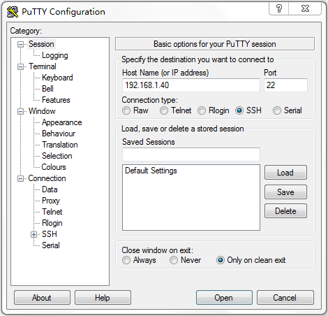
# Launch PuTTY.exe. The PuTTY Configuration window opens. Click Session.
· In the Host Name (or IP address) field, enter IP address 192.168.1.40 of the SSH server.
· In the Port field, enter 22.
· Select SSH as the connection type.
Figure 2 Configuring the SSH client
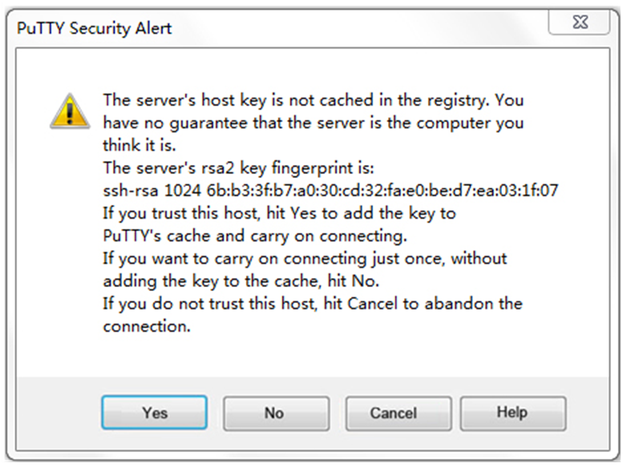
# Click Open. The PuTTY Security Alert dialog box opens.
Figure 3 PuTTY Security Alert
# Click Yes. Enter username client001 and password hello12345 (not shown on the interface) to log in to the SSH server.
Figure 4 Logging in to the SSH server
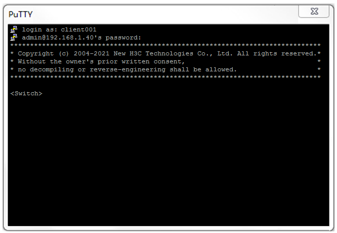
The output shows that you have successfully log in to the switch and can use all commands available on the switch.
Configuration files
#
vlan 2
#
interface Vlan-interface2
ip address 192.168.1.40 255.255.255.0
#
interface Ten-GigabitEthernet1/0/2
port access vlan 2
#
line vty 0 63
authentication-mode scheme
#
ssh server enable
#
local-user client001 class manage
password hash $h$6$CqMnWdX6LIW/hz2Z$4+0Pumk+A98VlGVgqN3n/mEi7hJka9fEZpRZIpSNi9b
cBEXhpvIqaYTvIVBf7ZUNGnovFsqW7nYxjoToRDvYBg==
service-type ssh
authorization-attribute user-role network-admin
authorization-attribute user-role network-operator
#
Related documentation
· SSH configuration in the security configuration guide for the device.
· SSH commands in the security command reference for the device.
Configuring the device as an SSH client
Introduction
The following information uses an example to describe the basis procedure for configuring the device as an SSH client.
Network configuration
As shown in Figure 5, configure the switches to meet the following requirements:
· Switch A acts as the SSH client.
· Switch B acts as the SSH server and uses password authentication to authenticate the SSH client locally.
· Set the username of the client to client001 and password to hello12345 for login. After the user logs in to Switch B from Switch A, the user can use all commands to configure Switch B.

Procedure
1. Configure Switch A:
# Create VLAN 2 and assign Ten-GigabitEthernet 1/0/2 to VLAN 2.
<SwitchA> system-view
[SwitchA] vlan 2
[SwitchA-vlan2] port ten-gigabitethernet 1/0/2
[SwitchA-vlan2] quit
# Assign an IP address to VLAN-interface 2.
[SwitchA] interface vlan-interface 2
[SwitchA-Vlan-interface2] ip address 192.168.1.56 255.255.255.0
[SwitchA-Vlan-interface2] quit
2. Configure Switch B:
# Configure Switch B as the SSH server. For more information, see "Configuring the device as an SSH server."
Verifying the configuration
Verify that you can successfully log in to Switch B as a network administrator:
# On Switch A, establish an SSH connection to the SSH server (Switch B) at 192.168.1.40.
# Enter username client001 and enter Y to continue accessing the server without authenticating the server.
# Enter N to not save the server public key.
|
|
NOTE: If you enter Y to save the server public key, when the server public key changes, execute the delete SSH client server public key command in the system view of Switch A to delete the saved public key, so that you can establish a connection to the server again. |
# Enter password hello12345 (not shown on the interface) to log in to the SSH server.
<SwitchA> ssh2 192.168.1.40
Username: client001
Press CTRL+C to abort.
Connecting to 192.168.1.40 port 22.
The server is not authenticated. Continue? [Y/N]:Y
Do you want to save the server public key? [Y/N]:N
Enter password:
******************************************************************************
* Copyright (c) 2004-2021 New H3C Technologies Co., Ltd. All rights reserved.*
* Without the owner's prior written consent, *
* no decompiling or reverse-engineering shall be allowed. *
******************************************************************************
<SwitchB>
Configuration files
· Switch A
#
vlan 2
#
interface Vlan-interface2
ip address 192.168.1.56 255.255.255.0
#
interface Ten-GigabitEthernet1/0/2
port link-mode bridge
port access vlan 2
#
· Switch B
See "Configuration files."
Related documentation
· SSH configuration in the security configuration guide for the device.
· SSH commands in the security command reference for the device.