- Table of Contents
-
- H3C Campus Fixed-Port Switches CLI-Based Quick Start Configuration Guide-6W101
- 01-H3C Devices CLI Reference
- 02-Login Management Quick Start Configuration Guide
- 03-Configuration File Management Quick Start Configruation Guide
- 04-Software Upgrade Quick Start Configuration Guide
- 05-Device Management Quick Start Configuration Guide
- 06-NTP Quick Start Configuration Guide
- 07-RBAC Quick Start Configuration Guide
- 08-IRF Quick Start Configuration Guide
- 09-Ethernet Interface Quick Start Configuration Guide
- 10-VLAN Quick Start Configuration Guide
- 11-Port Isolation Quick Start Configuration Guide
- 12-Loop Detection Quick Start Configuration Guide
- 13-QinQ Quick Start Configuration Guide
- 14-MAC Address Table Quick Start Configuration Guide
- 15-Ethernet Link Aggregation Quick Start Configuration Guide
- 16-Spanning Tree Quick Start Configuration Guide
- 17-DHCP Quick Start Configuration Guide
- 18-OSPF Quick Start Configuration Guide
- 19-Static Routing Quick Start Configuration Guide
- 20-Basic RIP Quick Start Configuration Guide
- 21-PBR Quick Start Configuration Guide
- 22-IGMP Snooping Quick Start Configuration Guide
- 23-Packet Filtering Quick Start Configuration Guide
- 24-QoS Quick Start Configuration Guide
- 25-IP Source Guard Quick Start Configuration Guide
- 26-SSH Quick Start Configuration Guide
- 27-Port Security Quick Start Configuration Guide
- 28-VRRP Quick Start Configuration Guide
- 29-PoE Quick Start Configuration Guide
- 30-Mirroring Quick Start Configuration Guide
- 31-Information Center Quick Start Configuration Guide
- 32-SNMP Quick Start Configuration Guide
- 33-LAN Networks Quick Start Configuration Guide
- Related Documents
-
| Title | Size | Download |
|---|---|---|
| 17-DHCP Quick Start Configuration Guide | 126.60 KB |
DHCP Quick Start Configuration Guide
Copyright © 2022 New H3C Technologies Co., Ltd. All rights reserved.
No part of this manual may be reproduced or transmitted in any form or by any means without prior written consent of New H3C Technologies Co., Ltd.
Except for the trademarks of New H3C Technologies Co., Ltd., any trademarks that may be mentioned in this document are the property of their respective owners.
The information in this document is subject to change without notice.
Configuring dynamic IPv4 address assignment
Introduction
The following example describes the basic procedure to configure an interface as a DHCP server for dynamic IPv4 address assignment.
Network configuration
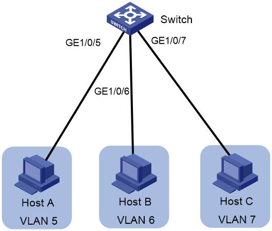
As shown in Figure 1, the core switch has three VLANs. Host A, Host B, and Host C are in VLAN 5, VLAN 6, and VLAN 7, respectively. Configure the core switch as a DHCP server to meet the following requirements:
· The clients on subnets 192.168.5.0/24, 192.168.6.0/24, and 192.168.7.0/24 can obtain IP addresses through DHCP.
· The IP addresses of VLAN-interface 5, VLAN-interface 6, and VLAN-interface 7 on the switch are 192.168.5.254/24, 192.168.6.254/24, and 192.168.7.254/24, respectively.
· For the hosts in subnet 192.168.5.0/24, the DNS server IP address is 192.168.5.100 and the gateway IP address is 192.168.5.254/24.
· For the hosts in subnet 192.168.6.0/24, the DNS server IP address is 192.168.6.100 and the gateway IP address is 192.168.6.254/24.
· For the hosts in subnet 192.168.7.0/24, the DNS server IP address is 192.168.7.100 and the gateway IP address is 192.168.7.254/24.
Procedure
# Enable DHCP on the switch.
<Switch> system-view
[Switch] dhcp enable
[Switch] vlan 5
[Switch-vlan5] port gigabitEthernet 1/0/5
[Switch-vlan5] quit
[Switch]vlan 6
[Switch-vlan6] port gigabitEthernet 1/0/6
[Switch-vlan6] quit
[Switch]vlan 7
[Switch-vlan7] port gigabitEthernet 1/0/7
[Switch-vlan7] quit
# Assign IP addresses to VLAN-interface 5, VLAN-interface 6, and VLAN-interface 7. Each VLAN interface acts as the gateway in the VLAN to which the interface belongs.
[Switch] interface vlan-interface 5
[Switch-Vlan-interface5] ip address 192.168.5.254 255.255.255.0
[Switch-Vlan-interface5] quit
[Switch]interface vlan-interface 6
[Switch-Vlan-interface6] ip address 192.168.6.254 255.255.255.0
[Switch-Vlan-interface6] quit
[Switch]interface vlan-interface 7
[Switch-Vlan-interface7] ip address 192.168.7.254 255.255.255.0
[Switch-Vlan-interface7] quit
# (Optional.) Exclude specific IP addresses (such as DNS server IP addresses) from dynamic IP address assignment.
[Switch] dhcp server forbidden-ip 192.168.5.100
[Switch] dhcp server forbidden-ip 192.168.6.100
[Switch] dhcp server forbidden-ip 192.168.7.100
# Create IP address pool 5 to assign IP addresses to the clients on subnet 192.168.5.0/24.
[Switch] dhcp server ip-pool 5
[Switch-dhcp-pool-5] network 192.168.5.0 mask 255.255.255.0
[Switch-dhcp-pool-5] dns-list 192.168.5.100
[Switch-dhcp-pool-5] gateway-list 192.168.5.254
[Switch-dhcp-pool-5] quit
# Create IP address pool 6 to assign IP addresses to the clients on subnet 192.168.6.0/24.
[Switch] dhcp server ip-pool 6
[Switch-dhcp-pool-6] network 192.168.6.0 mask 255.255.255.0
[Switch-dhcp-pool-6] dns-list 192.168.6.100
[Switch-dhcp-pool-6] gateway-list 192.168.6.254
[Switch-dhcp-pool-6] quit
# Create IP address pool 7 to assign IP addresses to the clients on subnet 192.168.7.0/24.
[Switch] dhcp server ip-pool 7
[Switch-dhcp-pool-7] network 192.168.7.0 mask 255.255.255.0
[Switch-dhcp-pool-7] dns-list 192.168.7.100
[Switch-dhcp-pool-7] gateway-list 192.168.7.254
[Switch-dhcp-pool-7] quit
Verifying the configuration
# Check the IP addresses and other network settings of Host A, Host B, and Host C. Use the display dhcp server ip-in-use command to view the IP addresses assigned by the DHCP server.
[Switch] display dhcp server ip-in-use
IP address Client-identifier/ Lease expiration Type
Hardware address
192.168.5.1 0031-3865-392e-6262- Jan 14 22:25:03 2021 Auto(C)
3363-2e30-3230-352d-
4745-302f-30
192.168.6.2 0031-fe65-4203-7e02- Jan 14 22:25:03 2021 Auto(C)
3063-5b30-3230-4702-
620e-712f-5e
192.168.7.3 3030-3030-2e30-3030- Jan 9 10:45:11 2021 Auto(C)
662e-3030-3033-2d45-
7568-6572-1e
The output shows that the DHCP server can assign IP addresses and other network settings to the clients on subnets 192.168.5.0/24, 192.168.6.0/24, and 192.168.7.0/24 correctly.
Configuration files
#
dhcp enable
dhcp server forbidden-ip 192.168.5.100
dhcp server forbidden-ip 192.168.6.100
dhcp server forbidden-ip 192.168.7.100
#
vlan 5 to 7
#
dhcp server ip-pool 5
gateway-list 192.168.5.254
network 192.168.5.0 mask 255.255.255.0
dns-list 192.168.5.100
#
dhcp server ip-pool 6
gateway-list 192.168.6.254
network 192.168.6.0 mask 255.255.255.0
dns-list 192.168.6.100
#
dhcp server ip-pool 7
gateway-list 192.168.7.254
network 192.168.7.0 mask 255.255.255.0
dns-list 192.168.7.100
#
interface Vlan-interface5
ip address 192.168.5.254 255.255.255.0
#
interface Vlan-interface6
ip address 192.168.6.254 255.255.255.0
#
interface Vlan-interface7
ip address 192.168.7.254 255.255.255.0
#
interface GigabitEthernet1/0/5
port link-mode bridge
port access vlan 5
#
interface GigabitEthernet1/0/6
port link-mode bridge
port access vlan 6
#
interface GigabitEthernet1/0/7
port link-mode bridge
port access vlan 7
#
Related documentation
· DHCP configuration in the Layer 3 IP services configuration guide for the device.
· DHCP commands in the Layer 3 IP services command reference for the device.
Configuring DHCP relay agent
Introduction
The following example describes the basic procedure to configure an interface as a DHCP relay agent. The DHCP relay agent enables clients to obtain IP addresses and configuration parameters from a DHCP server on another subnet.
Network configuration
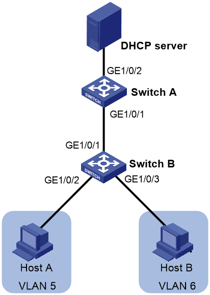
As shown in Figure 2, Switch A acts as the core switch and has two VLANs. Host A and Host B are in VLAN 5 and VLAN 6, respectively. The DHCP server and the hosts run on different subnets and Switch A is the gateway for these hosts. Configure the network to meet the following requirements:
· The DHCP clients run on subnets 192.168.5.0/24 and 192.168.6.0/24, and the DHCP server IP address is 192.168.7.100/24.
· Switch A acts as the DHCP relay agent for clients, so these clients can obtain IP addresses in subnets 192.168.5.0/24 and 192.168.6.0/24, and other network settings from the DHCP server.
Procedure
1. Configure Switch B.
# Create VLAN 5 and VLAN 6, and then assign GigabitEthernet 1/0/2 and GigabitEthernet 1/0/3 to VLAN 5 and VLAN 6, respectively.
<SwitchB> system-view
[SwitchB] vlan 5
[SwitchB-vlan5] port gigabitEthernet 1/0/2
[SwitchB-vlan5] quit
[SwitchB] vlan 6
[SwitchB-vlan6] port gigabitEthernet 1/0/3
[SwitchB-vlan6] quit
# Configure GigabitEthernet 1/0/1 as a trunk port, and allow packets from all VLANs to pass through the trunk port.
[SwitchB] interface gigabitEthernet 1/0/1
[SwitchB-GigabitEthernet1/0/1] port link-type trunk
[SwitchB-GigabitEthernet1/0/1] port trunk permit vlan all
[SwitchB-GigabitEthernet1/0/1] quit
2. Configure Switch A.
# Enable DHCP.
<SwitchA> system-view
[SwitchA] dhcp enable
# Create VLAN 5, VLAN 6, and VLAN 7, and then assign GigabitEthernet 1/0/2 to VLAN 7.
[SwitchA] vlan 5 to 7
[SwitchA] interface GigabitEthernet 1/0/2
[SwitchA-GigabitEthernet1/0/2] port access vlan 7
[SwitchA-GigabitEthernet1/0/2] quit
# Configure GigabitEthernet 1/0/1 as a trunk port, and allow packets from all VLANs to pass through the trunk port.
[SwitchA] interface gigabitEthernet 1/0/1
[SwitchA-GigabitEthernet1/0/1] port link-type trunk
[SwitchA-GigabitEthernet1/0/1] port trunk permit vlan all
[SwitchA-GigabitEthernet1/0/1] quit
# Assign an IP address to VLAN 5, VLAN 6, and VLAN 7, respectively.
[SwitchA] interface vlan-interface 5
[SwitchA-Vlan-interface5] ip address 192.168.5.1 255.255.255.0
[SwitchA-Vlan-interface5] quit
[SwitchA] interface vlan-interface 6
[SwitchA-Vlan-interface6] ip address 192.168.6.1 255.255.255.0
[SwitchA-Vlan-interface6] quit
[SwitchA]interface vlan-interface 7
[SwitchA-Vlan-interface7] ip address 192.168.7.1 255.255.255.0
[SwitchA-Vlan-interface7] quit
# Enable the DHCP relay agent mode on VLAN-interface 5.
[SwitchA] interface vlan-interface 5
[SwitchA-Vlan-interface5] dhcp select relay
# Assign IP address 192.168.7.100 to the DHCP server.
[SwitchA-Vlan-interface5] dhcp relay server-address 192.168.7.100
# Enable the DHCP relay agent mode on VLAN-interface 6.
[SwitchA] interface vlan-interface 6
[SwitchA-Vlan-interface6] dhcp select relay
# Assign IP address 192.168.7.100 to the DHCP server.
[SwitchA-Vlan-interface6] dhcp relay server-address 192.168.7.100
3. Configure DHCP server. Details are not shown.
# Assign IP address 192.168.7.100/24 to the NIC of the DHCP server.
# Configure IP address 192.168.7.1 as the gateway for the DHCP server.
# Make sure the DHCP server can ping 192.168.5.1 and 192.168.6.1.
Verifying the configuration
Check whether Host A and Host B can obtain IP addresses and other network settings from the DHCP server.
Configuration files
· Switch B:
vlan 5 to 6
#
interface GigabitEthernet1/0/1
port link-mode bridge
port link-type trunk
port trunk permit vlan all
#
interface GigabitEthernet1/0/2
port link-mode bridge
port access vlan 5
#
interface GigabitEthernet1/0/3
port link-mode bridge
port access vlan 6
· Switch A:
#
dhcp enable
#
vlan 5 to 7
#
interface Vlan-interface5
ip address 192.168.5.1 255.255.255.0
dhcp select relay
dhcp relay server-address 192.168.7.100
#
interface Vlan-interface6
ip address 192.168.6.1 255.255.255.0
dhcp select relay
dhcp relay server-address 192.168.7.100
#
interface Vlan-interface7
ip address 192.168.7.1 255.255.255.0
#
interface Ten-GigabitEthernet1/0/1
port link-mode bridge
port link-type trunk
port trunk permit vlan all
#
interface Ten-GigabitEthernet1/0/2
port link-mode bridge
port access vlan 7
#
Related documentation
· DHCP configuration in the Layer 3 IP services configuration guide for the device.
· DHCP commands in the Layer 3 IP services command reference for the device.
Configuring DHCP snooping
Introduction
The following example describes the basic procedure to configure DHCP snooping.
Network configuration
As shown in Figure 3, the switch is connected to the authorized DHCP server through GigabitEthernet 1/0/1, to the unauthorized DHCP server through GigabitEthernet 1/0/3, and to the DHCP client through GigabitEthernet 1/0/2. Configure the network to meet the following requirements:
· Only the port connected to the authorized DHCP server can forward the responses from the DHCP server.
· The DHCP snooping device records clients' IP-to-MAC bindings by reading DHCP-ACK messages received from the trusted port and the DHCPREQUEST messages.

Procedure
# Enable global DHCP snooping.
<Switch> system-view
[Switch] dhcp snooping enable
# Configure GigabitEthernet 1/0/1 as a trusted port.
[Switch] interface gigabitethernet 1/0/1
[Switch-GigabitEthernet1/0/1] dhcp snooping trust
[Switch-GigabitEthernet1/0/1] quit
# Enable recording clients' IP-to-MAC bindings on GigabitEthernet 1/0/2.
[Switch] interface gigabitethernet 1/0/2
[Switch-GigabitEthernet1/0/2] dhcp snooping binding record
[Switch-GigabitEthernet1/0/2] quit
Verifying the configuration
# Verify that the DHCP client can obtain an IP address and other configuration parameters only from the authorized DHCP server. (Details not shown.)
# Use the display dhcp snooping binding command to check the DHCP snooping entry recorded for the client.
Configuration files
#
dhcp snooping enable
#
interface GigabitEthernet1/0/1
port link-mode bridge
dhcp snooping trust
#
interface Ten-GigabitEthernet1/0/2
port link-mode bridge
dhcp snooping binding record
#
Related documentation
· DHCP configuration in the Layer 3 IP services configuration guide for the device.
· DHCP commands in the Layer 3 IP services command reference for the device.
Configuring dynamic IPv6 address assignment
Introduction
The following example describes the basic procedure to configure an interface as a DHCPv6 server for dynamic IPv6 address assignment.
Network configuration
As shown in Figure 4, Switch A and Switch B are gateway devices for internal hosts. Configure the network to meet the following requirements:
· Switch A and Switch B are connected through Ethernet interfaces. The interfaces of each switch operate in different VLAN and have IPv6 addresses.
· VLAN-interface 1 and VLAN-interface 3 operate in DHCPv6 server mode to assign IPv6 addresses to hosts.
· Switch A and Switch B have IPv6 static routes to ensure network connectivity.

Procedure
1. Configure Switch A.
# Create VLAN 1 and assign GigabitEthernet 1/0/2 to VLAN 1.
<SwitchA> system-view
[SwitchA] vlan 1
[SwitchA-vlan1] port gigabitethernet 1/0/2
[SwitchA-vlan1] quit
# Create VLAN 2 and assign GigabitEthernet 1/0/1 to VLAN 2.
[SwitchA] vlan 2
[SwitchA-vlan2] port gigabitethernet 1/0/1
[SwitchA-vlan2] quit
# Specify an IPv6 global unicast address for VLAN-interface 2.
[SwitchA] interface vlan-interface 2
[SwitchA-Vlan-interface2] ipv6 address 3001::1/64
[SwitchA-Vlan-interface2] quit
# Specify an IPv6 global unicast address for VLAN-interface 1 and disable RA message suppression on VLAN-interface 1.
[SwitchA] interface vlan-interface 1
[SwitchA-Vlan-interface1] ipv6 address 2001::1/64
[SwitchA-Vlan-interface1] undo ipv6 nd ra halt
# Apply an IPv6 address pool to VLAN-interface 1.
[SwitchA-Vlan-interface1] ipv6 dhcp server apply pool 1 allow-hint rapid-commit
# Set the M flag to 1 in RA advertisements to be sent on VLAN-interface 1. Hosts that receive the RA advertisements will obtain IPv6 addresses through DHCPv6.
[SwitchA-Vlan-interface1] ipv6 nd autoconfig managed-address-flag
# Set the O flag to 1 in RA advertisements to be sent on VLAN-interface 1. Hosts that receive the RA advertisements will obtain configuration information other than IPv6 address through DHCPv6.
[SwitchA-Vlan-interface1] ipv6 nd autoconfig other-flag
# Configure VLAN-interface 1 to operate in DHCPv6 server mode.
[SwitchA-Vlan-interface1] ipv6 dhcp select server
[SwitchA-Vlan-interface1] quit
# Create IPv6 address pool 1.
[SwitchA] ipv6 dhcp pool 1
[SwitchA-dhcp6-pool-1] network 2001::/64
[SwitchA-dhcp6-pool-1] dns-server 1::1
[SwitchA-dhcp6-pool-1] quit
# Configure an IPv6 static route destined for 4001::/64 and the next hop of the route is 3001::2.
[SwitchA] ipv6 route-static 4001:: 64 3001::2
# Save the configuration.
[SwitchA] save force
# Create VLAN 2 and assign GigabitEthernet 1/0/1 to VLAN 2.
<SwitchB> system-view
[SwitchB] vlan 2
[SwitchB-vlan2] port gigabitethernet 1/0/1
[SwitchB-vlan2] quit
# Create VLAN 3 and assign GigabitEthernet 1/0/2 to VLAN 3.
[SwitchB] vlan 3
[SwitchB-vlan3] port gigabitethernet 1/0/2
[SwitchB-vlan3] quit
# Specify an IPv6 global unicast address for VLAN-interface 2.
[SwitchB] interface vlan-interface 2
[SwitchB-Vlan-interface2] ipv6 address 3001::2/64
[SwitchB-Vlan-interface2] quit
# Specify an IPv6 global unicast address for VLAN-interface 3 and disable RA message suppression on VLAN-interface 3.
[SwitchB] interface vlan-interface 3
[SwitchB-Vlan-interface3] ipv6 address 4001::1/64
[SwitchB-Vlan-interface3] undo ipv6 nd ra halt
# Apply an IPv6 address pool to VLAN-interface 3.
[SwitchB-Vlan-interface3] ipv6 dhcp server apply pool 1 allow-hint rapid-commit
# Set the M flag to 1 in RA advertisements to be sent on VLAN-interface 3. Hosts that receive the RA advertisements will obtain IPv6 addresses through DHCPv6.
[SwitchB-Vlan-interface3] ipv6 nd autoconfig managed-address-flag
# Set the O flag to 1 in RA advertisements to be sent on VLAN-interface 3. Hosts that receive the RA advertisements will obtain configuration information other than IPv6 address through DHCPv6.
[SwitchB-Vlan-interface3] ipv6 nd autoconfig other-flag
# Configure VLAN-interface 3 to operate in DHCPv6 server mode.
[SwitchB-Vlan-interface3] ipv6 dhcp select server
[SwitchB-Vlan-interface3] quit
# Create IPv6 address pool 1.
[SwitchB] ipv6 dhcp pool 1
[SwitchB-dhcp6-pool-1] network 4001::/64
[SwitchB-dhcp6-pool-1] dns-server 1::1
[SwitchB-dhcp6-pool-1] quit
# Configure an IPv6 static route destined for 2001::/64 and the next hop of the route is 3001::1.
[SwitchB] ipv6 route-static 2001:: 64 3001::1
# Save the configuration.
[SwitchB] save force
3. Configure Host A.
Configure IPv6 on Host A, and then enable Host A to use DHCPv6 for IPv6 address acquisition.
4. Configure Host B.
Configure IPv6 on Host B, and then enable Host B to use DHCPv6 for IPv6 address acquisition.
Verifying the configuration
# View the IPv6 addresses assigned by the DHCPv6 server on Switch A.
[SwitchA] display ipv6 dhcp server ip-in-use
Pool: 1
IPv6 address Type Lease expiration
2001::2 Auto(C) Sep 30 11:45:07 2021
# View information about the neighbors of GigabitEthernet 1/0/2 on Switch A.
[SwitchA] display ipv6 neighbors interface gigabitethernet 1/0/2
Type: S-Static D-Dynamic O-Openflow R-Rule IS-Invalid static
IPv6 address MAC address VLAN/VSI Interface State T Aging
2001::2 b025-0b54-0106 -- GE1/0/2 REACH D 29
FE80::B225:BFF:FE54:106 b025-0b54-0106 -- GE1/0/2 REACH D 18
The output shows that Host A has obtained IPv6 global unicast address 2001::2.
# View the IPv6 addresses assigned by the DHCPv6 server on Switch B.
[SwitchB] display ipv6 dhcp server ip-in-use
Pool: 1
IPv6 address Type Lease expiration
4001::2 Auto(C) Sep 30 14:05:49 2021
# View information about the neighbors of GigabitEthernet 1/0/2 on Switch B.
[SwitchB] display ipv6 neighbors interface gigabitethernet 1/0/2
Type: S-Static D-Dynamic O-Openflow R-Rule IS-Invalid static
IPv6 address MAC address VLAN/VSI Interface State T Aging
4001::2 b043-5415-0406 -- GE1/0/2 REACH D 3
FE80::B243:54FF:FE15:406 b043-5415-0406 -- GE1/0/2 REACH D 44
The output shows that Host B has obtained IPv6 global unicast address 4001::2.
# Check whether Host A and Host B can ping each other successfully.
Configuration files
· Switch A:
#
vlan 1
#
vlan 2
#
ipv6 dhcp pool 1
network 2001::/64
dns-server 1::1
#
interface Vlan-interface1
ipv6 dhcp select server
ipv6 dhcp server apply pool 1 allow-hint rapid-commit
ipv6 address 2001::1/64
ipv6 nd autoconfig managed-address-flag
undo ipv6 nd ra halt
#
interface Vlan-interface2
ipv6 address 3001::1/64
#
interface GigabitEthernet1/0/1
port link-mode bridge
port access vlan 2
#
interface GigabitEthernet1/0/2
port link-mode bridge
#
ipv6 route-static 4001:: 64 3001::2
#
· Switch B:
#
vlan 2 to 3
#
ipv6 dhcp pool 1
network 4001::/64
dns-server 1::1
#
interface Vlan-interface2
ipv6 address 3001::2/64
#
interface Vlan-interface3
ipv6 dhcp select server
ipv6 dhcp server apply pool 1 allow-hint rapid-commit
ipv6 address 4001::1/64
ipv6 nd autoconfig managed-address-flag
ipv6 nd autoconfig other-flag
undo ipv6 nd ra halt
#
interface GigabitEthernet1/0/1
port link-mode bridge
port access vlan 2
#
interface GigabitEthernet1/0/2
port link-mode bridge
port access vlan 3
#
ipv6 route-static 2001:: 64 3001::1
#
Related documentation
· DHCPv6 configuration in the Layer 3 IP services configuration guide for the device.
· DHCPv6 commands in the Layer 3 IP services command reference for the device.