- Table of Contents
-
- 09-Security Configuration Guide
- 00-Preface
- 01-AAA configuration
- 02-802.1X configuration
- 03-MAC authentication configuration
- 04-Portal configuration
- 05-Web authentication configuration
- 06-Triple authentication configuration
- 07-Port security configuration
- 08-User profile configuration
- 09-Password control configuration
- 10-Keychain configuration
- 11-Public key management
- 12-PKI configuration
- 13-IPsec configuration
- 14-SSH configuration
- 15-SSL configuration
- 16-TCP attack prevention configuration
- 17-Attack detection and prevention configuration
- 18-IP source guard configuration
- 19-ARP attack protection configuration
- 20-ND attack defense configuration
- 21-uRPF configuration
- 22-SAVI configuration
- 23-MFF configuration
- 24-Crypto engine configuration
- 25-FIPS configuration
- 26-MACsec configuration
- 27-802.1X client configuration
- 28-SAVA configuration
- Related Documents
-
| Title | Size | Download |
|---|---|---|
| 19-ARP attack protection configuration | 316.71 KB |
Contents
Configuring ARP attack protection
ARP attack protection tasks at a glance
Configuring unresolvable IP attack protection
About unresolvable IP attack protection
Configuring ARP source suppression
Configuring ARP blackhole routing
Display and maintenance commands for unresolvable IP attack protection
Example: Configuring unresolvable IP attack protection
Configuring ARP packet rate limit
Configuring source MAC-based ARP attack detection
Display and maintenance commands for source MAC-based ARP attack detection
Example: Configuring source MAC-based ARP attack detection
Configuring ARP packet source MAC consistency check
About ARP packet source MAC consistency check
Configuring ARP active acknowledgement
Example: Configuring authorized ARP on a DHCP server
Example: Configuring authorized ARP on a DHCP relay agent
Configuring ARP attack detection
Software version and feature compatibility
Restrictions and guidelines: ARP attack detection
Configuring user validity check
Configuring ARP packet validity check
Configuring ARP restricted forwarding
Ignoring ingress ports of ARP packets during user validity check
Configuring ARP attack detection for a VSI
Enabling ARP attack detection logging
Display and maintenance commands for ARP attack detection
Example: Configuring user validity check
Example: Configuring user validity check and ARP packet validity check
Example: Configuring ARP restricted forwarding
Configuring ARP scanning and fixed ARP
Configuring automatic ARP scanning
Configuring ARP gateway protection
Example: Configuring ARP gateway protection
Example: Configuring ARP filtering
Configuring ARP sender IP address checking
About ARP sender IP address checking
Example: Configuring ARP sender IP address checking
Configuring ARP attack protection
About ARP attack protection
The device can provide multiple features to detect and prevent ARP attacks and viruses in the LAN. An attacker can exploit ARP vulnerabilities to attack network devices in the following ways:
· Sends a large number of unresolvable IP packets to have the receiving device busy with resolving IP addresses until its CPU is overloaded. Unresolvable IP packets refer to IP packets for which ARP cannot find corresponding MAC addresses.
· Sends a large number of ARP packets to overload the CPU of the receiving device.
· Acts as a trusted user or gateway to send ARP packets so the receiving devices obtain incorrect ARP entries.
ARP attack protection tasks at a glance
All ARP attack protection tasks are optional.
· Preventing flood attacks
¡ Configuring unresolvable IP attack protection
¡ Configuring ARP packet rate limit
¡ Configuring source MAC-based ARP attack detection
· Preventing user and gateway spoofing attacks
¡ Configuring ARP packet source MAC consistency check
¡ Configuring ARP active acknowledgement
¡ Example: Configuring authorized ARP on a DHCP relay agent
¡ Configuring ARP attack detection
¡ Configuring ARP packet validity check
¡ Configuring ARP restricted forwarding
¡ Ignoring ingress ports of ARP packets during user validity check
¡ Enabling ARP attack detection logging
¡ Configuring ARP scanning and fixed ARP
¡ Configuring ARP gateway protection
¡ Example: Configuring ARP gateway protection
¡ Configuring ARP sender IP address checking
Configuring unresolvable IP attack protection
About unresolvable IP attack protection
If a device receives a large number of unresolvable IP packets from a host, the following situations can occur:
· The device sends a large number of ARP requests, overloading the target subnets.
· The device keeps trying to resolve the destination IP addresses, overloading its CPU.
To protect the device from such IP attacks, you can configure the following features:
· ARP source suppression—Stops resolving packets from an IP address if the number of unresolvable IP packets from the IP address exceeds the upper limit within 5 seconds. The device continues ARP resolution when the interval elapses. This feature is applicable if the attack packets have the same source addresses.
· ARP blackhole routing—Creates a blackhole route destined for an unresolved IP address. The device drops all matching packets until the blackhole route is deleted. A blackhole route is deleted when its aging timer is reached or the route becomes reachable.
After a blackhole route is created for an unresolved IP address, the device immediately starts the first ARP blackhole route probe by sending an ARP request. If the resolution fails, the device continues probing according to the probe settings. If the IP address resolution succeeds in a probe, the device converts the blackhole route to a normal route. If an ARP blackhole route ages out before the device finishes all probes, the device deletes the blackhole route and does not perform the remaining probes.
This feature is applicable regardless of whether the attack packets have the same source addresses.
Configuring ARP source suppression
1. Enter system view.
system-view
2. Enable ARP source suppression.
arp source-suppression enable
By default, ARP source suppression is disabled.
3. Set the maximum number of unresolvable packets that the device can process per source IP address within 5 seconds.
arp source-suppression limit limit-value
By default, the maximum number is 10.
Configuring ARP blackhole routing
Restrictions and guidelines
Set the ARP blackhole route probe count to a big value, for example, 25. If the device fails to reach the destination IP address temporarily and the probe count is too small, all probes might finish before the problem is resolved. As a result, non-attack packets will be dropped. This setting can avoid such situation.
Procedure
1. Enter system view.
system-view
2. Enable ARP blackhole routing.
arp resolving-route enable
By default, ARP blackhole routing is enabled.
3. (Optional.) Set the number of ARP blackhole route probes for each unresolved IP address.
arp resolving-route probe-count count
The default setting is three probes.
4. (Optional.) Set the interval at which the device probes ARP blackhole routes.
arp resolving-route probe-interval interval
The default setting is 1 second.
Display and maintenance commands for unresolvable IP attack protection
Execute display commands in any view.
|
Task |
Command |
|
Display ARP source suppression configuration information. |
display arp source-suppression |
Example: Configuring unresolvable IP attack protection
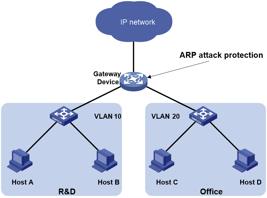
Network configuration
As shown in Figure 1, a LAN contains two areas: an R&D area in VLAN 10 and an office area in VLAN 20. Each area connects to the gateway (Device) through an access switch.
A large number of ARP requests are detected in the office area and are considered an attack caused by unresolvable IP packets. To prevent the attack, configure ARP source suppression or ARP blackhole routing.
Procedure
· If the attack packets have the same source address, configure ARP source suppression:
# Enable ARP source suppression.
<Device> system-view
[Device] arp source-suppression enable
# Configure the device to process a maximum of 100 unresolvable packets per source IP address within 5 seconds.
[Device] arp source-suppression limit 100
· If the attack packets have different source addresses, configure ARP blackhole routing:
# Enable ARP blackhole routing.
[Device] arp resolving-route enable
Configuring ARP packet rate limit
About this task
The ARP packet rate limit feature allows you to limit the rate of ARP packets delivered to the CPU. An ARP attack detection-enabled device will send all received ARP packets to the CPU for inspection. Processing excessive ARP packets will make the device malfunction or even crash. To solve this problem, configure ARP packet rate limit. When the receiving rate of ARP packets on the interface exceeds the rate limit, those packets are discarded.
You can enable sending notifications to the SNMP module or enable logging for ARP packet rate limit.
· If notification sending is enabled, the device sends the highest threshold-crossed ARP packet rate within the sending interval in a notification to the SNMP module. You must use the snmp-agent target-host command to set the notification type and target host. For more information about notifications, see Network Management and Monitoring Command Reference.
· If logging for ARP packet rate limit is enabled, the device sends the highest threshold-crossed ARP packet rate within the sending interval in a log message to the information center. You can configure the information center module to set the log output rules. For more information about information center, see Network Management and Monitoring Configuration Guide.
Restrictions and guidelines
As a best practice, configure this feature when ARP attack detection, ARP snooping, or MFF is enabled, or when ARP flood attacks are detected.
If excessive notifications and log messages are sent for ARP packet rate limit, you can increase notification and log message sending interval.
If you enable notification sending and logging for ARP packet rate limit on a Layer 2 aggregate interface, the features apply to all aggregation member ports.
This feature is mutually exclusive with the source MAC-based ARP packet rate limit feature configured by using the arp rate-limit source-mac command.
Procedure
1. Enter system view.
system-view
2. (Optional.) Enable SNMP notifications for ARP packet rate limit.
snmp-agent trap enable arp [ rate-limit ]
By default, SNMP notifications for ARP packet rate limit are disabled.
3. (Optional.) Enable logging for ARP packet rate limit.
arp rate-limit log enable
By default, logging for ARP packet rate limit is disabled.
4. (Optional.) Set the notification and log message sending interval.
arp rate-limit log interval interval
By default, the device sends notifications and log messages every 60 seconds.
5. Enter interface view.
interface interface-type interface-number
Supported interface types include Layer 2 Ethernet interface, Layer 3 Ethernet interface, Layer 3 aggregate interface, and Layer 2 aggregate interface.
6. Enable ARP packet rate limit.
arp rate-limit [ pps ]
By default, ARP packet rate limit is enabled.
Configuring source MAC-based ARP attack detection
About this task
This feature checks the number of ARP packets delivered to the CPU. If the number of packets from the same MAC address within 5 seconds exceeds a threshold, the device generates an ARP attack entry for the MAC address. If logging is enabled for source MAC-based ARP attack detection, the device handles the attack by using either of the following methods before the ARP attack entry ages out:
· Monitor—Only generates log messages.
· Filter—Generates log messages and filters out subsequent ARP packets from the MAC address and data packets destined to or originated from the MAC address.
To enable the ARP logging feature, use the arp source-mac log enable command. For information about the ARP logging feature, see ARP in Layer 3—IP Services Configuration Guide.
When an ARP attack entry ages out, ARP packets sourced from the MAC address in the entry can be processed correctly.
Restrictions and guidelines
When you change the handling method from monitor to filter, the configuration takes effect immediately. When you change the handling method from filter to monitor, the device continues filtering packets that match existing attack entries.
You can exclude the MAC addresses of some gateways and servers from this detection. This feature does not inspect ARP packets from those devices even if they are attackers.
Procedure
1. Enter system view.
system-view
2. Enable source MAC-based ARP attack detection and specify the handling method.
arp source-mac { filter | monitor }
By default, this feature is disabled.
3. Set the threshold.
arp source-mac threshold threshold-value
By default, the threshold is 30.
4. Set the aging timer for ARP attack entries.
arp source-mac aging-time time
By default, the lifetime is 300 seconds.
5. (Optional.) Exclude specific MAC addresses from this detection.
arp source-mac exclude-mac mac-address&<1-10>
By default, no MAC address is excluded.
6. Enable logging for source MAC-based ARP attack detection.
arp source-mac log enable
By default, logging for source MAC-based ARP attack detection is disabled.
Display and maintenance commands for source MAC-based ARP attack detection
Execute display commands in any view.
|
Task |
Command |
|
Display ARP attack entries detected by source MAC-based ARP attack detection. |
display arp source-mac { interface interface-type interface-number [ slot slot-number ] | slot slot-number } |
Example: Configuring source MAC-based ARP attack detection
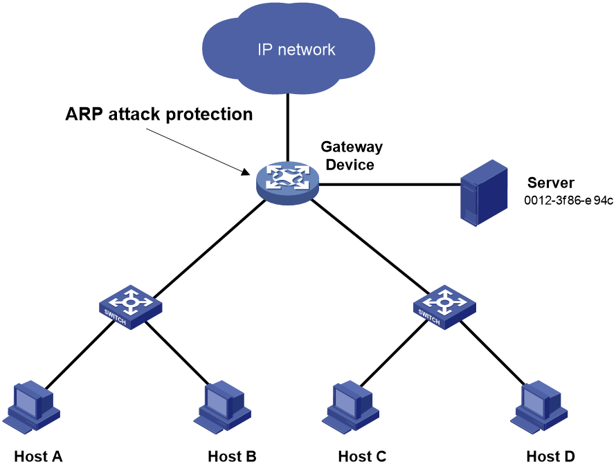
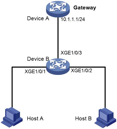
Network configuration
As shown in Figure 2, the hosts access the Internet through a gateway (Device). If malicious users send a large number of ARP requests to the gateway, the gateway might crash and cannot process requests from the clients. To solve this problem, configure source MAC-based ARP attack detection on the gateway.
Figure 2 Network diagram
Procedure
# Enable source MAC-based ARP attack detection, and specify the handling method as filter.
<Device> system-view
[Device] arp source-mac filter
# Set the threshold to 30.
[Device] arp source-mac threshold 30
# Set the lifetime for ARP attack entries to 60 seconds.
[Device] arp source-mac aging-time 60
# Exclude MAC address 0012-3f86-e94c from this detection.
[Device] arp source-mac exclude-mac 0012-3f86-e94c
Configuring ARP packet source MAC consistency check
About ARP packet source MAC consistency check
This feature enables a gateway to filter out ARP packets whose source MAC address in the Ethernet header is different from the sender MAC address in the message body. This feature allows the gateway to learn correct ARP entries.
Procedure
1. Enter system view.
system-view
2. Enable ARP packet source MAC address consistency check.
arp valid-check enable
By default, ARP packet source MAC address consistency check is disabled.
Configuring ARP active acknowledgement
About this task
Use the ARP active acknowledgement feature on gateways to prevent user spoofing.
This feature enables the device to perform active acknowledgement before creating an ARP entry.
· Upon receiving an ARP request that requests the MAC address of the device, the device sends an ARP reply. Then, it sends an ARP request for the sender IP address in the received ARP request to determine whether to create an ARP entry for the sender IP address.
¡ If the device receives an ARP reply within the probe interval, it creates the ARP entry.
¡ If the device does not receive an ARP reply within the probe interval, it does not create the ARP entry.
· Upon receiving an ARP reply, the device examines whether it was the reply to the request that the device has sent.
¡ If it was, the device creates an ARP entry for the sender IP address in the ARP reply.
¡ If it was not, the device sends an ARP request for the sender IP address to determine whether to create an ARP entry for the sender IP address.
- If the device receives an ARP reply within the probe interval, it creates the ARP entry.
- If the device does not receive an ARP reply within the probe interval, it does not create the ARP entry.
To improve validity and reliability of ARP entries, you can enable ARP active acknowledgement in strict mode. In this mode, the device creates ARP entries only for the IP addresses that the device actively initiates the ARP resolution.
Procedure
1. Enter system view.
system-view
2. Enable ARP active acknowledgement.
arp active-ack [ strict ] enable
By default, ARP active acknowledgement is disabled.
For ARP active acknowledgement to take effect in strict mode, make sure ARP blackhole routing is enabled.
Configuring authorized ARP
About authorized ARP
Authorized ARP entries are generated based on the DHCP clients' address leases on the DHCP server or dynamic client entries on the DHCP relay agent. For more information about DHCP server and DHCP relay agent, see Layer 3—IP Services Configuration Guide.
Use this feature to prevent user spoofing and to allow only authorized clients to access network resources.
Procedure
1. Enter system view.
system-view
2. Enter interface view.
interface interface-type interface-number
Supported interface types include Layer 3 Ethernet interface, Layer 3 Ethernet subinterface, Layer 3 aggregate interface, Layer 3 aggregate subinterface, and VLAN interface.
3. Enable authorized ARP on the interface.
arp authorized enable
By default, authorized ARP is disabled.
Example: Configuring authorized ARP on a DHCP server
Network configuration
As shown in Figure 3, configure authorized ARP on Ten-GigabitEthernet 1/0/1 of Device A (a DHCP server) to ensure user validity.

Procedure
1. Configure Device A:
# Specify the IP address for Ten-GigabitEthernet 1/0/1.
<DeviceA> system-view
[DeviceA] interface ten-gigabitethernet 1/0/1
[DeviceA-Ten-GigabitEthernet1/0/1] ip address 10.1.1.1 24
[DeviceA-Ten-GigabitEthernet1/0/1] quit
# Configure DHCP.
[DeviceA] dhcp enable
[DeviceA] dhcp server ip-pool 1
[DeviceA-dhcp-pool-1] network 10.1.1.0 mask 255.255.255.0
[DeviceA-dhcp-pool-1] quit
# Enter Layer 3 Ethernet interface view.
[DeviceA] interface ten-gigabitethernet 1/0/1
# Enable authorized ARP.
[DeviceA-Ten-GigabitEthernet1/0/1] arp authorized enable
[DeviceA-Ten-GigabitEthernet1/0/1] quit
2. Configure Device B:
<DeviceB> system-view
[DeviceB] interface ten-gigabitethernet 1/0/1
[DeviceB-Ten-GigabitEthernet1/0/1] ip address dhcp-alloc
[DeviceB-Ten-GigabitEthernet1/0/1] quit
Verifying the configuration
# Display authorized ARP entry information on Device A.
[DeviceA] display arp all
Type: S-Static D-Dynamic O-Openflow R-Rule M-Multiport I-Invalid
IP address MAC address VLAN/VSI name Interface Aging Type
10.1.1.2 0012-3f86-e94c -- XGE1/0/1 960 D
The output shows that IP address 10.1.1.2 has been assigned to Device B.
Device B must use the IP address and MAC address in the authorized ARP entry to communicate with Device A. Otherwise, the communication fails. Thus user validity is ensured.
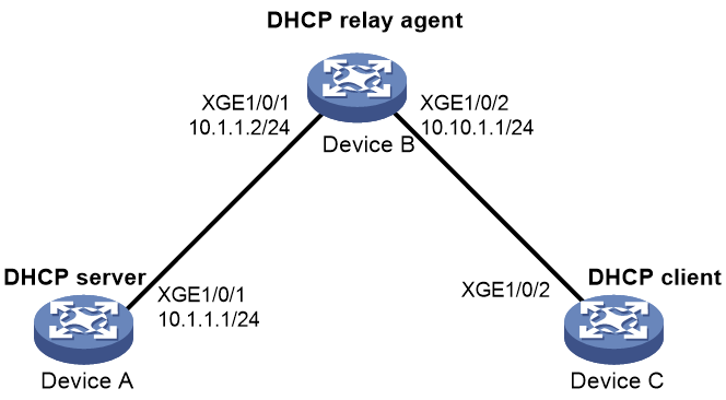
Example: Configuring authorized ARP on a DHCP relay agent
Network configuration
As shown in Figure 4, configure authorized ARP on Ten-GigabitEthernet 1/0/2 of Device B (a DHCP relay agent) to ensure user validity.
Procedure
1. Configure Device A:
# Specify the IP address for Ten-GigabitEthernet 1/0/1.
<DeviceA> system-view
[DeviceA] interface ten-gigabitethernet 1/0/1
[DeviceA-Ten-GigabitEthernet1/0/1] ip address 10.1.1.1 24
[DeviceA-Ten-GigabitEthernet1/0/1] quit
# Configure DHCP.
[DeviceA] dhcp enable
[DeviceA] dhcp server ip-pool 1
[DeviceA-dhcp-pool-1] network 10.10.1.0 mask 255.255.255.0
[DeviceA-dhcp-pool-1] gateway-list 10.10.1.1
[DeviceA-dhcp-pool-1] quit
[DeviceA] ip route-static 10.10.1.0 24 10.1.1.2
2. Configure Device B:
# Enable DHCP.
<DeviceB> system-view
[DeviceB] dhcp enable
# Specify the IP addresses of Ten-GigabitEthernet 1/0/1 and Ten-GigabitEthernet 1/0/2.
[DeviceB] interface ten-gigabitethernet 1/0/1
[DeviceB-Ten-GigabitEthernet1/0/1] ip address 10.1.1.2 24
[DeviceB-Ten-GigabitEthernet1/0/1] quit
[DeviceB] interface ten-gigabitethernet 1/0/2
[DeviceB-Ten-GigabitEthernet1/0/2] ip address 10.10.1.1 24
# Enable DHCP relay agent on Ten-GigabitEthernet 1/0/2.
[DeviceB-Ten-GigabitEthernet1/0/2] dhcp select relay
# Add the DHCP server 10.1.1.1 to DHCP server group 1.
[DeviceB-Ten-GigabitEthernet1/0/2] dhcp relay server-address 10.1.1.1
# Enable authorized ARP.
[DeviceB-Ten-GigabitEthernet1/0/2] arp authorized enable
[DeviceB-Ten-GigabitEthernet1/0/2] quit
# Enable recording of relay entries on the relay agent.
[DeviceB] dhcp relay client-information record
3. Configure Device C:
<DeviceC> system-view
[DeviceC] ip route-static 10.1.1.0 24 10.10.1.1
[DeviceC] interface ten-gigabitethernet 1/0/2
[DeviceC-Ten-GigabitEthernet1/0/2] ip address dhcp-alloc
[DeviceC-Ten-GigabitEthernet1/0/2] quit
Verifying the configuration
# Display authorized ARP information on Device B.
[DeviceB] display arp all
Type: S-Static D-Dynamic O-Openflow R-Rule M-Multiport I-Invalid
IP address MAC address VLAN/VSI name Interface Aging Type
10.10.1.2 0012-3f86-e94c -- XGE1/0/2 960 D
The output shows that Device A assigned the IP address 10.10.1.2 to Device C.
Device C must use the IP address and MAC address in the authorized ARP entry to communicate with Device B. Otherwise, the communication fails. Thus the user validity is ensured.
Configuring ARP attack detection
About ARP attack detection
ARP attack detection enables access devices to block ARP packets from unauthorized clients to prevent user spoofing and gateway spoofing attacks.
ARP attack detection provides the following features:
· User validity check.
· ARP packet validity check.
· ARP restricted forwarding.
· ARP packet ingress port ignoring during user validity check
· ARP attack detection for a VSI.
· ARP attack detection logging.
If both ARP packet validity check and user validity check are enabled, the former one applies first, and then the latter applies.
Do not configure ARP attack detection together with ARP snooping. Otherwise, ARP snooping entries cannot be generated.
Software version and feature compatibility
ARP attack detection is supported only in R6515P06 and later.
Restrictions and guidelines: ARP attack detection
ARP attack detection is supported only on Layer 2 Ethernet interfaces and Layer 2 aggregate interfaces.
A Layer 2 Ethernet interface is enabled with ARP attack detection after you enable ARP attack detection on the interface or in the VLAN to which the interface belongs.
A Layer 2 Ethernet interface is disabled with ARP attack detection only after you disable ARP attack detection both on the interface and in the VLAN to which the interface belongs.
If a Layer 2 Ethernet interface is both enabled with ARP attack detection and configured as an ARP trusted port, the ARP trusted port configuration takes effect. The device does not perform ARP attack detection on packets received on the interface.
Configuring user validity check
About this task
User validity check does not check ARP packets received on ARP trusted interfaces. This feature compares the sender IP and sender MAC in the ARP packet received on an ARP untrusted interface with the matching criteria in the following order:
1. User validity check rules.
¡ If a match is found, the device processes the ARP packet according to the rule.
¡ If no match is found or no user validity check rule is configured, proceeds to step 2.
2. Static IPSG bindings, 802.1X security entries, and DHCP snooping entries.
¡ If a match is found, the device determines that the ARP packet is valid and then forwards the ARP packet.
- If the receiving interface is not the interface in the matching entry, the device performs Layer 3 forwarding on the ARP packet based on the target IP address.
- If the receiving interface is the interface in the matching entry, the device performs Layer 2 forwarding on the ARP packet.
¡ If no match is found, the device discards the ARP packet.
Static IP source guard bindings are created by using the ip source binding command. For more information, see "Configuring IP source guard."
DHCP snooping entries are automatically generated by DHCP snooping. For more information, see Layer 3—IP Services Configuration Guide.
802.1X security entries record the IP-to-MAC mappings for 802.1X clients. After a client passes 802.1X authentication and uploads its IP address to an ARP attack detection enabled device, the device automatically generates an 802.1X security entry. The 802.1X client must be enabled to upload its IP address to the device. For more information, see "Configuring 802.1X."
Restrictions and guidelines
When you configure user validity check, make sure one or more of the following items are configured:
· User validity check rules.
· Static IP source guard bindings.
· DHCP snooping.
· 802.1X.
If none of the items is configured, the device does not perform user validity check and discards all incoming ARP packets on ARP untrusted interfaces.
Specify an IP address, a MAC address, and a VLAN where ARP attack detection is enabled for an IP source guard binding. Otherwise, no ARP packets can match the IP source guard binding.
Configuring user validity check rules
1. Enter system view.
system-view
2. Configure a user validity check rule.
arp detection rule rule-id { deny | permit } ip { ip-address [ mask ] | any } mac { mac-address [ mask ] | any } [ vlan vlan-id ]
By default, no user validity check rules are configured.
Enabling ARP attack detection in a VLAN
1. Enter system view.
system-view
2. Enter VLAN view.
vlan vlan-id
3. Enable ARP attack detection.
arp detection enable
By default, ARP attack detection is disabled. The device does not perform ARP user validity check.
4. (Optional.) Configure an interface that does not require ARP user validity check as a trusted interface.
a. Return to system view.
quit
b. Enter interface view.
interface interface-type interface-number
Supported interface types include Layer 2 Ethernet interface and Layer 2 aggregate interface.
c. Configure the interface as a trusted interface excluded from ARP attack detection.
arp detection trust
By default, an interface is untrusted.
Enabling ARP attack detection on a Layer 2 interface
1. Enter system view.
system-view
2. Enter interface view.
interface interface-type interface-number
Supported interfaces include Layer 2 Ethernet interfaces and Layer 2 aggregate interfaces.
3. Enable ARP attack detection.
arp detection enable
By default, ARP attack detection is disabled. The device does not perform user validity check
Configuring ARP packet validity check
About this task
ARP packet validity check does not check ARP packets received on ARP trusted interfaces. To check ARP packets received on untrusted interfaces, you can specify the following objects to be checked:
· src-mac—Checks whether the sender MAC address in the message body is identical to the source MAC address in the Ethernet header. If they are identical, the packet is forwarded. Otherwise, the packet is discarded.
· dst-mac—Checks the target MAC address of ARP replies. If the target MAC address is all-zero, all-one, or inconsistent with the destination MAC address in the Ethernet header, the packet is considered invalid and discarded.
· ip—Checks the sender and target IP addresses of ARP replies, and the sender IP address of ARP requests. All-one or multicast IP addresses are considered invalid and the corresponding packets are discarded.
Prerequisites
Before you configure ARP packet validity check, you must first configure user validity check. For more information about user validity check configuration, see "Configuring user validity check."
Enabling ARP packet validity check
1. Enter system view.
system-view
2. Enable ARP packet validity check.
arp detection validate { dst-mac | ip | src-mac } *
By default, ARP packet validity check is disabled.
Enabling ARP attack detection in a VLAN
1. Enter system view.
system-view
2. Enter VLAN view.
vlan vlan-id
3. Enable ARP attack detection.
arp detection enable
By default, ARP attack detection is disabled. The device does not perform ARP packet validity check.
4. (Optional.) Configure the interface that does not require ARP packet validity check as a trusted interface.
a. Return to system view.
quit
b. Enter interface view.
interface interface-type interface-number
Supported interface types include Layer 2 Ethernet interface and Layer 2 aggregate interface.
c. Configure the interface as a trusted interface excluded from ARP attack detection.
arp detection trust
By default, an interface is untrusted.
Enabling ARP attack detection on a Layer 2 interface
1. Enter system view.
system-view
2. Enter interface view.
interface interface-type interface-number
Supported interfaces include Layer 2 Ethernet interfaces and Layer 2 aggregate interfaces.
3. Enable ARP attack detection.
arp detection enable
By default, ARP attack detection is disabled. The device does not perform ARP packet validity check.
Configuring ARP restricted forwarding
About this task
ARP restricted forwarding does not take effect on ARP packets received on ARP trusted interfaces and forwards the ARP packets correctly. This feature controls the forwarding of ARP packets that are received on untrusted interfaces and have passed user validity check as follows:
· If the packets are ARP requests, they are forwarded through the trusted interface.
· If the packets are ARP replies, they are forwarded according to their destination MAC address. If no match is found in the MAC address table, they are forwarded through the trusted interface.
Restrictions and guidelines
ARP restricted forwarding does not apply to ARP packets that use multiport destination MAC addresses.
Prerequisites
Configure user validity check before you configure ARP restricted forwarding. For information about user validity check configuration, see "Configuring user validity check."
Procedure
1. Enter system view.
system-view
2. Enter VLAN view.
vlan vlan-id
3. Enable ARP restricted forwarding.
arp restricted-forwarding enable
By default, ARP restricted forwarding is disabled.
Ignoring ingress ports of ARP packets during user validity check
About this task
ARP attack detection performs user validity check on ARP packets from ARP untrusted interfaces. The sender IP and sender MAC in the received ARP packet are compared with the entries used for user validity check. In addition, user validity check compares the ingress port of the ARP packet with the port in the entries. If no matching port is found, the ARP packet is discarded. For more information about user validity check, see "Configuring user validity check."
You can configure the device to ignore the ingress ports of ARP packets during user validity check. If an ARP packet passes user validity check, the device directly performs Layer 2 forwarding on the packet. It no longer searches for a matching static IPSG binding, 802.1X security entry, or DHCP snooping entry by the target IP address of the ARP packet.
Procedure
1. Enter system view.
system-view
2. Ignore ingress ports of ARP packets during user validity check.
arp detection port-match-ignore
By default, ingress ports of ARP packets are checked during user invalidity.
Configuring ARP attack detection for a VSI
About this task
In VXLAN networks, you can configure a VTEP to perform ARP attack detection in a VSI. ARP attack detection performs user validity check and ARP packet validity check on ARP packets from ARP untrusted ACs. For information about ACs, see VXLAN Configuration Guide.
The user validity check and ARP packet validity check mechanisms for a VSI are the same as those for a VLAN. For more information, see "Configuring user validity check" and "Configuring ARP packet validity check."
Configuring user validity check for a VSI
1. Enter system view.
system-view
2. (Optional.) Configure a user validity check rule.
arp detection rule rule-id { deny | permit } ip { ip-address [ mask ] | any } mac { mac-address [ mask ] | any } [ vlan vlan-id ]
By default, no user validity check rule is configured.
3. Enter VSI view.
vsi vsi-name
4. Enable ARP attack detection.
arp detection enable
By default, ARP attack detection is disabled.
5. (Optional.) Configure an AC as a trusted AC excluded from ARP attack detection.
a. Return to system view.
quit
b. Enter Layer 2 Ethernet interface view or Layer 2 aggregate interface view.
interface interface-type interface-number
c. Enter Ethernet service instance view.
service-instance instance-id
d. Configure the AC as a trusted AC excluded from ARP attack detection
arp detection trust
By default, an AC is untrusted.
Configuring ARP packet validity check for a VSI
1. Enter system view.
system-view
2. Enter VSI view.
vsi vsi-name
3. Enable ARP attack detection.
arp detection enable
By default, ARP attack detection is disabled.
4. Return to system view.
quit
5. Enable ARP packet validity check and specify the objects to be checked.
arp detection validate { dst-mac | ip | src-mac } *
By default, ARP packet validity check is disabled.
6. (Optional.) Configure an AC as a trusted AC excluded from ARP attack detection
a. Enter Layer 2 Ethernet interface view or Layer 2 aggregate interface view.
interface interface-type interface-number
b. Enter Ethernet service instance view.
service-instance instance-id
c. Configure the AC as a trusted AC excluded from ARP attack detection.
arp detection trust
By default, an AC is untrusted.
Enabling ARP attack detection logging
About this task
The ARP attack detection logging feature enables a device to generate ARP attack detection log messages when illegal ARP packets are detected. An ARP attack detection log message contains the following information:
· Receiving interface of the ARP packets.
· Sender IP address.
· Total number of dropped ARP packets.
Procedure
1. Enter system view.
system-view
2. Enable ARP attack detection logging.
arp detection log enable [ interval interval | number number | threshold threshold-value ] *
The threshold threshold-value option is supported only in R6515P06 and later.
By default, ARP attack detection logging is disabled.
Display and maintenance commands for ARP attack detection
Execute display commands in any view and reset commands in user view.
|
Task |
Command |
|
Display the VLANs, VSIs, and interfaces enabled with ARP attack detection. |
display arp detection |
|
Display ARP attack source statistics. |
display arp detection statistics attack-source slot slot-number |
|
Display statistics for packets dropped by ARP attack detection. |
display arp detection statistics packet-drop [ interface interface-type interface-number [ service-instance service-instance-id ] ] |
|
Clear ARP attack source statistics. |
reset arp detection statistics attack-source [ slot slot-number ] |
|
Clear statistics for packets dropped by ARP attack detection. |
reset arp detection statistics packet-drop [ interface interface-type interface-number [ service-instance service-instance-id ] ] |
Example: Configuring user validity check
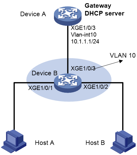
Network configuration
As shown in Figure 5, configure Device B to perform user validity check based on 802.1X security entries for connected hosts.
Procedure
1. Add all interfaces on Device B to VLAN 10, and specify the IP address of VLAN-interface 10 on Device A. (Details not shown.)
2. Configure the DHCP server on Device A, and configure DHCP address pool 0.
<DeviceA> system-view
[DeviceA] dhcp enable
[DeviceA] dhcp server ip-pool 0
[DeviceA-dhcp-pool-0] network 10.1.1.0 mask 255.255.255.0
3. Configure Host A and Host B as 802.1X clients and configure them to upload IP addresses for ARP attack detection. (Details not shown.)
4. Configure Device B:
# Enable 802.1X.
<DeviceB> system-view
[DeviceB] dot1x
[DeviceB] interface ten-gigabitethernet 1/0/1
[DeviceB-Ten-GigabitEthernet1/0/1] dot1x
[DeviceB-Ten-GigabitEthernet1/0/1] quit
[DeviceB] interface ten-gigabitethernet 1/0/2
[DeviceB-Ten-GigabitEthernet1/0/2] dot1x
[DeviceB-Ten-GigabitEthernet1/0/2] quit
# Add a local user test.
[DeviceB] local-user test class network
[DeviceB-luser-network-test] service-type lan-access
[DeviceB-luser-network-test] password simple test
[DeviceB-luser-network-test] quit
# Enable ARP attack detection for VLAN 10 to check user validity based on 802.1X entries.
[DeviceB] vlan 10
[DeviceB-vlan10] arp detection enable
# Configure the upstream interface as an ARP trusted interface. By default, an interface is an untrusted interface.
[DeviceB-vlan10] interface ten-gigabitethernet 1/0/3
[DeviceB-Ten-GigabitEthernet1/0/3] arp detection trust
[DeviceB-Ten-GigabitEthernet1/0/3] quit
Verifying the configuration
# Verify that ARP packets received on interfaces Ten-GigabitEthernet 1/0/1 and Ten-GigabitEthernet 1/0/2 are checked against 802.1X entries.
Example: Configuring user validity check and ARP packet validity check
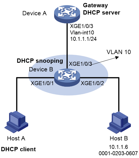
Network configuration
As shown in Figure 6, configure Device B to perform ARP packet validity check and user validity check based on static IP source guard bindings and DHCP snooping entries for connected hosts.

Procedure
1. Add all interfaces on Device B to VLAN 10, and specify the IP address of VLAN-interface 10 on Device A. (Details not shown.)
2. Configure the DHCP server on Device A, and configure DHCP address pool 0.
<DeviceA> system-view
[DeviceA] dhcp enable
[DeviceA] dhcp server ip-pool 0
[DeviceA-dhcp-pool-0] network 10.1.1.0 mask 255.255.255.0
3. Configure Host A (DHCP client) and Host B. (Details not shown.)
4. Configure Device B:
# Enable DHCP snooping.
<DeviceB> system-view
[DeviceB] dhcp snooping enable
[DeviceB] interface ten-gigabitethernet 1/0/3
[DeviceB-Ten-GigabitEthernet1/0/3] dhcp snooping trust
[DeviceB-Ten-GigabitEthernet1/0/3] quit
# Enable recording of client information in DHCP snooping entries on Ten-GigabitEthernet 1/0/1.
[DeviceB] interface ten-gigabitethernet 1/0/1
[DeviceB-Ten-GigabitEthernet1/0/1] dhcp snooping binding record
[DeviceB-Ten-GigabitEthernet1/0/1] quit
# Enable ARP attack detection for VLAN 10.
[DeviceB] vlan 10
[DeviceB-vlan10] arp detection enable
# Configure the upstream interface as a trusted interface. By default, an interface is an untrusted interface.
[DeviceB-vlan10] interface ten-gigabitethernet 1/0/3
[DeviceB-Ten-GigabitEthernet1/0/3] arp detection trust
[DeviceB-Ten-GigabitEthernet1/0/3] quit
# Configure a static IP source guard binding entry on interface Ten-GigabitEthernet 1/0/2 for user validity check.
[DeviceB] interface ten-gigabitethernet 1/0/2
[DeviceB-Ten-GigabitEthernet1/0/2] ip source binding ip-address 10.1.1.6 mac-address 0001-0203-0607 vlan 10
[DeviceB-Ten-GigabitEthernet1/0/2] quit
# Enable ARP packet validity check by checking the MAC addresses and IP addresses of ARP packets.
[DeviceB] arp detection validate dst-mac ip src-mac
Verifying the configuration
# Verify that Device B first checks the validity of ARP packets received on Ten-GigabitEthernet 1/0/1 and Ten-GigabitEthernet 1/0/2. If the ARP packets are confirmed valid, Device B performs user validity check by using the static IP source guard bindings and finally DHCP snooping entries.
Example: Configuring ARP restricted forwarding
Network configuration
As shown in Figure 7, configure ARP restricted forwarding on Device B where ARP attack detection is configured. Port isolation configured on Device B can take effect for broadcast ARP requests.
Procedure
1. Configure VLAN 10, add interfaces to VLAN 10, and specify the IP address of VLAN-interface 10 on Device A. (Details not shown.)
2. Configure the DHCP server on Device A, and configure DHCP address pool 0.
<DeviceA> system-view
[DeviceA] dhcp enable
[DeviceA] dhcp server ip-pool 0
[DeviceA-dhcp-pool-0] network 10.1.1.0 mask 255.255.255.0
3. Configure Host A (DHCP client) and Host B. (Details not shown.)
4. Configure Device B:
# Enable DHCP snooping, and configure Ten-GigabitEthernet 1/0/3 as a DHCP trusted interface.
<DeviceB> system-view
[DeviceB] dhcp snooping enable
[DeviceB] interface ten-gigabitethernet 1/0/3
[DeviceB-Ten-GigabitEthernet1/0/3] dhcp snooping trust
[DeviceB-Ten-GigabitEthernet1/0/3] quit
# Enable ARP attack detection for user validity check.
[DeviceB] vlan 10
[DeviceB-vlan10] arp detection enable
# Configure Ten-GigabitEthernet 1/0/3 as an ARP trusted interface.
[DeviceB-vlan10] interface ten-gigabitethernet 1/0/3
[DeviceB-Ten-GigabitEthernet1/0/3] arp detection trust
[DeviceB-Ten-GigabitEthernet1/0/3] quit
# Configure a static IP source guard entry on interface Ten-GigabitEthernet 1/0/2.
[DeviceB] interface ten-gigabitethernet 1/0/2
[DeviceB-Ten-GigabitEthernet1/0/2] ip source binding ip-address 10.1.1.6 mac-address 0001-0203-0607 vlan 10
[DeviceB-Ten-GigabitEthernet1/0/2] quit
# Enable ARP packet validity check by checking the MAC addresses and IP addresses of ARP packets.
[DeviceB] arp detection validate dst-mac ip src-mac
# Configure port isolation.
[DeviceB] port-isolate group 1
[DeviceB] interface ten-gigabitethernet 1/0/1
[DeviceB-Ten-GigabitEthernet1/0/1] port-isolate enable group 1
[DeviceB-Ten-GigabitEthernet1/0/1] quit
[DeviceB] interface ten-gigabitethernet 1/0/2
[DeviceB-Ten-GigabitEthernet1/0/2] port-isolate enable group 1
[DeviceB-Ten-GigabitEthernet1/0/2] quit
After the configurations are completed, Device B first checks the validity of ARP packets received on Ten-GigabitEthernet 1/0/1 and Ten-GigabitEthernet 1/0/2. If the ARP packets are confirmed valid, Device B performs user validity check by using the static IP source guard bindings and finally DHCP snooping entries. However, ARP broadcast requests sent from Host A can pass the check on Device B and reach Host B. Port isolation fails.
# Enable ARP restricted forwarding.
[DeviceB] vlan 10
[DeviceB-vlan10] arp restricted-forwarding enable
[DeviceB-vlan10] quit
Verifying the configuration
# Verify that Device B forwards ARP broadcast requests from Host A to Device A through the trusted interface Ten-GigabitEthernet 1/0/3. Host B cannot receive such packets. Port isolation operates correctly.
Configuring ARP scanning and fixed ARP
About this task
ARP scanning is typically used together with the fixed ARP feature in small-scale and stable networks.
ARP scanning automatically creates ARP entries for devices in an address range. The device performs ARP scanning in the following steps:
1. Sends ARP requests for each IP address in the address range.
2. Obtains their MAC addresses through received ARP replies.
3. Creates dynamic ARP entries.
You can manually trigger ARP scanning or enable automatic ARP scanning. Automatic ARP scanning periodically sends ARP requests for all IP addresses in the range at the specified rate.
Fixed ARP converts existing dynamic ARP entries (including those generated through ARP scanning) to static ARP entries. These static ARP entries are of the same attributes as the ARP entries that are manually configured. This feature prevents ARP entries from being modified by attackers.
You can set the ARP packet sending rate if the scanning range has a large number of IP addresses. This setting can avoid high CPU usage and heavy network load caused by a burst of ARP traffic.
Restrictions and guidelines
IP addresses in existing ARP entries are not scanned.
Due to the limit on the total number of static ARP entries, some dynamic ARP entries might fail the conversion.
Automatic ARP scan is supported only in R6515P06 and later. If you trigger ARP scanning and enable automatic ARP scanning, both of them take effect. As a best practice, use automatic ARP scanning only on networks where users come online and go offline frequently.
The arp fixup command is a one-time operation. You can use this command again to convert the dynamic ARP entries learned later to static.
To delete a static ARP entry converted from a dynamic one, use the undo arp ip-address [ vpn-instance-name ] command. You can also use the reset arp all command to delete all ARP entries or the reset arp static command to delete all static ARP entries.
Triggering an ARP scanning
1. Enter system view.
system-view
2. Enter interface view.
interface interface-type interface-number
3. Trigger an ARP scanning.
arp scan [ start-ip-address to end-ip-address ] [ send-rate { ppm ppm | pps } ]
|
|
CAUTION: ARP scanning will take some time. To stop an ongoing scan, press Ctrl + C. Dynamic ARP entries are created based on ARP replies received before the scan is terminated. |
Configuring automatic ARP scanning
1. Enter system view.
system-view
2. Set the ARP packet sending rate for automatic ARP scanning.
arp scan auto send-rate { ppm ppm | pps pps }
By default, the device sends ARP packets at the rate of 48 pps during automatic ARP scanning.
3. Enter interface view.
interface interface-type interface-number
4. Enable automatic ARP scanning.
arp scan auto enable [start-ip-address to end-ip-address]
By default, automatic ARP scanning is disabled.
Configuring fixed ARP
1. Enter system view.
system-view
2. Convert existing dynamic ARP entries to static ARP entries.
arp fixup
Configuring ARP gateway protection
About ARP gateway protection
Configure this feature on interfaces not connected with a gateway to prevent gateway spoofing attacks.
When such an interface receives an ARP packet, it checks whether the sender IP address in the packet is consistent with that of any protected gateway. If yes, it discards the packet. If not, it handles the packet correctly.
Restrictions and guidelines
You can enable ARP gateway protection for a maximum of eight gateways on an interface.
Do not configure both the arp filter source and arp filter binding commands on an interface.
If ARP gateway protection works with ARP attack detection, MFF, and ARP snooping, ARP gateway protection applies first.
Procedure
1. Enter system view.
system-view
2. Enter interface view.
interface interface-type interface-number
Supported interface types include Layer 2 Ethernet interface and Layer 2 aggregate interface.
3. Enable ARP gateway protection for the specified gateway.
arp filter source ip-address
By default, ARP gateway protection is disabled.
Example: Configuring ARP gateway protection
Network configuration
As shown in Figure 8, Host B launches gateway spoofing attacks to Device B. As a result, traffic that Device B intends to send to Device A is sent to Host B.
Configure Device B to block such attacks.
Procedure
# Configure ARP gateway protection on Device B.
<DeviceB> system-view
[DeviceB] interface ten-gigabitethernet 1/0/1
[DeviceB-Ten-GigabitEthernet1/0/1] arp filter source 10.1.1.1
[DeviceB-Ten-GigabitEthernet1/0/1] quit
[DeviceB] interface ten-gigabitethernet 1/0/2
[DeviceB-Ten-GigabitEthernet1/0/2] arp filter source 10.1.1.1
Verifying the configuration
# Verify that Ten-GigabitEthernet 1/0/1 and Ten-GigabitEthernet 1/0/2 discard the incoming ARP packets whose sender IP address is the IP address of the gateway.
Configuring ARP filtering
ARP filtering
The ARP filtering feature can prevent gateway spoofing and user spoofing attacks.
An interface enabled with this feature checks the sender IP and MAC addresses in a received ARP packet against permitted entries. If a match is found, the packet is handled correctly. If not, the packet is discarded.
Restrictions and guidelines
You can configure a maximum of eight permitted entries on an interface.
Do not configure both the arp filter source and arp filter binding commands on an interface.
If ARP filtering works with ARP attack detection, MFF, and ARP snooping, ARP filtering applies first.
Procedure
1. Enter system view.
system-view
2. Enter interface view.
interface interface-type interface-number
Supported interface types include Ethernet interface and Layer 2 aggregate interface.
3. Enable ARP filtering and configure a permitted entry.
arp filter binding ip-address mac-address
By default, ARP filtering is disabled.
Example: Configuring ARP filtering
Network configuration
As shown in Figure 9, the IP and MAC addresses of Host A are 10.1.1.2 and 000f-e349-1233, respectively. The IP and MAC addresses of Host B are 10.1.1.3 and 000f-e349-1234, respectively.
Configure ARP filtering on Ten-GigabitEthernet 1/0/1 and Ten-GigabitEthernet 1/0/2 of Device B to permit ARP packets from only Host A and Host B.

Procedure
# Configure ARP filtering on Device B.
<DeviceB> system-view
[DeviceB] interface ten-gigabitethernet 1/0/1
[DeviceB-Ten-GigabitEthernet1/0/1] arp filter binding 10.1.1.2 000f-e349-1233
[DeviceB-Ten-GigabitEthernet1/0/1] quit
[DeviceB] interface ten-gigabitethernet 1/0/2
[DeviceB-Ten-GigabitEthernet1/0/2] arp filter binding 10.1.1.3 000f-e349-1234
Verifying the configuration
# Verify that Ten-GigabitEthernet 1/0/1 permits ARP packets from Host A and discards other ARP packets.
# Verify that Ten-GigabitEthernet 1/0/2 permits ARP packets from Host B and discards other ARP packets.
Configuring ARP sender IP address checking
About ARP sender IP address checking
This feature allows a gateway to check the sender IP address of an ARP packet in a VLAN before ARP learning. If the sender IP address is within the allowed IP address range, the gateway continues ARP learning. If the sender IP address is out of the range, the gateway determines the ARP packet as an attack packet and discards it.
Restrictions and guidelines
If the VLAN is a sub-VLAN and is associated with a super VLAN, configure this checking feature only in the sub-VLAN.
If Layer 3 communication is configured between the secondary VLANs associated with a primary VLAN, configure this feature in the primary VLAN. If Layer 3 communication is not configured between the secondary VLANs associated with a primary VLAN, configure this feature in the intended VLAN.
Procedure
1. Enter system view.
system-view
2. Enter VLAN view.
vlan vlan-id
3. Enable the ARP sender IP address checking feature and specify the IP address range.
arp sender-ip-range start-ip-address end-ip-address
By default, the ARP sender IP address checking feature is disabled.
Example: Configuring ARP sender IP address checking
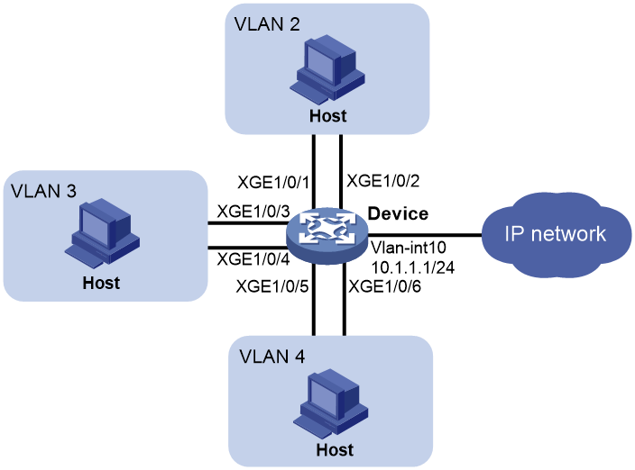
Network configuration
As shown in Figure 10, perform the following tasks:
· Create a super VLAN and associate it with VLANs 2, 3, and 4. VLANs 2, 3, and 4 are isolated at Layer 2 but interoperable at Layer 3. All hosts in VLANs 2, 3, and 4 use the gateway IP address 10.1.1.1/24 for Layer 3 communication.
· Configure the ARP sender IP address checking feature in VLAN 2 and specify the sender IP address range 10.1.1.1 to 10.1.1.10.
Procedure
# Create VLAN 10.
<Device> system-view
[Device] vlan 10
[Device-vlan10] quit
# Create VLAN-interface 10, and assign IP address 10.1.1.1/24 to it.
[Device] interface vlan-interface 10
[Device-Vlan-interface10] ip address 10.1.1.1 255.255.255.0
[Device] quit
# Create VLAN 2, and assign Ten-GigabitEthernet 1/0/1 and Ten-GigabitEthernet 1/0/2 to the VLAN.
[Device] vlan 2
[Device-vlan2] port ten-gigabitethernet 1/0/1 ten-gigabitethernet 1/0/2
[Device-vlan2] quit
# Create VLAN 3, and assign Ten-GigabitEthernet 1/0/3 and Ten-GigabitEthernet 1/0/4 to the VLAN.
[Device] vlan 3
[Device-vlan3] port ten-gigabitethernet 1/0/3 ten-gigabitethernet 1/0/4
[Device-vlan3] quit
# Create VLAN 4, and assign Ten-GigabitEthernet 1/0/5 and Ten-GigabitEthernet 1/0/6 to the VLAN.
[Device] vlan 4
[Device-vlan4] port ten-gigabitethernet 1/0/5 ten-gigabitethernet 1/0/6
[Device-vlan4] quit
# Configure VLAN 10 as a super VLAN, and associate sub-VLANs 2, 3, and 4 with the super VLAN.
[Device] vlan 10
[Device-vlan10] supervlan
[Device-vlan10] subvlan 2 3 4
[Device-vlan10] quit
# Enable the ARP sender IP address checking feature in VLAN 2 and specify the IP address range 10.1.1.1 to 10.1.1.10.
[Device] vlan 2
[Device-vlan2] arp sender-ip-range 10.1.1.1 10.1.1.10
Verifying the configuration
# Verify that the device accepts only ARP packets whose sender IP addresses are within the specified address range 10.1.1.1 to 10.1.1.10. The device discards the ARP packets with the sender IP addresses that are out of the range.
