- Table of Contents
-
- H3C MSR Routers Configuration Examples-6W100
- 00-Preface
- 01-H3C MSR Routers RBAC Configuration Examples (Comware V7)
- 02-H3C MSR Routers Ethernet Link Aggregation Configuration Examples (Comware V7)
- 03-H3C MSR Routers Port Isolation Configuration Examples (Comware V7)
- 04-H3C MSR Routers VLAN Configuration Examples (Comware V7)
- 05-H3C MSR Routers QinQ Configuration Examples (Comware V7)
- 06-H3C MSR Routers PPP Configuration Examples (Comware V7)
- 07-H3C MSR Routers OSPF Configuration Examples (Comware V7)
- 08-H3C MSR Routers OSPFv3 Configuration Examples (Comware V7)
- 09-H3C MSR Routers IPv6 IS-IS Configuration Examples (Comware V7)
- 10-H3C MSR Routers BGP Configuration Examples (Comware V7)
- Related Documents
-
| Title | Size | Download |
|---|---|---|
| 04-H3C MSR Routers VLAN Configuration Examples (Comware V7) | 65.79 KB |
H3C MSR Routers VLAN Configuration Examples (Comware V7)
Copyright © 2017 New H3C Technologies Co., Ltd. All rights reserved.
No part of this manual may be reproduced or transmitted in any form or by any means without prior written consent of New H3C Technologies Co., Ltd.
Except for the trademarks of New H3C Technologies Co., Ltd., any trademarks that may be mentioned in this document are the property of their respective owners.
The information in this document is subject to change without notice.
Introduction
This document provides port-based VLAN configuration examples.
Prerequisites
This document applies to Comware V7-based MSR routers. Procedures and information in the examples might be slightly different depending on the software or hardware version of the router.
The configuration examples in this document were created and verified in a lab environment, and all the devices were started with the factory default configuration. When you are working on a live network, make sure you understand the potential impact of every command on your network.
This document assumes that you have basic knowledge of H3C VLANs.
General configuration restrictions and guidelines
This feature is supported only on the following hardware:
· Interface modules SIC-4GSW, DSIC-9FSW, DSIC-9FSW-PoE, HMIM-24GSW, HMIM-24GSW-PoE, and HMIM-8GSW.
· The fixed Layer 2 ports on the MSR3600-28, and MSR3600-51 routers.
Example: Configuring port-based VLANs
Network requirements
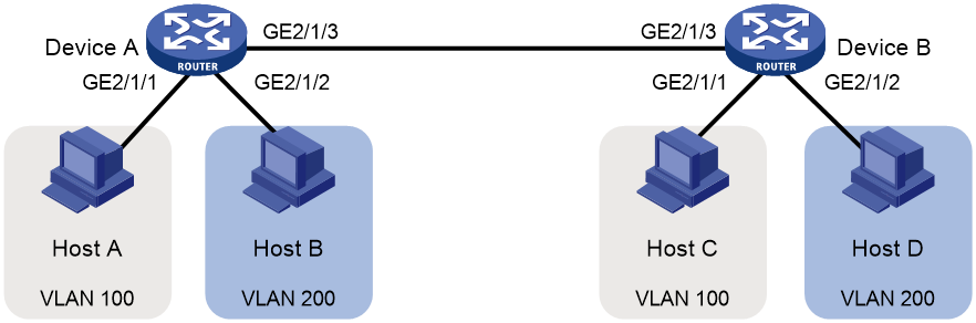
As shown in Figure 1:
· Host A and Host C belong to Department A. VLAN 100 is assigned to Department A.
· Host B and Host D belong to Department B. VLAN 200 is assigned to Department B.
Configure port-based VLANs so that hosts only in the same department can communicate with each other.
Software version used
This configuration example was created and verified on R0106.
Configuration procedures
# Configure the ports GigabitEthernet 2/1/1 through GigabitEthernet 2/1/3 to operate in bridge mode.
[DeviceA] interface range gigabitethernet 2/1/1 to gigabitethernet 2/1/3
[DeviceA-if-range] port link-mode bridge
[DeviceA-if-range] quit
# Create VLAN 100, and assign GigabitEthernet 2/1/1 to VLAN 100.
[DeviceA-vlan100] port gigabitethernet 2/1/1
[DeviceA-vlan100] quit
# Create VLAN 200, and assign GigabitEthernet 2/1/2 to VLAN 200.
[DeviceA-vlan200] port gigabitethernet 2/1/2
[DeviceA-vlan200] quit
# Configure GigabitEthernet 2/1/3 as a trunk port, and assign it to VLANs 100 and 200.
[DeviceA] interface gigabitethernet 2/1/3
[DeviceA-GigabitEthernet2/1/3] port link-type trunk
[DeviceA-GigabitEthernet2/1/3] port trunk permit vlan 100 200
2. Configure Device B in the same way Device A is configured. (Details not shown.)
3. Configure hosts:
a. Configure Host A and Host C to be on the same IP subnet. For example, 192.168.100.0/24.
b. Configure Host B and Host D to be on the same IP subnet. For example, 192.168.200.0/24.
Verifying the configuration
# Verify that Host B and Host D can ping each other, but they both fail to ping Host A or Host C. (Details not shown.)
# Display information about VLAN 100 on Device A.
[DeviceA-GigabitEthernet2/1/3] display vlan 100
VLAN ID: 100
VLAN type: Static
Route interface: Not configured
Description: VLAN 0100
Name: VLAN 0100
Tagged ports:
GigabitEthernet2/1/3
Untagged ports:
GigabitEthernet2/1/1
The output shows that GigabitEthernet 2/1/3 and GigabitEthernet 2/1/1 permit packets from VLAN 100 to pass through.
# Display information about VLAN 200 on Device A.
[DeviceA-GigabitEthernet2/1/3] display vlan 200
VLAN ID: 200
VLAN type: Static
Route interface: Not configured
Description: VLAN 0200
Name: VLAN 0200
Tagged ports:
GigabitEthernet2/1/3
Untagged ports:
GigabitEthernet2/1/2
The output shows that GigabitEthernet 2/1/3 and GigabitEthernet 2/1/2 permit packets from VLAN 200 to pass through.
Configuration files
Configuration files on both Device B and Device A are the same. The following configuration files use Device A as an example.
#
vlan 100
#
vlan 200
#
interface GigabitEthernet2/1/1
port link-mode bridge
port access vlan 100
#
interface GigabitEthernet2/1/2
port link-mode bridge
port access vlan 200
#
interface GigabitEthernet2/1/3
port link-mode bridge
port link-type trunk
port trunk permit vlan 1 100 200
#
Related documentation
· H3C MSR Series Routers Layer 2—LAN Switching Command Reference(V7)
· H3C MSR Series Routers Layer 2—LAN Switching Configuration Guide(V7)
