- Table of Contents
-
- 16-BRAS Services Configuration Guide
- 00-Preface
- 01-BRAS services overview
- 02-AAA configuration
- 03-ANCP configuration
- 04-PPP configuration
- 05-ITA configuration
- 06-EDSG configuration
- 07-DHCP configuration
- 08-DHCPv6 configuration
- 09-User profile configuration
- 10-Connection limit configuration
- 11-L2TP configuration
- 12-PPPoE configuration
- 13-Portal configuration
- 14-IPoE configuration
- Related Documents
-
| Title | Size | Download |
|---|---|---|
| 14-IPoE configuration | 2.66 MB |
IPoE access procedure by using bind authentication
IPoE access procedure by using Web authentication
Support for EAP authentication
Restrictions and guidelines: IPoE configuration
IPoE bind authentication user tasks at a glance
IPoE Web authentication individual user tasks at a glance
Configuring the remote portal authentication server
Specifying the HTTPS redirect listening port number
Obtaining user access information from ARP or ND entries
Enabling IPoE and setting the IPoE access mode
Configuring the authentication method
Configuring dynamic individual users
Dynamic individual user tasks at a glance
Configuring a dynamic individual session initiation method
Configuring authentication user naming conventions for dynamic individual users
Configuring passwords for dynamic individual users
Configuring ISP domains for dynamic individual users
Setting the dynamic individual session limit
Configuring trusted DHCP options for DHCP users
Configuring the parsing format for the circuit ID and remote ID in the DHCP option
Configuring trusted ISP domains for DHCP users
Configuring domain name generation rules for dynamic IPoE DHCP users
Allowing abnormally logged out DHCP users to come online again through packet initiation
Configuring trusted source IP addresses for unclassified-IP users
Allowing dynamic users to access in loose mode
Configuring static individual users
Static individual user tasks at a glance
Configuring a static individual session initiation method
Configuring static individual sessions
Configuring authentication user naming conventions for static individual users
Configuring passwords for static individual users
Configuring ISP domains for static individual users
Configuring an interface-leased user
Configuring subnet-leased users
Configuring an L2VPN-leased user
Configuring ISP domains for leased users
Configuring Web authentication advanced features
Web authentication advanced feature tasks at a glance
Configuring an ISP domain for Web authentication individual users
Configuring HTTP packet fast reply
Configuring an SSL server policy for HTTPS redirection
Configuring the captive-bypass feature
Configuring Web authentication fail-permit
Configuring IPoE quick Web authentication
Configuring MAC-trigger authentication
Configuring transparent MAC authentication
Setting the maximum number of individual sessions and leased subuser sessions on an interface
Configuring service-specific ISP domains
Configuring the quiet feature for users
Configuring online detection for IPoE users
Configuring the interface-down policy for IPoE users on an interface
Configuring NAS-Port-Type for an interface
Configuring NAS-Port-ID formats
Configuring NAS-Port-ID binding for IPoE access users
Enabling IPoE access-out authentication
Setting the traffic statistics update timer for IPoE sessions
Configuring IPoE logging and service maintenance
Enabling logging for IPoE users
Configuring the per-slot user count trap feature
Configuring service tracing objects
Enabling roaming for IPoE individual users
Setting the response delay time for IPoE users
Forbidding IPoE users from coming online
Display and maintenance commands for IPoE
Example: Configuring unclassified-IP packet initiation
Example: Configuring DHCPv4 packet initiation (assigning a DHCP relay address pool)
Example: Configuring DHCPv4 packet initiation (assigning a DHCP address pool group)
Example: Configuring DHCPv6 packet initiation
Example: Configuring a dual-stack user
Example: Configuring IPv6 ND RS packet initiation (AAA-authorized prefix)
Example: Configuring IPv6 ND RS packet initiation (ND prefix pool-authorized prefix)
Example: Configuring ARP packet initiation
Example: Configuring NS/NA packet initiation
Example: Configuring subnet-leased users
Example: Configuring an interface-leased user
Example: Configuring an L2VPN-leased user
Example: Configuring a VPN DHCP user
Example: Configuring online detection
Example: Configuring IPoE common Web authentication for static users
Example: Configuring IPoE common Web authentication for DHCPv4 users
Example: Configuring IPoE common Web authentication for DHCPv6 users
Example: Configuring IPoE common Web authentication for IPoE ND RS users
Example: Configuring IPoE common Web authentication for dual-stack users
Example: Configuring IPoE Layer 2 transparent MAC-trigger authentication
Example: Configuring IPoE Layer 3 transparent MAC-trigger authentication
Example: Configuring IPoE Layer 2 transparent MAC authentication
Example: Configuring IPoE Layer 3 transparent MAC authentication
Example: Configuring IPoE transparent MAC authentication for dual-stack users
Example: Configuring IPoE Web authentication with EAP
Example: Configuring a roaming user
DHCP clients failed to come online
Configuring IPoE
About IPoE
IP over Ethernet (IPoE) enables a Broadband Remote Access Server (BRAS) to connect and authenticate users over IPoE connections.
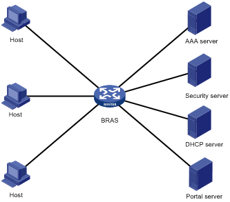
As shown in Figure 1, a BRAS connects hosts over IPoE connections, and provides AAA, security, DHCP, and portal services for the hosts. The host can be a browser running HTTP or HTTPS or a cellphone running the H3C iNode client.
Figure 1 IPoE network diagram
IPoE access modes
IPoE supports Layer 2 and Layer 3 access modes.
· Layer 2 access mode—Hosts directly access the BRAS. The hosts connect to the BRAS directly or through Layer 2 devices. The BRAS uses MAC addresses to identify the hosts.
· Layer 3 access mode—Hosts use routing to access the BRAS. The hosts connect to the BRAS directly or through Layer 3 devices. On a Layer 3 device between the hosts and BRAS, the source MAC address of packets received by the BRAS is the MAC address of the Layer 3 device. Therefore, the BRAS uses IP addresses or VLAN IDs to identify hosts.
IPoE user types
IPoE sessions can be initiated by IP, ARP, NS, NA, ND RS, or DHCP packets. Depending on whether an IPoE user has independent service attributes, IPoE users include individual users and leased users.
Individual users
Individual users use independent IPoE services. The BRAS authenticates, authorizes, and accounts individual users based on user location and packet information. Individual users include dynamic and static individual users.
· Dynamic individual users
IPoE defines the following dynamic individual users:
? DHCP user—Sends DHCP packets to initiate IPoE sessions and obtains an IP address from the DHCP server.
? IPv6 ND RS user—Sends IPv6 ND RS packets to initiate IPoE sessions and obtains an IP address from the BRAS.
? Unclassified-IP user—Sends packets other than DHCP and IPv6 ND RS packets to initiate IPoE sessions.
· Static individual users
Static individual users initiate IPoE sessions by sending IP, ARP, NS, or NA packets. If an IP packet matches a manually configured IPoE session, the BRAS authenticates the user and establishes an IPoE session.
|
|
NOTE: A DHCP user is abnormally logged out if the IPoE session of the user is deleted for a reason except the user actively releases its IP address. With the function of allowing abnormally logged out DHCP users to come online again enabled, when the device receives IP or ARP packets from the user, the device can restore the IPoE session for the user. The restored IPoE session is a DHCP session. For more information about re-logging in abnormally logged out DHCP users, see "Allowing abnormally logged out DHCP users to come online again through packet initiation." |
Leased users
Leased users include the following types:
· Interface-leased user—Represents hosts that rent the same interface.
· Subnet-leased user—Represents hosts that rent a subnet of an interface.
· L2VPN-leased user—Represents hosts that rent the same interface on an L2VPN network.
The BRAS automatically uses the credentials configured for a leased user to perform authentication. Users are not required to send IP packets to trigger authentication.
IPoE session
An IPoE session represents all network connections of one IPoE client or a group of IPoE clients. An IPoE session can be identified by the IP packet characteristics or access location of clients. An IPoE session records the identification information, authentication status, authorization attributes, and DHCP address assignment information of IPoE clients.
Depending on the IPoE user types, IPoE sessions include individual sessions and leased sessions. .
Individual sessions
Depending on how a session is initiated, IPoE individual sessions include IPoE dynamic individual sessions and IPoE static individual sessions.
· IPoE dynamic individual session
IPoE sessions established for dynamic individual users are IPoE dynamic individual sessions.
The BRAS deletes a dynamic individual session in one of the following cases:
? The AAA-authorized session duration expires.
? The AAA server logs out the user.
? The user traffic is less than the AAA-authorized traffic during the idle-timeout time.
? The BRAS cannot detect the user after the number of detection attempts reaches the maximum.
- For a single-stack user, the session is deleted when the number of detection attempts reaches the maximum.
- For a dual-stack user, the session is deleted when the number of detection attempts reaches the maximum for both stacks.
? The IP address lease expires for IPoE sessions initiated by DHCP packets.
- For a single-stack user, the session is deleted when the IP address lease expires.
- For a dual-stack user, the session is deleted when the IP address leases of both stacks expire.
? The IPoE session is restarted.
? The access interface goes down.
· IPoE static individual session
An IPoE static individual session represents all network connections of an IPoE client with the specified IP address. Typically, IPoE static individual sessions provide stable access services for clients with known IP addresses.
IPoE static individual sessions include interface-level static individual sessions and global static individual sessions.
? Interface-level static individual sessions—The BRAS creates a static individual session based on configured information after you enable IPoE on an interface in up state. The BRAS initiates user authentication based on the configured username and password upon receiving IP, ARP, NS, or NA packets from users.
? Global static individual sessions—On an IPoE-enabled interface in up state, the BRAS initiates authentication based on the configured username and password upon receiving IP, ARP, NS, or NA packets from users. The BRAS creates a global static individual session only when the authentication succeeds.
IPoE leased sessions
IPoE leased sessions are IPoE sessions established for IPoE leased users. IPoE leased sessions include the following types:
· Interface-leased session—Represents network connections of all IPoE clients on an interface.
· Subnet-leased session—Represents network connections of all IPoE clients in a subnet of an interface.
· L2VPN-leased session—Represents network connections of all IPoE client on an interface.
For leased users, the BRAS creates a leased session based on configured information after you enable IPoE on an interface in up state. The BRAS initiates user authentication based on the configured username and password.
IPoE addressing
IPoE addressing varies with user types.
A DHCP user obtains IP addresses in the following sequence:
1. Obtains an IP address from the AAA-authorized IP address pool.
2. Obtains an IP address from the IP address pool configured in the ISP domain if the AAA server does not authorize any IP address pools.
3. Obtains an IP address in the same network segment as the interface IP address if no IP address pool is configured in the ISP domain.
After an IPv6 ND RS user passes authentication, the user can obtain an IPv6 prefix and generate an IPv6 address based on the prefix. IPv6 prefixes include the following types in descending order of priority: AAA-authorized IPv6 prefix, prefix in the AAA-authorized ND prefix pool, RA prefix configured on an interface, and IPv6 global unicast address prefix configured on an interface.
When an ND prefix pool is used to assign prefixes to users, follow these restrictions and guidelines:
· This methodis unavailable in .
· On a user access interface, you must configure a link-local address rather than an IPv6 global unicast address as the user gateway.
Other users use static IP addresses or obtain IP addresses from the DHCP server without using IPoE.
IPoE access procedure by using bind authentication
IPoE access by using bind authentication includes the following steps:
1. The BRAS initiates authentication.
The BRAS obtains information from user packets or IPoE sessions statically configured, and sends authentication requests.
2. The AAA server authenticates users.
The AAA server completes user authentication and sends the result to the BRAS. The security server, if configured, completes security authorization and sends the result to the BRAS.
3. (Optional.) DHCP allocates IP addresses and IPoE allocates IPv6 prefixes.
The DHCP server assigns an IP address to a DHCP user and the IPoE assigns an IPv6 prefix to an IPv6 ND RS user.
4. The BRAS performs access control.
The BRAS permits the user to get online and performs access control and accounting based on the authorized result.
Access procedure for DHCP single-stack users
This section uses a DHCPv4 user as an example to illustrate the access procedure for DHCP single-stack users. The BRAS acts as a DHCP relay agent.
Figure 2 Access procedure for a DHCPv4 user
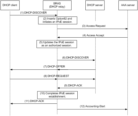
1. The DHCP client sends a DHCP-DISCOVER message to the BRAS.
2. The BRAS inserts Option 82 in the DHCP-DISCOVER message, and creates an IPoE session.
3. The BRAS sends the AAA server an access request that includes user information, such as the client ID and source MAC address.
4. The AAA server returns an Access-Accept packet that contains authorization information to the BRAS if the authentication succeeds. If the authentication fails, the AAA server returns an Access-Reject message.
5. The BRAS marks the IPoE session state as success and forwards the DHCP-DISCOVER message to the DHCP server if the authentication succeeds. If the authentication fails, the BRAS marks the session as failure and drops the DHCP-DISCOVER message.
6. The DHCP server sends a DHCP-OFFER message to the BRAS.
7. The BRAS forwards the DHCP-OFFER message to the DHCP client.
8. The DHCP client sends a DHCP-REQUEST message to the BRAS.
9. The BRAS forwards the DHCP-REQUEST message to the specified DHCP sever.
10. The DHCP server sends a DHCP-ACK message containing the assigned IP address to the BRAS.
11. The BRAS performs the following operations:
a. Obtains address information from the DHCP-ACK message.
b. Assigns a user profile.
c. Updates the IPoE session information.
d. Forwards the DHCP-ACK message to the client.
e. Marks the session state as online.
If the authentication fails, the BRAS marks the session as failure and drops the DHCP-DISCOVER message.
12. The DHCP client obtains configuration information from the DHCP-ACK message.
13. The BRAS sends the AAA server a message to start accounting.
Access procedure for DHCP dual-stack users
This section illustrates the access procedure for DHCP dual-stack users. The BRAS acts as a DHCP relay agent.
Figure 3 Access procedure for a DHCP dual-stack user
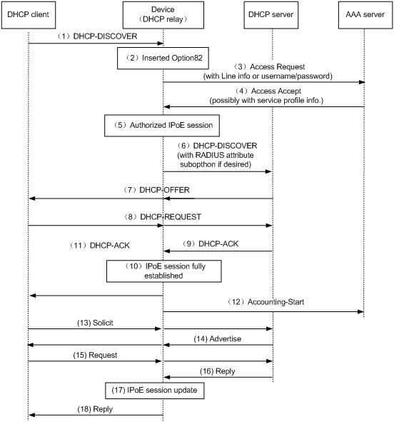
1. The DHCPv4 client sends a DHCP-DISCOVER message.
2. The DHCPv4 relay agent inserts Option 82 in the DHCP-DISCOVER message, and creates an IPoE session.
3. The relay agent sends the AAA server an access request including user information, such as the client ID and source MAC address in DHCPv4 packets.
4. The AAA server returns an Access-Accept packet that contains authorization information to the DHCPv4 relay agent if the authentication succeeds. If the authentication fails, the AAA server returns an Access-Reject message.
5. The DHCPv4 relay agent obtains the user authentication and authorization result, and updates the session status to success or failure.
6. The DHCPv4 relay agent forwards the DHCP-DISCOVER message to the DHCP server if the authentication succeeds. If the authentication fails, the DHCPv4 relay agent drops the DHCP-DISCOVER message.
7. The DHCPv4 server sends a DHCP-OFFER message to the DHCPv4 relay agent. The DHCPv4 relay agent forwards the DHCP-OFFER message to the DHCP client.
8. The DHCPv4 client sends a DHCP-REQUEST message to the DHCPv4 relay agent. The DHCPv4 relay agent forwards the DHCP-REQUEST message to the specified DHCP sever.
9. The DHCP server sends a DHCP-ACK message containing the assigned IP address to the DHCPv4 relay agent.
10. The DHCPv4 relay agent performs the following operations:
a. Obtains address information from the DHCP-ACK message.
b. Assigns a user profile.
c. Updates the IPoE session information.
d. Marks the session state as online.
11. The DHCPv4 relay agent forwards the DHCP-ACK message to the client. The DHCP client obtains configuration information from the DHCP-ACK message.
12. The DHCPv4 relay agent sends the AAA server a message to start accounting.
13. The DHCPv6 client sends a Solicit message. The DHCPv6 relay agent updates IPoE session information based on the Solicit message.
14. The DHCPv6 server responds with an Advertise message. Then, the DHCPv6 relay agent forwards the Advertise message to the DHCPv6 client.
15. The DHCPv6 client select a DHCPv6 server according to the Advertise message and sends a request. The DHCPv6 relay agent forwards the request to the DHCPv6 server.
16. The DHCPv6 server responds with a reply message.
17. The DHCPv6 relay agent parses the IPv6 address and other address parameters in the reply message, and updates the IPoE session.
18. The DHCPv6 relay agent forwards the reply message to the DHCPv6 client. The DHCPv6 client obtains the IPv6 address and related address parameters.
Access procedure for IPv6 ND RS users
This example uses a Layer 2 device as the BRAS.
Figure 4 Access procedure for IPv6 ND RS users
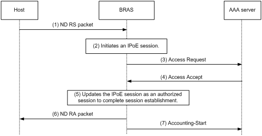
1. The host sends an IPv6 ND RS packet to the BRAS.
2. The BRAS initiates an IPoE session and sends the AAA server an access request that contains user information, such as the source MAC address.
3. The AAA server returns an Access-Accept packet that contains authorization information to the BRAS if the authentication succeeds. If the authentication fails, the AAA server returns an Access-Reject message.
4. The BRAS performs the following operations:
a. Generates an IPv6 address based on the host's MAC address and the IPv6 prefix.
b. Updates the IPoE session information.
c. Marks the session as success.
If the authentication fails, the BRAS marks the session as failure and drops the IPv6 ND RS packet.
5. The BRAS assigns a user profile and sends the host an IPv6 ND RA packet containing the IPv6 prefix.
6. The host generates an IPv6 address based on the received IPv6 prefix.
7. The BRAS sends the AAA server a message to start the service accounting.
Access procedure for unclassified-IP users
Figure 5 Access procedure for unclassified-IP users
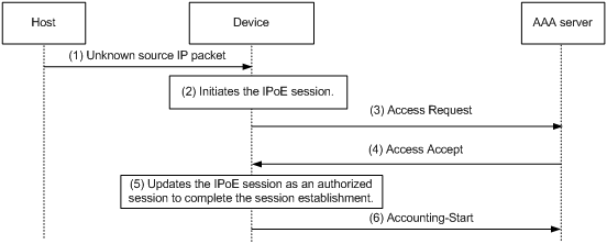
1. The host sends an IP packet to the BRAS.
2. The BRAS obtains user information from the IP packet, and compares the user information with existing IPoE sessions.
? If no match is found, the BRAS initiates an IPoE session for the user. (This section uses this case as an example.)
? If the information matches an authenticated session, the BRAS forwards the IP packet.
? If the information matches an unauthenticated session, the BRAS drops the IP packet.
3. The BRAS sends the AAA server an access request containing the obtained information, such as the source IP address or source MAC address.
4. The AAA server returns an Access-Accept packet that contains authorization information if the authentication succeeds. If the authentication fails, the AAA server returns an Access-Reject message.
5. The BRAS assigns a user profile and marks the IPoE session state as online.
6. The BRAS sends the AAA server a message to start the service accounting.
Access procedure for static and leased users
The access procedure for static users is the same as that for unclassified-IP users except in the following aspects:
· The IPoE static session is configured at the CLI.
· The IPoE static session can be initiated by IP, ARP, NS, or NA packets.
The access procedure for leased users is the same as that for unclassified-IP users except in the following aspects:
· The IPoE leased session is configured at the CLI.
· The IPoE leased session does not need to be initiated by packets. Users are not required to send IP packets to trigger authentication. The BRAS initiates user authentication based on the configured username and password.
IPoE access procedure by using Web authentication
IPoE Web authentication applies to DHCP users, IPv6 ND RS users, and static users. The authentication process includes two phases: preauthentication and Web authentication.
Preauthentication access procedure
The access procedure in the preauthentication phase is the same as the access procedure by using bind authentication for DHCP users and static users. For more information about the access procedure, see "Access procedure for DHCP single-stack users," "Access procedure for IPv6 ND RS users," and "Access procedure for static and leased users."
Web authentication access procedure
In the Web authentication phase, the authentication procedure is almost the same for users. This section uses a DHCPv4 user as an example to illustrate the access procedure by using Web authentication. The BRAS acts as a DHCP relay agent.
Figure 6 Web authentication access procedure
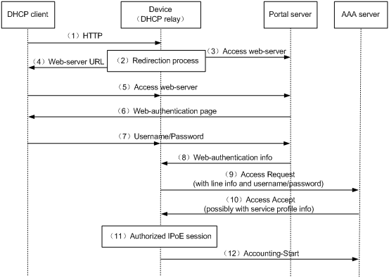
The user can perform Web authentication through the Web browser or the iNode client. This section uses the Web browser as an example.
1. The DHCP client initiates an HTTP/HTTPS GET message.
2. The BRAS checks the destination IP address of the HTTP/HTTPS GET message.
? If the message is destined for the portal Web server, the BRAS forwards the message to the portal Web server. The DHCP client directly accesses the Web authentication page of the portal Web server. .
? If the message is not destined for the portal Web server, the BRAS sends the message containing the Web server URL information to the DHCP client.
3. The DHCP client automatically accesses the redirected URL based on configured Web server URL information.
4. The portal Web server sends the Web authentication page to the DHCP client.
5. The user enters a username and password on the Web authentication page.
6. The portal server forwards the Web authentication information to the BRAS.
7. The BRAS sends the AAA server an access request based on the Web authentication information.
8. The AAA server returns to the BRAS one of the following results:
? An Access-Accept packet that contains authorization information if the authentication succeeds.
? An Access-Reject message if the authentication fails.
9. The BRAS performs one of the following operations based on the received result:
? Updates the IPoE session state as failed upon receiving an Access-Reject message.
? Updates the IPoE session state as authorized upon receiving an Access-Accept packet.
10. If the authentication succeeds, the BRAS sends the AAA server a message to start accounting.
|
|
NOTE: When the user performs Web authentication through the iNode client, the user can directly open the client authentication page and enter the authentication information. The remaining steps 6 through 10 are the same. |
IPoE quick Web authentication
In an IPoE Web environment, IPoE Web authentication supports quick authentication. With quick authentication, users that access the network frequently do not need to enter authentication information each time they come online in the Web authentication phase.
For valid users that access the network frequently, you can implement MAC-based quick authentication. It allows users to pass authentication without entering authentication information. MAC-based quick authentication is also called transparent authentication. Based on the location where the usernames, passwords, and MAC-to-account bindings of users are stored, transparent authentication includes the following types:
· Transparent MAC-trigger authentication—To use transparent MAC-trigger authentication, you must deploy a MAC binding server in the network. The MAC binding server records the MAC-to-account bindings of users for authentication.
· Transparent MAC authentication—To use transparent MAC authentication, you must deploy an AAA server that can bind the Web authentication information of users to MAC addresses of user endpoints for authentication.
With IPoE quick Web authentication configured, IPoE queries the MAC bindings for a user when receiving any IP packets of the user in the preauthentication domain. For a user that uses Web access for the first time, the authentication procedure includes the querying process.
Transparent MAC-trigger authentication procedure
|
|
IMPORTANT: · Transparent MAC-trigger authentication is only supported by IPv4 users. · Transparent MAC-trigger authentication supports only Web authentication that is triggered through the Web browser. |
1. The client initiates HTTP/HTTP requests after coming online in the preauthentication domain.
2. The BRAS checks the destination IP of the HTTP/HTTPS request.
3. If the message is destined for the portal Web server, the BRAS forwards the message to the portal Web server.
4. If the message is not destined for the portal Web server, the BRAS sends a binding query request to the portal server. The portal server returns the query result.
If the query result shows that the user has not been bound, the following operations are performed:
a. The BRAS redirects the subsequent HTTP/HTTPS requests to the Web authentication page of portal Web server. The BRAS sends HTTP/HTTPS messages containing the Web authentication page URL of the portal Web server to the client.
b. The client browser automatically accesses the Web authentication page of the portal Web server.
c. The portal Web server sends the Web authentication page contents to the client.
d. The user enters the username and password and click Log in to send the authentication information to the portal server.
If the query result shows that the user has been bound, the BRAS waits for the Web authentication information from the portal server.
5. The portal Web server sends the Web authentication information to the BRAS.
6. The BRAS sends the AAA server an access request based on the Web authentication information.
7. The AAA server returns to the BRAS one of the following results:
? An Access-Accept packet that contains the authorization information if the authentication succeeds.
? An Access-Reject message if the authentication fails.
8. The BRAS performs one of the following operations based on the received result:
? Updates the IPoE session state as failed upon receiving an Access-Reject message.
? Updates the IPoE session state as authorized upon receiving an Access-Accept packet.
9. If the authentication succeeds, the BRAS sends the AAA server a message to start accounting.
10. (Applicable only to users that perform Web authentication the first time.) After the user comes online, the BRAS notifies the portal server of the event. After receiving the notification, the portal server notifies the MAC binding server to add a MAC binding for the user.
When the user accesses the network the next time, the user can come online through quick authentication based on the queried MAC binding entry after the BRAS receives any IP packets of the user.
Transparent MAC authentication procedure
|
|
IMPORTANT: · Transparent MAC authentication supports only Web authentication that is triggered through the Web browser. |
The transparent MAC authentication procedure is as follows (take the first login as an example):
1. The client initiates HTTP/HTTP requests after coming online in the preauthentication domain.
2. The BRAS checks the destination IP of the HTTP/HTTPS request.
3. If the message is destined for the portal Web server, the BRAS forwards the message to the portal Web server.
4. If the message is not destined for the portal Web server, the BRAS uses the MAC address of the user as the username to send authentication requests to the AAA server. Because the user logs in for the first time, the AAA server fails to query the binding of the user based on the MAC address and returns authentication failure.
a. The BRAS redirects the subsequent HTTP/HTTPS requests to the Web authentication page of portal Web server.
b. The client browser automatically accesses the Web authentication page of the portal Web server.
c. The portal Web server sends the Web authentication page contents to the client.
d. The user enters the username and password and click Log in to send the authentication information to the portal server.
5. The portal Web server sends the Web authentication information to the BRAS.
6. The BRAS sends the AAA server an access request based on the Web authentication information.
7. The authentication succeeds. The AAA server returns to the BRAS an Access-Accept packet that contains the authorization information.
8. The BRAS updates the IPoE session state as authorized upon receiving an Access-Accept packet.
9. The authentication succeeds. The BRAS sends the AAA server a message to start accounting.
10. After the user comes online, the BRAS notifies the AAA server of the event. After receiving the notification, the AAA server adds a MAC binding for the user.
When the user accesses the network the next time, the BRAS uses the MAC address of the user as the username to send authentication requests to the AAA server after receiving any IP packets of the user. The AAA server can query the MAC binding for the user and returns authentication success. Then, the user can come online without entering the username and password.
Support for MPLS L3VPN
IPoE supports MPLS L3VPN. It uses AAA to authorize VPNs for users. Before you bind a VPN instance to an interface, you must delete existing IPoE sessions on the interface for the users to communicate in their authorized VPNs.
|
|
NOTE: · When an unclassified IPoE user comes online through an authorized VPN, you must configure a gateway IP address or use the gateway-list export-route command to advertise the gateway IP address in the DHCP address pool of the public network on the access interface. As a best practice, advertise the gateway IP address in the DHCP address pool of the public network. For more information about the gateway-list export-route command, see DHCP commands in BRAS Services Command Reference. · When a non-unclassified IPoE user comes online through an authorized VPN, you must configure a gateway IP address or enable proxy ARP by using the proxy-arp enable command on the access interface. As a best practice, enable proxy ARP. For more information, see proxy ARP configuration in Layer 3—IP Services Configuration Guide. · Leased users do not support AAA-authorized VPNs through ISP domains or AAA servers. For more information about VPN authorization through ISP domains, see "Configuring AAA." |
Support for ITA
ITA provides accounting and bandwidth solutions for users based on the destination addresses they access.
For more information about configuring ITA, see "Configuring AAA."
Support for EDSG
EDSG identifies the traffic of different services for a user and provides independent authentication, accounting, and rate limit for the traffic of each service.
After a user passes RADIUS authentication, the RADIUS server assigns EDSG service policies to the user. Then, the device uses the matching local EDSG service policies to provide service-based differentiated functions for the user.
For more information about configuring EDSG, see "Configuring EDSG service policies."
Support for EAP authentication
To use IPoE authentication that supports Extensible Authentication Protocol (EAP), make sure the portal authentication server and client are the H3C IMC portal server and the H3C iNode portal client, respectively.
Compared with username and password based authentication, digital certificate-based authentication provides higher security.
EAP supports several digital certificate-based authentication methods, for example, EAP-TLS. Working together with EAP, IPoE authentication can implement digital certificate-based user authentication.
Figure 7 IPoE support for EAP working flow
![]()
As shown in Figure 7, the authentication client and the portal authentication server exchange EAP authentication packets. The portal authentication server and the access device exchange portal authentication packets that carry the EAP-Message attributes. The access device and the RADIUS server exchange RADIUS packets that carry the EAP-Message attributes. The RADIUS server that supports the EAP server function processes the EAP packets encapsulated in the EAP-Message attributes, and provides the EAP authentication result.
The access device does not process but only transports EAP-Message attributes between the portal authentication server and the RADIUS server. The access device requires no additional configuration to support EAP authentication.
Restrictions and guidelines: IPoE configuration
For IPoE configuration to take effect on an interface, make sure the qos apply user-profile command has not been executed on the interface. For more information about the qos apply user-profile command, see user profiles commands in BRAS Services Command Reference.
This feature is available only when the system operates in standard mode. For more information about the system operating modes, see device management in Fundamentals Configuration Guide.
Only CSPEX (except CSPEX-1104-E)/CEPC cards support IPoE.
IPoE and IP source guard are mutually exclusive. For more information about IP source guard, see Security Configuration Guide.
IPoE supports the following interfaces:
· Layer 3 aggregate interfaces/subinterfaces.
· Layer 3 Ethernet interfaces/subinterface s.
· L3VE interfaces/subinterfaces.
In an IPv6 network, an endpoint might use a temporary IPv6 address for IPoE Web authentication, which will cause authentication failure. To avoid this problem, configure the ipv6 nd ra prefix { ipv6-prefix prefix-length | ipv6-prefix/prefix-length } no-advertise command on the interface through which the user comes online to prevent the endpoint from obtaining a temporary IPv6 address. The ipv6-prefix prefix-length | ipv6-prefix/prefix-length argument specifies the IPv6 prefix and prefix length of the network segment where the user resides. For information about temporary IPv6 addresses, see IPv6 basics in Layer 3—IP Services Configuration Guide.
When the device acts as the DHCP server that assigns IP addresses to IPoE users, you must execute the following commands:
· For a DHCPv4 address pool, execute the dhcp server forbidden-ip command or the forbidden-ip command to exclude the gateway IP address from dynamic allocation.
· For a DHCPv6 address pool, execute the ipv6 dhcp server forbidden-address command to exclude the gateway IPv6 address from dynamic allocation.
For more information, see DHCP commands and DHCPv6 commands in BRAS Services Command Reference.
If both the ISP domain and DHCP server are configured to assign the DNS servers to IPoE DHCP users, the following rules apply:
· If the IPoE device acts as a DHCP server, the DHCP users preferentially use the DNS servers assigned by the ISP domain.
· If the IPoE device acts as a DHCP relay agent, the DHCP users preferentially use the DNS servers assigned by the DHCP server.
In a DHCP relay agent network, the following rules apply:
· When IPoE operates in Layer 3 access mode and the BRAS acts as a DHCP server, for DHCP users to come online properly, do not configure the ip subscriber initiator arp enable command on the access interface.
· For a DHCPv4 relay agent, you must perform the following tasks:
? Use the dhcp relay client-information record command to enable recording client information in relay entries.
? Use the undo dhcp relay client-information refresh enable command to disable the DHCP relay agent from periodically refreshing dynamic relay entries.
? Use the dhcp select relay proxy command on the DHCP relay agent interface to enable DHCP server proxy on the relay agent.
· For a DHCPv6 relay agent, you must use the ipv6 dhcp relay client-information record command to enable recording client information in DHCPv6 relay entries.
In an IPoE application, the advertisement push function takes effect only on HTTP packets using port number 80 and HTTPS packets using port number 443.
IPoE tasks at a glance
After you enable IPoE and set the IPoE access mode, you can configure different types of IPoE users based on the network requirements.
IPoE bind authentication user tasks at a glance
To configure bind authentication users, perform the following tasks:
1. Enabling IPoE and setting the IPoE access mode
2. (Optional.) Configuring the authentication method
3. Configure bind authentication user types
? Configuring dynamic individual users
? Configuring static individual users
Individual users and leased users cannot be configured on the same interface. Dynamic and static individual users can be configured on the same interface.
4. (Optional.) Setting the maximum number of individual sessions and leased subuser sessions on an interface
5. (Optional.) Configuring service-specific ISP domains
6. (Optional.) Configuring the quiet feature for users
7. (Optional.) Configuring online detection for IPoE users
8. (Optional.) Configuring the interface-down policy for IPoE users on an interface
9. (Optional.) Configuring NAS-Port-Type for an interface
10. (Optional.) Configuring NAS-Port-ID formats
11. Configuring NAS-Port-ID binding for IPoE access users
Perform this task when you need to acquire the physical location of the access interface by NAS-Port-ID.
12. Enabling IPoE access-out authentication
Perform this task in a dual-authentication network.
13. (Optional.) Setting the traffic statistics update timer for IPoE sessions
14. (Optional.) Configuring IPoE logging and service maintenance
? Enabling logging for IPoE users
? Configuring the per-slot user count trap feature
? Configuring service tracing objects
15. Enabling roaming for IPoE individual users
Perform this task in a roaming network.
16. (Optional.) Setting the response delay time for IPoE users
17. (Optional.) Forbidding IPoE users from coming online
IPoE Web authentication individual user tasks at a glance
To configure Web authentication individual users, perform the following tasks:
1. Configuring the remote portal authentication server
2. Specifying the HTTPS redirect listening port number
Perform this task only when HTTPS is used.
3. Obtaining user access information from ARP or ND entries
Perform this task only when the DHCP users and the portal authentication server belong to different VPNs.
4. Enabling IPoE and setting the IPoE access mode
5. Configuring the authentication method
6. Configuring a dynamic individual session initiation method
Perform this task for only IPv6 ND RS individual users.
7. Configuring static individual users
Perform this task for only static individual users.
8. (Optional.) Configuring Web authentication advanced features
9. (Optional.) Setting the maximum number of individual sessions and leased subuser sessions on an interface
10. (Optional.) Configuring service-specific ISP domains
11. (Optional.) Configuring the quiet feature for users
12. (Optional.) Configuring online detection for IPoE users
13. (Optional.) Configuring the interface-down policy for IPoE users on an interface
14. (Optional.) Configuring NAS-Port-Type for an interface
15. (Optional.) Configuring NAS-Port-ID formats
16. Configuring NAS-Port-ID binding for IPoE access users
Perform this task when you need to acquire the physical location of the access interface by NAS-Port-ID.
17. (Optional.) Setting the traffic statistics update timer for IPoE sessions
18. (Optional.) Configuring IPoE logging and service maintenance
? Enabling logging for IPoE users
? Configuring the per-slot user count trap feature
? Configuring service tracing objects
19. Configuring IPoE quick Web authentication
Configure this feature when you configure IPoE quick authentication in the network.
20. Enabling roaming for IPoE individual users
Perform this task in a roaming network.
21. (Optional.) Setting the response delay time for IPoE users
22. (Optional.) Forbidding IPoE users from coming online
Prerequisites for IPoE
Complete the following configuration as required:
· Configure the DHCP server.
· Enable the DHCP relay agent on the BRAS.
· Configure the RADIUS server and client. For more information about configuring a RADIUS client, see "Configuring AAA.".
· Configure security policies on the H3C IMC security server and configure the security server's IP address on the BRAS. For more information about configuring a security server, see "Configuring AAA.".
· Configure local user accounts on the BRAS if local authentication is used. For more information about configuring a local user account, see "Configuring AAA.".
· Make sure the hosts, BRAS, and servers can reach each other.
Configuring the remote portal authentication server
For more information, see "Configuring portal authentication."
Specifying the HTTPS redirect listening port number
For more information, see HTTP redirect configuration in Layer 3—IP Services Configuration Guide.
Obtaining user access information from ARP or ND entries
For more information, see "Configuring portal authentication."
Enabling IPoE and setting the IPoE access mode
Restrictions and guidelines
To change the IPoE access mode, disable IPoE, and then set the new IPoE mode when you enable IPoE.
IPoE configurations for the IPv4 or IPv6 protocol stack take effect on an interface only when IPoE is enabled on the interface for the IPv4 or IPv6 protocol stack.
For interface-leased users, L2VPN-leased users, and dual-stack static users to come online, you must enable IPoE for both IPv4 and IPv6 protocol stacks.
In an IPv4 network, when IPoE operates in Layer 2 mode, you must execute the gateway-list export-route command in DHCP pool view to specify the gateway address for users. Do not specify the gateway address for users through configuring an IP address for the access interface.
Procedure
1. Enter system view.
system-view
2. Enter interface view.
interface interface-type interface-number
3. Enable IPoE and set the IPoE access mode on an interface.
ip subscriber { l2-connected | routed } enable [ ipv4 | ipv6 ]
By default, IPoE is disabled.
If you do not specify the ipv4 or ipv6 keyword, this command enables IPoE for both IPv4 and IPv6 protocol stacks.
Configuring the authentication method
About IPoE authentication methods
IPoE supports the following authentication methods:
· Bind authentication—Authenticates users by the usernames and passwords that the BRAS automatically generates based on user location information. Bind authentication is applicable to all types of IPoE users.
· Web authentication—Authenticates users by the usernames and passwords that users enter on the Web authentication page. Web authentication applies to only DHCP users and static users.
· Web MAC authentication—A user has to enter the username and password only for the first login. Then, the user can quickly come online without entering the username and password.
By default, bind authentication is configured for IPoE users. To perform Web authentication for IPoE users, you must configure Web authentication for the IPoE users.
When you switch the authentication method from bind authentication to Web authentication or Web MAC authentication, the device performs operations depending on the session type:
· For dynamic individual sessions, the device deletes all the dynamic individual sessions on the interface and logs out users.
· For interface-level static individual sessions:
? the device initializes all static individual sessions on the interface and logs out users.
· For global static individual sessions, the device deletes all global static individual sessions created on the interface and logs out users.
· For leased sessions:
? the device initializes all leased sessions on the interface and logs out users.
When you switch the authentication method from Web authentication or Web MAC authentication to bind authentication or between Web authentication and Web MAC authentication on an interface, the device performs the following operations:
· Deletes DHCP dynamic individual sessions and global static individual sessions on the interface and initializes the static individual sessions on the interface.
· Logs out users.
Restrictions and guidelines
When IPoE Web authentication and portal authentication are both configured on an interface, only IPoE Web authentication takes effect. The configuration of IPoE Web authentication does not affect an online portal user. When the portal user goes offline, the user cannot access the interface through portal authentication again. For more information about portal authentication, see "Configuring portal authentication."
When a DHCP user or static user comes online through Web authentication, the user can use common Web authentication, transparent MAC-trigger authentication, and transparent MAC authentication. When multiple authentication methods are configured, an authentication method is selected as follows:
· If Web authentication is configured on an interface, the following rules apply:
? If no MAC binding server is configured by using the portal apply mac-trigger-server command on the interface, the DHCP user or static user uses common Web authentication.
? If a MAC binding server is configured by using the portal apply mac-trigger-server command on the interface, the DHCP user or static user uses transparent MAC-trigger authentication.
· If Web MAC authentication is configured on an interface, the DHCP user or static user uses transparent MAC authentication no matter whether a MAC binding server is configured by using the portal apply mac-trigger-server command on the interface.
In the current software version, only DHCP users support Layer 3 transparent authentication, and static users do not support Layer 3 transparent authentication.
Procedure
1. Enter system view.
system-view
2. Enter interface view.
interface interface-type interface-number
3. Configure the authentication method for IPoE users.
ip subscriber authentication-method { bind | web [ mac-auth ] }
By default, bind authentication is configured for IPoE users.
Configuring dynamic individual users
Dynamic individual user tasks at a glance
To configure dynamic individual users, perform the following tasks:
1. Configuring a dynamic individual session initiation method
2. (Optional.) Configuring authentication user naming conventions for dynamic individual users
3. (Optional.) Configuring passwords for dynamic individual users
4. (Optional.) Configuring ISP domains for dynamic individual users
5. (Optional.) Setting the dynamic individual session limit
6. (Optional.) Configuring trusted DHCP options for DHCP users
7. (Optional.) Configuring the parsing format for the circuit ID and remote ID in the DHCP option
8. (Optional.) Configuring trusted ISP domains for DHCP users
9. (Optional.) Configuring domain name generation rules for dynamic IPoE DHCP users
10. (Optional.) Allowing abnormally logged out DHCP users to come online again through packet initiation
11. (Optional.) Configuring trusted source IP addresses for unclassified-IP users
12. (Optional.) Allowing dynamic users to access in loose mode
Configuring a dynamic individual session initiation method
About dynamic individual session initiation methods
Dynamic individual session initiation methods include unclassified-IP packet initiation, IPv6 ND RS packet initiation, and DHCP packet initiation. After IPoE is enabled on an interface, the BRAS drops packets from users by default. You must configure a dynamic individual session initiation method on the interface to initiate IPoE sessions. You can configure multiple dynamic individual session initiation method on an interface.
Restrictions and guidelines
IPv6 ND RS packet initiation requires the BRAS to send IPv6 ND RA packets. As a best practice, make sure the interval for sending IPv6 ND RA packets is no less than 6 minutes.
IPv6 ND RS packet initiation supports only hosts that use Layer 2 access mode.
As a best practice, configure both unclassified-IPv6 packet initiation and IPv6 ND RS packet initiation for an IPv6 interface. PCs running Windows generate IPv6 addresses randomly or using the EUI-64 method. Unclassified-IPv6 packet initiation supports packets with randomly-generated IPv6 addresses. IPv6 ND RS packet initiation supports packets with EUI-64-generated IPv6 addresses.
Procedure
1. Enter system view.
system-view
2. Enter interface view.
interface interface-type interface-number
3. Configure an IPv4 dynamic individual session initiation method.
ip subscriber initiator { dhcp | unclassified-ip } enable
By default, no IPv4 dynamic individual session initiation method is enabled.
4. Configure an IPv6 dynamic individual session initiation method.
ip subscriber initiator { dhcpv6 | ndrs | unclassified-ipv6 } enable
By default, no IPv6 dynamic individual session initiation method is enabled.
Configuring authentication user naming conventions for dynamic individual users
About authentication user naming conventions for dynamic individual users
Usernames configured for dynamic individual users must be the same as those configured on the AAA server.
For dynamic individual users using bind authentication, usernames are selected in the following order:
1. Username configured by using the command specific to the users.
? For DHCP users, username obtained by using the ip subscriber dhcp username command.
? For ND RS users, username obtained by using the ip subscriber ndrs username command.
? For unclassified-IP users and static individual users, username obtained by using the ip subscriber unclassified-ip username command.
2. Username configured by using the ip subscriber username command.
3. Default user name.
? For DHCP users, MAC address of the user. If the user MAC address cannot be obtained, the source MAC address of packets is used.
? For ND RS users, source MAC address of packets.
? For unclassified-IP users and static individual users, source IP address of packets.
For Web authentication and Web MAC authentication in the preauthentication phase, usernames are selected for dynamic individual users in the order usernames are selected for dynamic individual users using bind authentication.
For Web authentication in the Web authentication phase, usernames are selected in the following order for dynamic individual users:
1. Username that the user enters when logging in.
2. Username configured by using the ip subscriber username command.
3. Default user name.
? For DHCP users, MAC address of the user. If the user MAC address cannot be obtained, the source MAC address of packets is used.
? For ND RS users, source MAC address of packets.
For Web MAC authentication in the Web authentication phase, usernames are selected in the following order for dynamic individual users:
1. Username configured by using the ip subscriber username command.
2. Default user name.
? For DHCP users, MAC address of the user. If the user MAC address cannot be obtained, the source MAC address of packets is used.
? For ND RS users, source MAC address of packets.
Procedure
1. Enter system view.
system-view
2. Enter interface view.
interface interface-type interface-number
3. Configure an authentication user naming convention for DHCP users.
ip subscriber dhcp username include { circuit-id [ separator separator ] | client-id [ separator separator ] | hostname [ original ] [ separator separator ] | nas-port-id [ separator separator ] | port [ separator separator ] | remote-id [ separator separator ] | second-vlan [ separator separator ] | slot [ separator separator ] | source-mac [ address-separator address-separator ] [ separator separator ] | string string [ separator separator ] | subslot [ separator separator ] | sysname [ separator separator ] | vendor-class [absent-replace | original ] * [ separator separator ] | separator vendor-specific [ separator separator ] | vlan [ separator separator ] } *
By default, no authentication user naming conventions are configured for DHCP users.
For DHCPv4 users accessing in loose mode, the packets do not carry DHCP Option information. Therefore, the circuit-id, mac, client-id, remote-id, vendor-class, absent-replace, original, or vendor-specific keyword does not take effect. Even these keywords are specified, usernames are generated according to the situation where these keywords are not specified. DHCPv6 users cannot access in loose mode.
4. Configure an authentication user naming convention for unclassified-IP users.
ip subscriber unclassified-ip username include { nas-port-id [ separator separator ] | port [ separator separator ] | second-vlan [ separator separator ] | slot [ separator separator ] | source-ip [ address-separator address-separator ] [ separator separator ] | source-mac [address-separator address-separator ] [ separator separator ] | string string [ separator separator ] | subslot [ separator separator ] | sysname [ separator separator ] | vlan [ separator separator ] } *
By default, no authentication user naming conventions are configured for unclassified-IP users.
5. Configure an authentication user naming convention for IPv6 ND RS users.
ip subscriber ndrs username include { nas-port-id [ separator separator ] | port [ separator separator ] | second-vlan [ separator separator ] | slot [ separator separator ] | source-mac [ address-separator address-separator ] [ separator separator ] | string string [ separator separator ] | subslot [ separator separator ] | sysname [ separator separator ] | vlan [ separator separator ] } *
By default, no authentication user naming conventions are configured for IPv6 ND RS users.
6. Configure the username for IPoE individual users.
ip subscriber username { mac-address [ address-separator address-separator ] [ lowercase | uppercase ] | string string }
By default, no username is configured for IPoE individual users.
To avoid configuring usernames for each initiation method separately when multiple individual session initiation methods are configured on an interface, you can use this command to uniformly configure authentication usernames for all individual users on an interface.
Configuring passwords for dynamic individual users
About passwords for dynamic individual users
The password selection rule for DHCPv4 users in this section applies to only DHCPv4 users accessing in non-loose mode. For how the password is selected for DHCPv4 users accessing in loose mode, see Layer 2—WAN Access Command Reference. For information about accessing in loose mode, see "Allowing dynamic users to access in loose mode."
Passwords configured for dynamic individual users must be the same as those configured on the AAA server.
For dynamic individual users using bind authentication, passwords are selected in the following order:
1. Password obtained by using the ip subscriber dhcp password and ip subscriber dhcpv6 password option16 commands. (Applicable to only DHCP users.)
2. Password configured by using the ip subscriber password command.
3. The string vlan.
For Web authentication and Web MAC authentication in the preauthentication phase, passwords are selected for dynamic individual users in the same order passwords are selected for dynamic individual users using bind authentication.
For Web authentication in the Web authentication phase, passwords are selected in the following order for dynamic individual users:
1. Password that the user enters when logging in.
2. Password configured by using the ip subscriber password command.
3. The string vlan.
For Web MAC authentication in the Web authentication phase, passwords are selected in the following order for dynamic individual users:
1. Password configured by using the ip subscriber password command.
2. The string vlan.
Procedure
1. Enter system view.
system-view
2. Enter interface view.
interface interface-type interface-number
3. Set the password for dynamic individual users.
ip subscriber password { mac-address [ address-separator address-separator ] [ lowercase | uppercase ] | { ciphertext | plaintext } string
The default password for dynamic individual users is vlan.
To avoid configuring passwords for each initiation method separately when multiple individual session initiation methods are configured on an interface, you can use this command to uniformly configure authentication passwords for all individual users on an interface.
4. Specify a string from the DHCPv4 as the password for DHCPv4 users.
ip subscriber dhcp password { circuit-id mac | option60 [ offset offset ] [ length length ] | user-class } }
By default, the BRAS does not use the password specified in DHCPv4 packets for DHCP users.
Configure Option 60 or Option 77 as the trusted DHCP option for the password specified by using this command to take effect. For more information about Option 60 or Option 77, see "Configuring trusted DHCP options for DHCP users."
5. Specify a string from the Option 16 or Option 17 as the password for DHCPv6 users:
ip subscriber dhcpv6 password option16 [ offset offset ] [ length length ]
By default, the BRAS does not use the password specified in Option 16 or Option 17 for DHCPv6 users.
Configure DHCPv6 Option 16 or Option 17 as the trusted DHCP option for the password specified by using this command to take effect. For more information about Option 16 or Option 17, see "Configuring trusted DHCP options for DHCP users."
Configuring ISP domains for dynamic individual users
About configuring ISP domains for dynamic individual users
The ISP domain selection rule in this section applies to only IPoE users accessing in non-loose mode. For how the ISP domain is selected for IPoE users accessing in loose mode, see Layer 2—WAN Access Command Reference. For information about accessing in loose mode, see "Allowing dynamic users to access in loose mode."
In bind authentication, a dynamic individual user can obtain ISP domains in various ways. An ISP domain is selected for a dynamic individual user in the following order (steps 1 and 2 apply to only DHCP users, and step 3 applies to only DHCP users and unclassified-IP users):
1. Forced ISP domain configured by using the ip subscriber dhcp domain command. If the domain does not exist, proceed with step 5. (Applicable to only DHCP users.)
2. Information obtained from the option. (Applicable to only DHCP users.)
For a DHCPv4 user, an ISP domain in information obtained from the option is selected in the following order:
a. ISP domain generated based on the domain name generation rule configured by the ip subscriber dhcp domain include command if the following conditions exist:
- The string selected from Option 60 contains the trusted domain.
- The BRAS trusts Option 60.
- The interface is configured with the ip subscriber dhcp domain include command.
If the ISP domain does not exist, proceed with step 3.
b. Trusted ISP domain configured by the ip subscriber dhcp option60 match command if the following conditions exist:
- The string selected from Option 60 contains the trusted domain.
- The BRAS trusts Option 60.
- The interface is not configured with the ip subscriber dhcp domain include command.
If the ISP domain does not exist, proceed with step 3.
c. ISP domain selected according to the rule for packets that do not carry Option 60 if the following conditions exist:
- The BRAS trusts Option 60.
- The string selected from Option 60 does not contain the trusted domain.
In this case, the contents of Option 60 are ignored and not used for generating a domain name.
If the ISP domain does not exist, proceed with step 3.
d. ISP domain generated based on the domain name generation rule configured by the ip subscriber dhcp domain include command if the following conditions exist:
- The BRAS trusts Option 60.
- The interface is not configured with the ip subscriber dhcp option60 match command.
- Option 60 does not contain the slash (/), back slash (\), vertical bar (|), quotation mark ("), colon (:), asterisk (*), question mark (?), left angle bracket (<), or right angle bracket (>).
- The interface is configured with the ip subscriber dhcp domain include command.
If the ISP domain does not exist, proceed with step 3.
e. ISP domain automatically selected from Option 60 if the following conditions exist:
- The BRAS trusts Option 60.
- The interface is not configured with the ip subscriber dhcp option60 match or ip subscriber dhcp domain include command.
- All information in Option 60 does not contain invalid characters. Invalid characters include the slash (/), back slash (\), vertical bar (|), quotation mark ("), colon (:), asterisk (*), question mark (?), left angle bracket (<), and right angle bracket (>).
If the ISP domain does not exist, proceed with step 3.
For a DHCPv6 user, an ISP domain in information obtained from the option is selected in the following order:
a. Trusted ISP domain configured by the ip subscriber dhcpv6 option16 match command if the following conditions exist:
- The string selected from Option 16 contains the trusted domain.
- The BRAS trusts Option 16.
If the ISP domain does not exist, proceed with step 3.
b. ISP domain selected according to the rule for packets do not carry Option 16 if the following conditions exist:
- The BRAS trusts Option 16.
- The interface is configured with the ip subscriber dhcpv6 option16 match command, but the specified string cannot be matched in the specified position of Option 16. Or, the interface is not configured with the ip subscriber dhcpv6 option16 match command.
- All information in Option 16 does not contain invalid characters. Invalid characters include the slash (/), back slash (\), vertical bar (|), quotation mark ("), colon (:), asterisk (*), question mark (?), left angle bracket (<), and right angle bracket (>).
If the ISP domain does not exist, proceed with step 3.
3. Service-specific ISP domain. If the ISP domain does not exist, proceed with step 5. (Applicable to only DHCP users and unclassified-IP users.)
4. ISP domain configured by using the domain configuration command specific to the user:
? For a DHCP user, non-forced ISP domain configured by using the ip subscriber dhcp domain command. If the domain does not exist, proceed with step 5.
? For an unclassified-IP user, ISP domain configured by using the ip subscriber unclassified-ip domain command. If the domain does not exist, proceed with step 5.
? For an IPv6 ND RS user, ISP domain configured by using the ip subscriber ndrs domain command. If the domain does not exist, proceed with step 5.
5. ISP domain selected by the AAA module. For more information, see "Configuring AAA."
For more information about domain name generation rules, see "Configuring domain name generation rules for dynamic IPoE DHCP users."
For more information about configuring trusted ISP domains, see "Configuring trusted ISP domains for DHCP users."
For more information about configuring service-specific ISP domains, see "Configuring service-specific ISP domains."
In Web authentication, for how the BRAS selects ISP domains for dynamic individual users, see "Configuring an ISP domain for Web authentication individual users."
Restrictions and guidelines
Configure trusted DHCP options before you configure the trusted ISP domains. For more information about configuring trusted DHCP options, see "Configuring trusted DHCP options for DHCP users."
The specified ISP domain must exist on the BRAS.
Procedure
1. Enter system view.
system-view
2. Enter interface view.
interface interface-type interface-number
3. Configure an ISP domain for dynamic individual users.
ip subscriber dhcp domain domain-name [ force ]
ip subscriber { ndrs | unclassified-ip } domain domain-name
By default, no ISP domain is configured for dynamic users.
Setting the dynamic individual session limit
About the dynamic individual session limit
This feature limits the total number of dynamic individual sessions on an interface to limit the total number of dynamic individual users.
Restrictions and guidelines
You can set a smaller value than the number of existing dynamic individual sessions on an interface. In this scenario, the existing dynamic individual sessions are not affected.
In a dual-stack IPoE network, as a best practice, make sure the following requirements are met:
· For DHCP users, set the same IPoE session limit for DHCPv4 users and DHCPv6 users.
· For unclassified-IP users, set the same IPoE session limit for unclassified-IPv4 users and unclassified-IPv6 users.
Procedure
1. Enter system view.
system-view
2. Enter interface view.
interface interface-type interface-number
3. Configure the dynamic individual session limit.
ip subscriber { dhcp | dhcpv6 | ndrs | unclassified-ip | unclassified-ipv6 } max-session max-number
By default, the dynamic individual session limit is not configured.
When this command is configured together with the ip subscriber max-session command, the two commands both take effect. The two commands control sessions in different perspectives, and the number of sessions is controlled by both commands. A new session can be established only when neither limit is reached. For more information about the ip subscriber max-session command, see "Setting the maximum number of individual sessions and leased subuser sessions on an interface."
Configuring trusted DHCP options for DHCP users
About trusted DHCP options for DHCP users
This feature enables a BRAS to obtain user access information from trusted DHCP options when the BRAS acts as a DHCP relay agent. The BRAS includes the obtained user access information in the RADIUS attributes sent to the RADIUS server based on the following matrix.
Table 1 Associated DHCP options for RADIUS attributes
|
RADIUS attributes |
Associated DHCP options |
|
NAS-PORT-ID |
· DHCPv4 Option 82 Circuit-ID · DHCPv6 Option 18 |
|
DSL_AGENT_CIRCUIT_ID |
· DHCPv4 Option 82 Circuit-ID · DHCPv6 Option 18 |
|
DSL_AGENT_REMOTE_ID |
· DHCPv4 Option 82 Remote-ID · DHCPv6 Option 37 |
By default, the BRAS uses the ASCII format to parse the circuit-ID and remote-ID fields in Option 82, Option 18, and Option 37. For more information about the circuit-ID and remote-ID parsing formats, see "Configuring the parsing format for the circuit ID and remote ID in the DHCP option."
If the BRAS trusts DHCPv4 Option 60, DHCPv6 Option 16, and DHCPv6 Option 17, IPoE can use the ISP domains specified in the options when certain conditions exist. For more information about selecting ISP domains, see "Configuring ISP domains for dynamic individual users."
Procedure
1. Enter system view.
system-view
2. Enter interface view.
interface interface-type interface-number
3. Configure trusted DHCP options for DHCP users.
ip subscriber trust { option12 | option60 | option77 | option82 | option16 | option17 | option18 | option37 }
By default, the BRAS does not trust DHCP options.
On the same interface, you can execute this command multiple times to configure multiple trusted options. However, you cannot configure the interface to trust both Option 16 and Option 17. For example, if you have configured Option 16 as a trusted option, you cannot configure Option 17 as a trusted option.
Configuring the parsing format for the circuit ID and remote ID in the DHCP option
About the parsing format for the circuit ID and remote ID in the DHCP option
For IPoE to correctly parse information in the circuit ID and remote ID, perform this task to set a proper parsing format according to the format of the circuit ID and remote ID information sent by downstream devices.
Restrictions and guidelines
This feature takes effect only after the ip subscriber trust command is configured to trust the specified option.
Procedure
1. Enter system view.
system-view
2. Enter interface view.
interface interface-type interface-number
3. Configure trusted DHCP options.
ip subscriber trust { option82 | option18 | option37 }
By default, the BRAS does not trust DHCP options.
4. Configure the IPoE parsing format for the circuit ID in the DHCP option.
ip subscriber access-line-id circuit-id trans-format { ascii | hex }
By default, the IPoE parsing format for the circuit ID in the DHCP option is ASCII.
5. Configure the IPoE parsing format for the remote ID in the DHCP option.
ip subscriber access-line-id remote-id trans-format { ascii | hex }
By default, the IPoE parsing format for the remote ID in the DHCP option is ASCII.
Configuring trusted ISP domains for DHCP users
About trusted ISP domains for DHCP users
If DHCP packet initiation is enabled and portal authentication is configured, the following situations occur:
· If the string selected from Option 60/Option 16/Option 17 contains the trusted ISP domain, DHCP packet initiation triggers IPoE authentication and selects an ISP domain for IPoE authentication as follows:
a. Forced ISP domain. If the ISP domain does not exist, proceed with step d.
b. When Option 60/Option 16/Option 17 in DHCP packets is trusted, the following rules apply:
- If the domain name generation rule is configured, the domain name generated according to the generation rule is used.
- If no domain name generation rule is configured, the trusted ISP domain is used.
For information about domain name generation rules, see "Configuring domain name generation rules for dynamic IPoE DHCP users."
c. When the interface is not configured to trust Option 60/Option 16/Option 17 in DHCP packets, for how to select an ISP domain, see "Configuring ISP domains for dynamic individual users."
d. ISP domain selected by the AAA module. For more information, see "Configuring AAA."
· If the string selected from Option 60/Option 16/Option 17 does not contain the trusted ISP domain, DHCP packet initiation uses portal authentication.
For more information about portal authentication, see "Configuring portal authentication."
Restrictions and guidelines
Configure trusted DHCP options before you configure the trusted ISP domains. For more information about configuring trusted DHCP options, see "Configuring trusted DHCP options for DHCP users."
Procedure
1. Enter system view.
system-view
2. Enter interface view.
interface interface-type interface-number
3. Configure trusted ISP domains for DHCPv4 users.
ip subscriber dhcp option60 match string [ offset offset] [length length]
By default, no trusted ISP domain is configured for DHCPv4 users.
4. Configure trusted ISP domains for DHCPv6 users.
ip subscriber dhcpv6 { option16 | option17 } match string [ offset offset ] [ length length ]
By default, no trusted ISP domain is configured for DHCPv6 users.
Configuring domain name generation rules for dynamic IPoE DHCP users
About domain name generation rules for dynamic IPoE DHCP users
In some scenarios, the access information and Option 60 must be combined as an ISP domain for authentication. For example, user A and user B belong to different VLANs but have the same Option 60 and come online through the same interface. To assign user A and user B to different ISP domains and authorize different address pools based on ISP domains, you can use this feature. This feature can generate ISP domain names by using the Option 60 + VLAN combination.
If the DHCP users use information in Option 60 as the ISP domains and a domain name generation rule is configured, the parameters configured in this generation rule are used for generating the ISP domain names. The domain name generated is Field in Option 60 used as the ISP domain name + parameters configured in this rule. If Option 60 is trusted, the fields in Option 60 are selected for generating ISP domains as follows:
· If the ip subscriber dhcp option60 match command is configured, the following rules apply:
? If the string selected from Option 60 contains the trusted domain, the trusted domain is used for generating the ISP domain names.
? If the string selected from Option 60 does not contain the trusted domain, the contents of Option60 are ignored and not used as ISP domains. In this case, an ISP domain name is selected according to the rule for packets that do not carry Option 60.
· If the ip subscriber dhcp option60 match command is not configured, the string selected by using the ip subscriber trust option60 command is used for generating the ISP domain names.
Restrictions and guidelines
To configure this feature on an interface, you must configure the interface to trust Option 60. For Option 60 configuration, see "Configuring trusted ISP domains for DHCP users."
Procedure
1. Enter system view.
system-view
2. Enter interface view.
interface interface-type interface-number
3. Configure the interface to trust Option 60 in DHCPv4 packets.
ip subscriber trust option60
By default, no option in DHCPv4 packets is trusted.
4. Configure the trusted domains for IPv4 DHCP users.
ip subscriber dhcp option60 match string [ offset offset ] [ length length ]
By default, no trusted domain is configured for DHCPv4 users.
5. Configure the domain name generation rules for DHCPv4 users.
ip subscriber dhcp domain include vendor-class [ separator separator ] { second-vlan [ separator separator ] | string string [ separator separator ] | vlan [ separator separator ] } *
By default, no domain name generation rule is configured for DHCPv4 users.
Allowing abnormally logged out DHCP users to come online again through packet initiation
About
For a BRAS to record information about abnormally logged out DHCP users on an interface, you must enable unclassified-IP packet initiation or ARP packet initiation on the interface. When the BRAS receives IP packets or ARP packets from an abnormally logged out user, the BRAS can restore the IPoE session for the user based on the recorded DHCP user information.
A DHCP user is abnormally logged out if the IPoE session of the user is deleted for a reason except the user actively releases its IP address.
Restrictions and guidelines
When an interface receives IP or ARP packets of a user that match both an IPoE static session and the abnormally logged out DHCP user records, the user comes online as a static user.
For an abnormally logged out DHCP user to come online again through packet initiation on an interface, do not disable DHCP packet initiation, and you must authorize the corresponding DHCP address pool through the authentication domain or AAA server of the user.
When a Web authentication user comes online again after being abnormally logged out, only the session in the preauthentication domain can be recovered. For the user to come online during the Web authentication phase, the user must undergo the normal Web authentication process.
This feature supports only abnormally logged out DHCPv4 users in the current software version.
Any of the following operations can clear the abnormally logged out DHCP user records on an interface:
· Disabling unclassified-IP packet initiation or ARP packet initiation on the interface.
· Disabling IPoE on the interface.
· Disabling DHCP packet initiation on the interface.
· Deactivating the interface (including plugging the slot or subslot of the interface, and deleting the global interface or subinterface through which the user comes online).
Procedure
1. Enter system view.
system-view
2. Enter interface view.
interface interface-type interface-number
3. Enable unclassified-IPv4 packet initiation, ARP packet initiation, or both. Choose the options to configure as needed:
? Enable unclassified-IPv4 packet initiation.
ip subscriber initiator unclassified-ip enable [ matching-user ]
By default, unclassified-IPv4 packet initiation is disabled.
? Enable ARP packet initiation.
ip subscriber initiator arp enable
By default, ARP packet initiation is disabled.
4. (Optional.) Configure the lease expiration time when the abnormally logged out user logs in again as the time when the user is logged out.
ip subscriber lease-end-time original
By default, the lease expiration time is renewed when the abnormally logged out user logs in again.
Configuring trusted source IP addresses for unclassified-IP users
About trusted source IP addresses for unclassified-IP users
When unclassified-IP packet initiation is enabled and portal authentication is configured, a user comes online as a static IPoE user if the unclassified-IPv4 packets match a static IPoE session. Otherwise, the following rules apply:
· IPoE authentication is available only for unclassified-IP users who send packets with the trusted source IP addresses.
· Portal authentication is available for unclassified users who send packets with untrusted source IP addresses.
For more information about portal authentication, see "Configuring portal authentication."
If unclassified-IP packet initiation is enabled but portal authentication is not configured on an interface, a user comes online as a static IPoE user if the unclassified-IPv4 packets match a static IPoE session. Otherwise, unclassified-IP packets with untrusted source IP addresses are dropped. Only unclassified-IP packets with trusted source IP addresses can initiate IPoE authentication.
Procedure
1. Enter system view.
system-view
2. Enter interface view.
interface interface-type interface-number
3. Configure trusted source IPv4 addresses for unclassified-IPv4 users.
ip subscriber unclassified-ip ip match start-ip-address [ end-ip-address ]
By default, no trusted source IPv4 addresses are configured.
4. Configure trusted source IPv6 addresses for unclassified-IPv6 users.
ip subscriber unclassified-ip ipv6 match start-ipv6-address [ end-ipv6-address ]
By default, no trusted source IPv6 addresses are configured.
Allowing dynamic users to access in loose mode
About allowing dynamic users to access in loose mode
When the sessions of online IPoE users are deleted because the system or the slot where the access interface resides is rebooted, DHCP users will not send DHCP packets to trigger access again because these user cannot sense the reboot. As a result, the access device cannot regenerate DHCP sessions for these users. To solve this problem, you can specify IPoE users to access in loose mode.
For users accessing in loose mode through a global interface or physical interface, the definition of reboot is different as follows:
· For users accessing through a global interface: After the system is rebooted, IPoE users can use IP packets and ARP packets to trigger access and generating DHCP sessions within the duration specified by the loose-time argument or all time.
· For users accessing through a physical interface: After the slot where the physical interface resides is rebooted, IPoE users can use IP packets and ARP packets to trigger access and generating DHCP sessions within the duration specified by the loose-time argument or all time.
Restrictions and guidelines
During the loose access duration after the system or the slot where the access interface resides is rebooted, the interface processes the packets in the following order when an interface receives IP or ARP packets from a user:
1. If the packets match a configured IPoE static session, the user is processed as a static user.
2. If the packets match abnormally logged out DHCP user records, the interface restores the session information for the abnormally logged out DHCP user according to the recorded information.
3. If the packets match a roaming-capable user, the user is processed as a roaming user.
4. The user accesses in loose mode.
IPoE DHCP users can access in loose mode only when all the following conditions exist:
· The Layer 2 access mode is configured on the access interface.
· DHCPv4 packet initiation is enabled on the access interface.
· A DHCPv4 address pool is assigned to users through the authentication domain or AAA server.
· To use IP packet initiation, you must configure the ip subscriber initiator unclassified-ip enable command on the access interface, and as a best practice, specify the matching-user keyword.
· To use ARP packet initiation, you must configure the ip subscriber initiator arp enable command and the ip subscriber initiator unclassified-ip enable command on the access interface, and as a best practice, specify the matching-user keyword.
In the current software version, only dynamic IPv4 IPoE users can access in loose mode.
For IPoE Web authentication users that access in loose mode, only the sessions in the preauthentication domain can be regenerated. To come online in the Web authentication phase, these users must follow the normal Web authentication procedure.
For IPoE to operate properly when IPoE users access in loose mode, do not configure portal on access interfaces of these IPoE users.
Procedure
1. Enter system view.
system-view
2. Configure the loose access feature.
ip subscriber access-trigger loose { loose-time | all-time }
Configuring static individual users
Static individual user tasks at a glance
To configure static individual users, perform the following tasks:
1. Configuring a static individual session initiation method
2. Configuring static individual sessions
3. (Optional.) Configuring authentication user naming conventions for static individual users
4. (Optional.) Configuring passwords for static individual users
5. (Optional.) Configuring ISP domains for static individual users
Configuring a static individual session initiation method
About static individual session initiation methods
For IP packets to initiate static individual sessions, you must enable unclassified-IP packet initiation.
To enable static individual session information to match ARP packets, you must enable ARP packet initiation. Disabling ARP packet initiation does not affect online ARP-initiated static individual users.
For NS or NA packets to initiate IPv6 static individual sessions, you must enable NS/NA packet initiation. Disabling NS/NA packet initiation does not affect online NS/NA-initiated static individual users.
Restrictions and guidelines
The gateway IP address allocated to the static individual users must be one of the following IP addresses:
· The IP address of the access interface.
· A gateway address from the gateway address list specified by using the gateway-list export-route command.
For a user to initiate a session by using NS/NA packets, execute one of the following commands:
· Execute the ip subscriber initiator unclassified-ipv6 enable command to enable unclassified-IPv6 packet initiation.
· Execute the ip subscriber initiator nsna enable command to enable NS/NA packet initiation.
When both commands are configured, the following rules apply:
· In Layer 2 access mode, if the source IPv6 address of received NS or NA packets is a global unicast address and the target IPv6 address is a non-multicast address, unclassified-IP packet initiation is used. Otherwise, matching NS or NA packets can initiate sessions, and unmatching NS or NA packets are dropped.
· In Layer 3 access mode, NS or NA packets can only initiate sessions by using the NS/NA packet initiation method and cannot initiate sessions by using the unclassified-IPv6 initiation method.
Procedure
1. Enter system view.
system-view
2. Enter interface view.
interface interface-type interface-number
3. Configure an IPv4 static individual session initiation method. Choose the options to configure as needed:
? Enable unclassified-IPv4 packet initiation.
ip subscriber initiator unclassified-ip enable [ matching-user ]
By default, unclassified-IPv4 packet initiation is not enabled.
? Enable ARP packet initiation.
ip subscriber initiator arp enable
By default, ARP packet initiation is disabled.
4. Configure an IPv6 static individual session initiation method. Choose the options to configure as needed:
? Enable unclassified-IPv6 packet initiation.
ip subscriber initiator unclassified-ipv6 enable [ matching-user ]
By default, unclassified-IPv6 packet initiation is disabled.
? Enable NS/NA packet initiation.
ip subscriber initiator nsna enable
By default, NS/NA packet initiation is disabled.
Configuring static individual sessions
About static individual sessions
Static individual users initiate IPoE sessions by sending IP, ARP, NS, or NA packets. If an IP or ARP packet matches a manually configured IPoE session, the BRAS authenticates the user and establishes an IPoE session.
Interface-level static individual sessions take precedence over global static individual sessions.
Restrictions and guidelines
In the public network or the same VPN instance, a maximum of one IPoE static session can be configured for one IP address.
For interface-level static sessions and global static sessions with interfaces specified, the IP address and interface combination of an IPoE static session must be unique in the public network and all VPN instances.
For global static sessions without interfaces specified, the IP address of a global IPoE static session must be unique in the public network and all VPN instances.
Configuring interface-level static individual sessions
1. Enter system view.
system-view
2. (Optional). Configure the interval at which the device sends online requests to static individual users.
ip subscriber static-session request-online interval seconds
By default, the interval at which the device sends online requests to static individual users is 180 seconds.
3. Enter interface view.
interface interface-type interface-number
4. Configure IPv4 static individual sessions.
ip subscriber session static ip start-ipv4-address [ end-ipv4-address ] [ vlan vlan-id [ second-vlan vlan-id ] ] [ mac mac-address ] [ domain domain-name ] [ password mac ] [ request-online ] [ description string ] [ gateway ip ipv4-address ] [ vpn-instance vpn-instance-name ] [ keep-online ]
By default, no IPv4 static individual session is configured.
Only subinterfaces support parameters vlan and second-vlan.
5. Configure IPv6 static individual sessions.
ip subscriber session static ipv6 start-ipv6-address[ end-ipv6-address ] [ vlan vlan-id [ second-vlan vlan-id ] ] [ mac mac-address ] [ domain domain-name ] [ password mac ] [ request-online ] [ description string ] [ gateway ipv6 ipv6-address ] [ vpn-instance vpn-instance-name ] [ keep-online ]
By default, no IPv6 static individual session is configured.
Only subinterfaces support parameters vlan and second-vlan.
6. Configure dual-stack static individual sessions.
ip subscriber session static ip start-ipv4-address [ end-ipv4-address ] ipv6 start-ipv6-address [ end-ipv6-address ] [ vlan vlan-id [ second-vlan vlan-id ] ] [ mac mac-address ] [ domain domain-name ] [ password mac ] [ request-online { ip | ipv6 } ] [ description string ] [ gateway { ip ipv4-address | ipv6 ipv6-address } * ] [ vpn-instance vpn-instance-name ] [ keep-online ]
By default, no dual-stack static individual session is configured.
Only subinterfaces support parameters vlan and second-vlan.
Configuring global static individual sessions
1. Enter system view.
system-view
2. Configure global IPv4 static individual sessions.
ip subscriber session static ip start-ipv4-address [ end-ipv4-address ] [ mac mac-address ] [ domain domain-name ] [ password mac ] [ interface interface-type interface-number [ vlan vlan-id [ second-vlan vlan-id ] ] [ request-online ] ] [ description string ] [ gateway ip ipv4-address ] [ vpn-instance vpn-instance-name ] [ keep-online ]
By default, no global IPv4 static individual session is configured.
Only subinterfaces support parameters vlan and second-vlan.
3. Configure global IPv6 static individual sessions.
ip subscriber session static ipv6 start-ipv6-address [ end-ipv6-address ] [ mac mac-address ] [ domain domain-name ] [ password mac ] [ interface interface-type interface-number [ vlan vlan-id [ second-vlan vlan-id ] ] [ request-online ] ] [ description string ] [ gateway ipv6 ipv6-address ] [ vpn-instance vpn-instance-name ] [ keep-online ]
By default, no global IPv6 static individual session is configured.
Only subinterfaces support parameters vlan and second-vlan.
4. Configure global dual-stack static individual sessions.
ip subscriber session static ip start-ipv4-address [ end-ipv4-address ] ipv6 start-ipv6-address [ end-ipv6-address ] [ mac mac-address ] [ domain domain-name ] [ password mac ] [ interface interface-type interface-number [ vlan vlan-id [ second-vlan vlan-id ] ] [ request-online { ip | ipv6 } ] [ description string ] [ gateway { ip ipv4-address | ipv6 ipv6-address } * ] [ vpn-instance vpn-instance-name ] [ keep-online ]
By default, no global dual-stack static individual session is configured.
Only subinterfaces support parameters vlan and second-vlan.
5. (Optional). Configure the interval at which the device sends online requests to static individual users.
ip subscriber static-session request-online interval seconds
By default, the interval at which the device sends online requests to static individual users is 180 seconds.
Configuring authentication user naming conventions for static individual users
About configuring authentication user naming conventions for static individual users
Usernames configured for static individual users must be the same as those configured on the AAA server.
For bind authentication, usernames are selected in the following order for static individual users:
1. Username obtained by using the ip subscriber unclassified-ip username command.
2. Username configured by using the ip subscriber username command.
3. Source IP address of packets.
For Web authentication and Web MAC authentication in the preauthentication phase, usernames are selected in the following order for static individual users:
1. Username obtained by using the ip subscriber unclassified-ip username command.
2. Username configured by using the ip subscriber username command.
3. Source IP address of packets.
For Web authentication in the Web authentication phase, usernames are selected in the following order for static individual users:
1. Username that the user enters when logging in.
2. Username configured by using the ip subscriber username command.
3. Source IP address of packets.
For Web MAC authentication in the Web authentication phase, usernames are selected in the following order for static individual users:
1. Username configured by using the ip subscriber username command.
2. Source IP address of packets.
Procedure
1. Enter system view.
system-view
2. Enter interface view.
interface interface-type interface-number
3. Configure an authentication user naming convention for static individual users.
ip subscriber unclassified-ip username include { nas-port-id [ separator separator ] | port [ separator separator ] | second-vlan [ separator separator ] | slot [ separator separator ] | source-ip [ address-separator address-separator ] [ separator separator ] | source-mac [ address-separator address-separator ] [ separator separator ] | string string [ separator separator ] | subslot [ separator separator ] | sysname [ separator separator ] | vlan [ separator separator ] } *
The default username is the source IP address of packets sent by users.
Configuring passwords for static individual users
About configuring passwords for static individual users
Passwords configured for static individual users must be the same as those configured on the AAA server.
For bind authentication, passwords are selected in the following order for static individual users:
1. User MAC address when the password mac keywords are specified in the ip subscriber session static command.
2. Password configured by using the ip subscriber password command.
3. The string vlan.
For Web authentication and Web MAC authentication in the preauthentication phase, passwords are selected in the following order for static individual users:
1. User MAC address when the password mac keyword is specified in the ip subscriber session static command.
2. Password configured by using the ip subscriber password command.
3. The string vlan.
For Web authentication in the Web authentication phase, passwords are selected in the following order for static individual users:
1. Password that the user enters when logging in.
2. Password configured by using the ip subscriber password command.
3. The string vlan.
For Web MAC authentication in the Web authentication phase, passwords are selected in the following order for static individual users:
1. Password configured by using the ip subscriber password command.
2. The string vlan.
Procedure
1. Enter system view.
system-view
2. Enter interface view.
interface interface-type interface-number
3. Set the password for static individual users.
ip subscriber password { ciphertext | plaintext } string
The default password for a static individual user is vlan.
Configuring ISP domains for static individual users
About configuring ISP domains for static individual users
If you configure multiple ISP domains for a static individual user, an ISP domain is selected for the user in the following order:
· When bind authentication is used:
a. ISP domain specified by using the domain domain-name option in the ip subscriber session static command. If the domain does not exist, proceed with step d.
b. Service-specific domain. If the domain does not exist, proceed with step d.
c. ISP domain configured by using the ip subscriber unclassified-ip domain command. If the domain does not exist, proceed with step d.
d. ISP domain selected by the AAA module. For more information, see "Configuring AAA."
· When Web authentication is used, for how the BRAS selects ISP domains for static individual users, see "Configuring an ISP domain for Web authentication individual users."
For more information about configuring service-specific ISP domains, see "Configuring service-specific ISP domains."
Restrictions and guidelines
The specified ISP domain must exist on the BRAS.
Procedure
1. Enter system view.
system-view
2. Enter interface view.
interface interface-type interface-number
3. Configure an ISP domain for static individual users.
ip subscriber unclassified-ip domain domain-name
By default, no ISP domain is configured for unclassified-IP users.
Configuring leased users
Leased user tasks at a glance
To configure leased users, perform the following tasks:
1. Configuring leased users
? Configuring an interface-leased user
? Configuring subnet-leased users
? Configuring an L2VPN-leased user
Interface-leased users, subnet-leased users, and L2VPN-leased users cannot be configured on the same interface.
2. Configuring ISP domains for leased users
Configuring an interface-leased user
About interface-leased users
When leased users are in Layer 2 access mode, all IP users who access the BRAS through an IPoE interface are called subusers. Use the display or reset commands to view or delete the subuser information. For more information about viewing and deleting subuser information, see IPoE commands in Layer 2—WAN Access Command Reference.
Restrictions and guidelines
You can configure up to one interface-leased user on an interface.
Interface-leased subusers support DHCP packet initiation, unclassified-IP packet initiation, and IPv6 ND RS packet initiation.
Procedure
1. Enter system view.
system-view
2. Enter interface view.
interface interface-type interface-number
3. Configure an interface-leased user.
ip subscriber interface-leased username name password { ciphertext | plaintext } string [ domain domain-name ]
By default, no interface-leased user is configured.
Configuring subnet-leased users
About subnet-leased users
When subnet-leased users are in Layer 2 access mode, all IP users in the specified subnet who access the BRAS through an IPoE interface are called subusers. Use the display or reset commands to view or delete the subuser information. For more information about viewing and deleting subuser information, see IPoE commands in Layer 2—WAN Access Command Reference.
Restrictions and guidelines
You can configure multiple subnet-leased users on an interface. Different subnets must have the same mask length. Each subnet can be bound to only one subnet-leased user.
Subnet-leased subusers support only unclassified-IP packet initiation.
Procedure
1. Enter system view.
system-view
2. Enter interface view.
interface interface-type interface-number
3. Configure an IPv4 subnet-leased user.
ip subscriber subnet-leased ip ip-address { mask | mask-length } username name password { ciphertext | plaintext } string [ domain domain-name ]
By default, no IPv4 subnet-leased user is configured.
4. Configure an IPv6 subnet-leased user.
ip subscriber subnet-leased ipv6 ipv6-address prefix-length username name password { ciphertext | plaintext } string [ domain domain-name ]
By default, no IPv6 subnet-leased user is configured.
Configuring an L2VPN-leased user
About L2VPN-leased users
An L2VPN-leased user represents hosts that rent the same interface on an L2VPN network.
Restrictions and guidelines
You can configure one L2VPN-leased user on an interface on an L2VPN network. An L2VPN-leased user carries IPv4 and IPv6 traffic from hosts.
On a Layer 3 Ethernet or aggregate subinterface, the IPoE L2VPN-leased user configuration is mutually exclusive with the packet statistics collection feature. For more information about packet statistics collection on Layer 3 Ethernet interfaces, see Ethernet interface configuration in Interface Configuration Guide. For more information about packet statistics collection on Layer 3 aggregate subinterfaces, see Ethernet link aggregation configuration in Layer 2—LAN Switching Configuration Guide.
Procedure
1. Enter system view.
system-view
2. Enter interface view.
interface interface-type interface-number
3. Configure an L2VPN-leased user.
ip subscriber l2vpn-leased username name password { ciphertext | plaintext } string [ domain domain-name ]
By default, no L2VPN-leased user is configured.
Configuring ISP domains for leased users
About configuring ISP domains for leased users
An ISP domain is selected for an IPoE leased user in the following order:
1. Service-specific ISP domain. If the ISP domain does not exist, proceed with step 4.
2. ISP domain specified for the leased user by using the specific command:
? For an interface-leased user, ISP domain specified by using the domain domain-name option in the ip subscriber interface-leased command. If the ISP domain does not exist, proceed with step 4.
? For a subnet-leased user, ISP domain specified by using the domain domain-name option in the ip subscriber subnet-leased command. If the ISP domain does not exist, proceed with step 4.
? For an L2VPN-leased user, ISP domain specified by using the domain domain-name option in the ip subscriber l2vpn-leased command. If the ISP domain does not exist, proceed with step 4.
3. ISP domain specified by using the ip subscriber unclassified-ip domain command. (Applicable to only interface-leased users and subnet-leased users.) If the ISP domain does not exist, proceed with step 4.
4. ISP domain selected by the AAA module. For more information, see "Configuring AAA."
For more information about configuring service-specific ISP domains, see "Configuring service-specific ISP domains."
Restrictions and guidelines
The specified ISP domain must exist on the BRAS.
Procedure
1. Enter system view.
system-view
2. Enter interface view.
interface interface-type interface-number
3. Configure a domain collectively for leased users.
ip subscriber unclassified-ip domain domain-name
By default, no ISP domain is configured for unclassified-IP users.
Configuring Web authentication advanced features
Web authentication advanced feature tasks at a glance
To configure Web authentication individual users, perform the following tasks:
1. (Optional.) Configuring an ISP domain for Web authentication individual users
2. (Optional.) Configuring HTTP packet fast reply
3. (Optional.) Configuring an SSL server policy for HTTPS redirection
4. (Optional.) Configuring URL redirection
5. (Optional.) Configuring the captive-bypass feature
6. (Optional.) Configuring Web authentication fail-permit
7. (Optional.) Configuring authentication user naming conventions for dynamic individual users
8. (Optional.) Configuring passwords for dynamic individual users
9. (Optional.) Setting the dynamic individual session limit
10. (Optional.) Configuring trusted DHCP options for DHCP users
11. (Optional.) Allowing abnormally logged out DHCP users to come online again through packet initiation
12. (Optional.) Allowing dynamic users to access in loose mode
Configuring an ISP domain for Web authentication individual users
About configuring a preauthentication ISP domain for DHCP users
IPoE Web authentication process includes preauthentication and Web authentication phases. Web authentication is triggered when users pass preauthentication. The preauthenticated users obtain IP addresses (applicable to only DHCP users) and authorization attributes configured for the preauthentication domain. Web authentication is triggered when preauthenticated users access an unauthorized HTTP/HTTPS address.
You can modify the preauthentication ISP domain. By default, the BRAS selects a preauthentication ISP domain in the following order:
· For static users:
a. Authentication domain configured by using the ip subscriber session static command. If the domain does not exist, proceed with step e.
b. Preauthentication domain configured by using the ip subscriber pre-auth domain command. If the domain does not exist, proceed with step e.
c. Service-specific domain. If the domain does not exist, proceed with step e.
d. Domain configured by using the ip subscriber unclassified-ip domain command. If the domain does not exist, proceed with step e.
e. ISP domain selected by the AAA module. For more information, see "Configuring AAA."
· For dynamic DHCP and ND RS users:
a. Service-specific domain. If the domain does not exist, proceed with step c.
b. Preauthentication domain configured by using the ip subscriber pre-auth domain command. If the domain does not exist, proceed with step c.
c. ISP domain selected by the AAA module. For more information, see "Configuring AAA."
When Web authentication is used, if multiple types of ISP domains are configured, an ISP domain is selected in the following order during the Web authentication phase:
1. If the ip subscriber web-auth domain command is used to specify a Web authentication domain, the device first obtains the domain in the username and operates as follows:
? If the username carries a domain and the carried domain exists, the domain carried in the username is used. If the domain does not exist, proceed with step 2.
? If the username does not carry a domain, the Web authentication domain specified by using the ip subscriber web-auth domain command is used. If the specified domain does not exist, proceed with step 2.
If no domain is specified for Web authentication, proceed with step 2.
2. ISP domain selected by the AAA module. For more information, see "Configuring AAA."
When Web MAC authentication is used, if multiple types of ISP domains are configured, an ISP domain is selected in the following order during the Web authentication phase:
1. If the ip subscriber mac-auth domain command is used to specify a MAC authentication domain, the device first obtains the domain in the username and operates as follows:
? If the username carries a domain and the carried domain exists, the domain carried in the username is used. If the domain does not exist, proceed with step 3.
? If the username does not carry a domain, the MAC authentication domain specified by using the ip subscriber mac-auth domain command is used. If the specified domain does not exist, proceed with step 3.
This step applies to only transparent MAC authentication.
2. If the ip subscriber web-auth domain command is used to specify a Web authentication domain, the device first obtains the domain in the username and operates as follows:
? If the username carries a domain and the carried domain exists, the domain carried in the username is used. If the domain does not exist, proceed with step 3.
? If the username does not carry a domain, the Web authentication domain specified by using the ip subscriber web-auth domain command is used. If the specified domain does not exist, proceed with step 3.
3. ISP domain selected by the AAA module. For more information, see "Configuring AAA."
Restrictions and guidelines
To authenticate users in the preauthentication phase, do not configure the DHCPv4 Option 60, DHCPv6 Option 16, or DHCPv6 Option 17 as a trusted option.
Procedure
1. Enter system view.
system-view
2. Enter interface view.
interface interface-type interface-number
3. Configure a preauthentication ISP domain.
ip subscriber pre-auth domain domain-name
By default, no preauthentication ISP domain is configured.
4. Configure the domain for MAC authentication.
ip subscriber mac-auth domain domain-name
By default, no domain is configured for MAC authentication.
The domain for MAC authentication is used for transparent MAC authentication during the Web authentication phase for only users using Web MAC authentication.
5. Configure the domain for Web authentication.
ip subscriber web-auth domain domain-name
By default, no domain is configured for Web authentication.
The ISP domain configured for Web authentication applies to only users using Web authentication and Web MAC authentication during the Web authentication phase.
Configuring HTTP packet fast reply
About HTTP packet fast reply
When a user using a browser to perform Web authentication does not access the portal Web server, the access device will redirect the HTTP requests to the CPU. Then, the CPU pushes the Web authentication page of the portal Web server to the user. If an attacker sends a large number of HTTP requests to the device, the device suffers DoS attacks.
With this feature enabled on an interface, the device uses hardware to recognize HTTP requests and automatically responds with HTTP replies. This feature reduces the workload of the CPU and prevents DoS attacks.
Restrictions and guidelines
This feature is available only on CSPEX cards (except CSPEX-1204 and CSPEX-1104-E) and CEPC cards.
This feature does not immediately take effect on users that have passed preauthentication and come online before this feature is enabled. This feature takes effect only when these users go offline and come online again after passing preauthentication or return to the preauthentication domain after passing Web authentication.
With both this feature and transparent authentication configured, a user first attempts to come online through transparent authentication. The hardware responds and pushes the Web authentication page if the user fails to come online through transparent authentication for one of the following reasons:
· Transparent authentication binding query request times out.
· The portal server returns a message showing that the user is not bound.
· The AAA server returns authentication failure.
Procedure
1. Enter system view.
system-view
2. Enter interface view.
interface interface-type interface-number
3. Enable HTTP packet fast reply.
ip subscriber http-fast-reply enable
By default, HTTP packet fast reply is disabled.
Configuring an SSL server policy for HTTPS redirection
About SSL server policy for HTTPS redirection
When a DHCP user uses HTTPS packets to trigger Web authentication, you can use the default SSL server policy or customize an SSL server policy.
Procedure
1. Configure a PKI policy, and successfully apply for or import local certificates and CA certificates. For more information, see PKI configuration in Security Configuration Guide.
2. Configure an SSL server policy named https_redirect, and specify the policy to use an existing PKI domain.
You must install a certificate that the browser trusts. Otherwise, the browser displays the alarm that "The used certificate is insecure" when you set up an SSL connection to the device on the browser. For more information, see SSL configuration in Security Configuration Guide.
Configuring URL redirection
About URL redirection
This feature pushes authentication pages to users based on the user-requested URL or User-Agent information.
A URL redirection match rule matches HTTP or HTTPS requests by user-requested URL or User-Agent information, and redirects the matching HTTP or HTTPS requests to the specified redirection URL.
For a user to successfully access a redirection URL, configure a preauthentication domain user group ACL to allow HTTP or HTTPS requests destined for the redirection URL to pass.
You can configure the web-server url command in an ISP domain and the ip subscriber if-match command for URL redirection. The web-server url command redirects all HTTP or HTTPS requests from unauthenticated users to the Web server for authentication. The ip subscriber if-match command allows for flexible URL redirection by redirecting specific HTTP or HTTPS requests to specific redirection URLs. If both commands are executed, the ip subscriber if-match command takes priority to perform URL redirection.
Procedure
1. Configure an ACL to permit HTTP or HTTPS packets destined for the redirection URL.
For more information about configuring ACLs, see ACL and QoS Configuration Guide.
2. Enter system view.
system-view
3. Enter interface view.
interface interface-type interface-number
4. Configure a URL redirection match rule.
ip subscriber if-match { original-url url-string redirect-url url-string [ url-param-encryption { aes | des } key { cipher | simple } string ] | user-agent user-agent redirect-url url-string }
By default, no URL redirection rule is configured.
Configuring the captive-bypass feature
About the captive-bypass feature
By default, the device automatically pushes the Web authentication page to the iOS devices and some Android devices when they are connected to the network with IPoE Web authentication enabled. With the captive-bypass feature enabled, the device does not automatically push the Web authentication page to iOS devices and some Android devices when they are connected to the network. The device pushes the Web authentication page only when the user accesses the Internet by using a browser.
Procedure
1. Enter system view.
system-view
2. Enter interface view.
interface interface-type interface-number
3. Enable the captive-bypass feature.
ip subscriber captive-bypass enable [ android | ios ] [ optimize ]
By default, the captive-bypass feature is disabled.
If you execute this command multiple times, the most recent configuration takes effect.
Configuring Web authentication fail-permit
About Web authentication fail-permit
With this feature configured, when the device detects that the Web authentication server or AAA server is unreachable, the device allows users to access network resources without Web authentication. You can implement Web authentication fail-permit by associating a fail-permit user group with a track entry.
By default, the Web authentication users that come online in the preauthentication domain belong to the user group authorized by AAA or authorized in the ISP domain when the users come online. After a fail-permit user group is associated with a track entry, the following rules apply:
· When the status of the track entry becomes Negative, the access device moves all online users in the current preauthentication domain from the authorized user group to the fail-permit user group. Then, the users can access network resources according to the privilege of the fail-permit user group.
· When the status of the track entry becomes Positive, the access device will move all online users in the current preauthentication domain back to the authorized user group. Then, the users can access network resources only after passing Web authentication.
Restrictions and guidelines
This command takes effect only on users in the preauthentication domain.
Procedure
1. Configure a track entry.
Track can monitor the server status in various method, such as NQA and BFD. For more information, see track configuration in High Availability Configuration Guide.
2. Configure the privilege for a fail-permit user group.
For information on how to configure a user group, see "Configuring AAA."
3. Enter system view.
system-view
4. Enter interface view.
interface interface-type interface-number
5. Associate the fail-permit user group with the track entry.
ip subscriber pre-auth track track-entry-number fail-permit user-group group-name
By default, the fail-permit user group is not associated with a track entry.
If you execute this command multiple times, the most recent configuration takes effect.
Configuring IPoE quick Web authentication
Restrictions and guidelines
When H3C IMC runs on the portal authentication server, the IP address specified on the server must be the same as the BAS-IP attribute carried in the portal packets. You can configure the BAS-IP attribute carried in the portal packets by using the portal bas-ip command. For more information about the portal bas-ip command, see portal commands in BRAS Services Command Reference.
Configuring MAC-trigger authentication
Configuring the MAC binding server
For more information about the MAC binding server authentication, see "Configuring portal authentication."
Specifying the MAC binding server on an interface
1. Enter system view.
system-view
2. Enter interface view.
interface interface-type interface-number
3. Specify a MAC binding server on the access interface of IPoE Web authentication users.
portal apply mac-trigger-server server-name
By default, no MAC binding server is specified on the access interface of IPoE Web authentication users.
For more information about this command, see portal commands in BRAS Services Command Reference.
Configuring transparent MAC authentication
Restrictions and guidelines
The AAA server used for Web MAC authentication must support MAC binding.
Configuring IPoE to use Web MAC authentication
For more information, see "Configuring the authentication method."
Setting the maximum number of individual sessions and leased subuser sessions on an interface
About the maximum number of individual sessions and leased subuser sessions on an interface
This feature controls the maximum number of individual users (including dynamic individual users and static individual users) and leased subusers on an interface.
Restrictions and guidelines
When the number of individual sessions and leased subuser sessions on an interface has reached the limit, new IPoE sessions cannot be established. The number of IPoE sessions created includes the number of IPv4 single-stack users, the number of IPv6 single-stack users, and the number of dual-stack sessions. A single-stack user occupies one session resource, and a dual-stack user occupies one session resource. If a single-stack user has come online successfully, the other stack of the same user can directly come online, and the two stacks share one session resource.
If the configured limit is smaller than the number of existing sessions on an interface, the configuration succeeds and the existing sessions are not affected. However, new sessions cannot be initiated on the interface.
Procedure
1. Enter system view.
system-view
2. Enter interface view.
interface interface-type interface-number
3. Set the maximum number of individual sessions and leased subuser sessions on the interface.
ip subscriber max-session max-number
By default, the maximum number of individual sessions and leased subuser sessions is not set on an interface.
When this command is configured together with the ip subscriber { dhcp | dhcpv6 | ndrs | unclassified-ip | unclassified-ipv6 } max-session command, the two commands both take effect. The two commands control sessions in different perspectives, and the number of sessions is controlled by both commands. A new session can be established only when neither limit is reached. For more information about the ip subscriber { dhcp | dhcpv6 | ndrs | unclassified-ip | unclassified-ipv6 } max-session command, see "Setting the dynamic individual session limit."
Configuring service-specific ISP domains
About configuring service-specific ISP domains
This task enables you to assign ISP domains to users based on services. You can classify services by VLAN ID, 802.1P, and DSCP carried in packets from users.
Restrictions and guidelines
For DHCPv4 users, the trusted Option 60 configuration takes precedence over the global service identifier configuration.
For DHCPv6 users, the trusted Option 16 or Option 17 configuration takes precedence over the global service identifier configuration.
You must specify an identifier for a service before you bind an ISP domain to the service. Otherwise, the binding does not take effect.
Procedure
1. Enter system view.
system-view
2. Enter interface view.
interface interface-type interface-number
3. Configure a service identifier for IPoE users.
ip subscriber service-identify { 8021p { second-vlan | vlan } | dscp | second-vlan | vlan }
By default, no service identifier is configured for IPv4 users.
4. Bind an ISP domain to IPoE users who send IP packets with the specified VLANs.
ip subscriber vlan vlan-list domain domain-name
By default, no ISP domain is bound to IPoE users who send IP packets with the specified VLANs.
5. Bind an ISP domain to IPoE users who send IP packets with the specified 802.1p values.
ip subscriber 8021p 8021p-list domain domain-name
By default, no ISP domain is bound to IPoE users who send IP packets with the specified 802.1p values.
6. Bind an ISP domain to IPoE users who send IP packets with the specified DSCP values.
ip subscriber dscp dscp-value-list domain domain-name
By default, no ISP domain is bound to IPoE users who send IP packets with the specified DSCP values.
For this command, IPoE users include DHCP users, unclassified-IP users, and static individual users.
Configuring the quiet feature for users
About the quiet feature
If this feature is enabled, the quiet timer starts when number of consecutive authentication failures of a user reaches the limit in the specified period. During the quiet timer period, packets from the user are dropped. After the quiet timer expires, the BRAS performs authentication upon receiving a packet from the user. This feature can prevent password attacks.
Restrictions and guidelines
If no dual-stack IPoE session is generated for a dual-stack user, the authentication failures of the two protocol stacks are counted separately. The dual-stack user is quieted only when the number of consecutive authentication failures reaches the limit in the specified period for each protocol stack.
If a dual-stack IPoE session is generated for a dual-stack user, the authentication failures of the two protocol stacks are counted together. The dual-stack user is quieted when the number of consecutive authentication failures reaches the limit in the specified period.
Procedure
1. Enter system view.
system-view
2. Enter interface view.
interface interface-type interface-number
3. Configure the quiet timer for IPoE users.
ip subscriber timer quiet time
By default, the quite timer is disabled for IPoE users.
4. (Optional.) Configure the authentication failure limit in the specified period that triggers the quiet timer for IPoE users.
ip subscriber authentication chasten auth-failure auth-period
By default, the quiet timer starts immediately upon one authentication failure.
Configuring online detection for IPoE users
About configuring online detection for IPoE users
Online detection enables the BRAS to periodically detect the status of a user. It uses ARP or ICMP requests to detect IPv4 users, and uses NS packets of the ND protocol or ICMPv6 requests to detect IPv6 users.
After you configure online detection, the BRAS starts a detection timer to detect online users. If the BRAS receives no user packets from a user when the timer expires, it sends a detection packet to the user and performs the following operations:
· If the BRAS receives user packets within the maximum number of detection attempts, the BRAS assumes the user is online. It resets the timer, and starts the next detection attempt.
· If the BRAS receives no user packets within the maximum number of detection attempts, the BRAS assumes the user is offline and deletes the session.
Restrictions and guidelines
This feature supports only individual users and leased subusers in Layer 2 access mode.
When the accounting mode is merge for dual-stack users, the sum of IPv4 uplink traffic and IPv6 uplink traffic is used to determine whether the user uplink traffic is updated.
Procedure
1. Enter system view.
system-view
2. Enter interface view.
interface interface-type interface-number
3. Configure online detection for IPv4 users.
ip subscriber user-detect ip { arp | icmp } retry retries interval interval [ no-datacheck ]
By default:
? For leased subusers, no matter whether user uplink traffic is updated within a detection timer period, the BRAS sends packets to detect the online status of users after the detection timer expires.
? For other users, no detection packets are sent after the detection timer expires if user uplink traffic is updated within a detection timer period. If user uplink traffic is not updated within a detection timer period, the BRAS uses the ARP request packets to detect IPv4 protocol stack users.
? The BRAS performs a maximum of five detection attempts after the first detection failure. The detection timer is 120 seconds.
The no-datacheck keyword does not take effect on leased subusers.
4. Configure online detection for IPv6 users.
ip subscriber user-detect ipv6 { icmp | nd } retry retries interval interval [ no-datacheck ]
By default:
? For leased subusers, no matter whether user uplink traffic is updated within a detection timer period, the BRAS sends packets to detect the online status of users after the detection timer expires.
? For other users, no detection packets are sent after the detection timer expires if user uplink traffic is updated within a detection timer period. If user uplink traffic is not updated within a detection timer period, the BRAS uses the ND NS packets to detect IPv6 protocol stack users.
? The BRAS performs a maximum of five detection attempts after the first detection failure. The detection timer is 120 seconds.
The no-datacheck keyword does not take effect on leased subusers.
Configuring the interface-down policy for IPoE users on an interface
About the interface-down policy for IPoE users on an interface
To prevent users from frequently coming online and going offline because the interface frequently comes up and goes down, you can use this feature to keep users online after the interface goes down.
To prevent users from being forced to go offline because online user detection fails during the period of restoring a down interface to the up state, specify the no-user-detect keyword in this command.
Procedure
1. Enter system view.
system-view
2. Enter interface view.
interface interface-type interface-number
3. Configure the interface-down policy for IPoE users on the interface.
ip subscriber user-policy interface-down online [ no-user-detect ]
By default, IPoE users on an interface are forced to go offline after the interface goes down.
Configuring NAS-Port-Type for an interface
About configuring NAS-Port-Type for an interface
The NAS-Port-Type attribute carries information about the access interface. The BRAS includes the configured NAS-Port-Type in RADIUS requests sent to the RADIUS server.
Procedure
1. Enter system view.
system-view
2. Enter interface view.
interface interface-type interface-number
3. Configure the NAS-Port-Type.
ip subscriber nas-port-type { 802.11 | adsl-cap | adsl-dmt | async | cable | ethernet | g.3-fax | hdlc | idsl | isdn-async-v110 | isdn-async-v120 | isdn-sync | piafs | sdsl | sync | virtual | wireless-other | x.25 | x.75 | xdsl }
The default NAS-Port-Type is Ethernet.
Configuring NAS-Port-ID formats
About configuring NAS-Port-ID formats
The NAS-Port-ID RADIUS attribute specifies access location of a user. The BRAS supports the following formats for NAS-Port-ID:
· version 1.0—Format for China Telecom.
· version 2.0—Format specified in YDT 2275-2011 Subscriber Access Loop (Port) Identification in Broadband Access Networks.
· version3.0—SlotID/00/IfNO/VlanID, where the slashes(/) are not displayed.
· version4.0—Adds the specified option of DHCP packets to the NAS-Port-ID in version 3.0 format.
? For IPv4 users, DHCP Option82 is added, and the format is SlotID/00/IfNO/VlanID/Option82 Circuit-ID, where slashes (/) are not displayed.
? For IPv6 users, DHCP Option18 is added, and the format is SlotID/00/IfNO/VlanID/Option18, where slashes (/) are not displayed.
You can configure the following settings if version 2.0 is used when the BRAS acts as a DHCP relay agent:
· Configure DHCPv4 Option 82 or DHCPv6 Option 18 as a trusted DHCP option and obtain information from the trusted option.
· Include the NAS information and obtained DHCPv4 Option 82 Circuit-ID or DHCPv6 Option 18 in NAS-Port-ID.
Restrictions and guidelines
If the attribute 87 format command is executed in RADIUS scheme view, the format of the NAS-Port-ID attribute sent to the RADIUS server is determined by using this command. In this case, the NAS-Port-ID attribute format defined in IPoE does not take effect. For more information about the attribute 87 format command, see AAA commands in BRAS Services Command Reference.
Procedure
1. Enter system view.
system-view
2. Enter interface view.
interface interface-type interface-number
3. Configure the NAS-Port-ID format for IPoE users.
ip subscriber nas-port-id format cn-telecom { version1.0 | version2.0 | version3.0 | version4.0 }
The default format is version1.0.
4. (Optional.) Configure the trusted DHCPv4 option 82 for IPv4 users or the trusted DHCPv6 option 18 for IPv6 users.
ip subscriber trust { option82 | option18 }
By default, the BRAS does not trust DHCPv4 Option 82 or DHCPv6 Option 18.
5. (Optional.) Include the NAS information and DHCPv4 option 82 information or DHCPv6 option 18 information in NAS-Port-ID for users.
ip subscriber nas-port-id nasinfo-insert
By default, the BRAS includes only information obtained from the trusted DHCPv4 option 82 or trusted DHCPv6 option 18 in NAS-Port-ID.
Configuring NAS-Port-ID binding for IPoE access users
About NAS-Port-ID binding for IPoE access users
A device uses information about the interface through which a user comes online to fill in the NAS-Port-ID attribute and sends it to the RADIUS server by default. In some special applications, when you need to manually specify the access interface information to be filled in the NAS-Port-ID attribute, you can use this command. For example, suppose the RADIUS server restricts user A's access to only interface A. When user A accesses through interface B and you do not want to modify the RADIUS server configuration, you can configure this command to use information about interface A to fill in the NAS-Port-ID attribute for user A and send the attribute to the RADIUS server.
When version 1.0 is specified as the NAS-Port-ID format, the interface specified in this feature will be used to fill in the access interface information chassis=NAS_chassis;slot=NAS_slot;subslot=NAS_subslot;port=NAS_port.
When version 2.0 is specified as the NAS-Port-ID format, the interface specified in this feature will be used to fill in the NAS information {eth|trunk|atm} NAS_chassis/NAS_slot/NAS_subslot/NAS_port.
When version 3.0 is specified as the NAS-Port-ID format, the interface specified in this feature will be used to fill in the NAS information SlotID/IfNO.
When version 4.0 is specified as the NAS-Port-ID format, the interface specified in this feature will be used to fill in the following NAS information:
· For IPv4 users: SlotID/IfNO/Option82 Circuit-ID.
· For IPv6 users: SlotID/IfNO/Option18.
Restrictions and guidelines
If the attribute 87 format command is executed in RADIUS scheme view, the format of the NAS-Port-ID attribute sent to the RADIUS server is determined by using this command. In this case, the NAS-Port-ID attribute format defined in IPoE does not take effect. For more information about the attribute 87 format command, see AAA commands in BRAS Services Command Reference.
The information configured in this feature is also used to fill in the NAS-Port attribute.
Procedure
1. Enter system view.
system-view
2. Enter interface view.
interface interface-type interface-number
3. Configure the NAS-Port-ID attribute for the IPoE access user.
ip subscriber nas-port-id interface interface-type interface-number
By default, the device uses information of the interface through which the user comes online to fill in the NAS-Port-ID attribute.
Enabling IPoE access-out authentication
About enabling IPoE access-out authentication
In a dual-authentication network, one device performs access-in authentication and another device performs access-out authentication. Users who pass access-in authentication can access the intranet and users who pass access-out authentication can access the extranet.
Procedure
1. Enter system view.
system-view
2. Enter interface view.
interface interface-type interface-number
3. Enable IPoE access-out authentication for IPoE users.
ip subscriber access-out
By default, IPoE access-out authentication for users is disabled.
Setting the traffic statistics update timer for IPoE sessions
About setting the traffic statistics update timer for IPoE sessions
Perform this task to set the traffic statistic update timer for IPoE sessions.
Restrictions and guidelines
Updating traffic statistics for IPoE sessions consumes certain system resources. As a best practice, use the default traffic statistics update timer. You can set the traffic statistics update timer for IPoE sessions based on the statistic frequency requirement.
When the network has a large number of online users authorized with the idle-cut attribute, adjust the traffic statistics update timer according to the authorized idle-cut attribute to prevent users from being logged out because the idle timer times out.
Procedure
1. Enter system view.
system-view
2. Set the traffic statistics update timer for IPoE sessions.
ip subscriber timer traffic value
By default, the traffic statistics update timer for IPoE sessions is 1000 milliseconds.
Configuring IPoE logging and service maintenance
Enabling logging for IPoE users
About enabling logging for IPoE users
The IPoE logging feature enables the device to generate IPoE logs and send them to the information center. Logs are generated after a user comes online successfully, fails to come online, normally goes offline, or abnormally goes offline. A log entry contains information such as the username, IP address, interface name, inner VLAN, outer VLAN, MAC address, and failure causes. For information about the log destination and output rule configuration in the information center, see Network Management and Monitoring Configuration Guide.
Restrictions and guidelines
As a best practice, disable this feature to prevent excessive IPoE log output.
Procedure
1. Enter system view.
system-view
2. Enable logging for IPoE users.
ip subscriber access-user log enable [ successful-login | failed-login | logout [ normal ] [ abnormal ] ] *
By default, logging is disabled for IPoE users.
Configuring the per-slot user count trap feature
About this task
You can use this feature to set the per-slot user count alarm threshold. When the user count on a slot exceeds the threshold, an alarm is triggered automatically. Then, the administrator can promptly know the online user conditions of the network.
This feature counts only the number of IPoE users and PPPoE users.
· A dual-stack PPPoE user is counted as one user.
· A dual-stack IPoE user is counted as two users.
· For IPoE leased users, one interface-leased user is counted as two users, and one subnet-leased user is counted as one user.
· For IPoE leased subusers, one subuser is counted as one user.
Suppose the per-slot maximum user count allowed is a and the per-slot user count alarm threshold is b. The following rules apply:
· When the user count on a slot exceeds a×b, the alarm information is output.
· When the user count on a slot drops within the normal range, the alarm clearing information is output.
In some special cases, the user count on a slot frequently changes in the critical range, which causes frequent output of alarm information and alarm clearing information. To avoid this problem, the system introduces a buffer area when the user count on a slot drops below the threshold. The buffer area size is 10% of the threshold set. Suppose the buffer area size is c. Then, c=a×b÷10. When the user count on a slot drops below a×b-c, the alarm clearing information is output.
For example, suppose a is 1000 and b is 80%. Then, c= a×b÷10=1000×80%÷10=80.
· When the user count on a slot exceeds a×b=1000×80%=800, the alarm information is output.
· When the user count on a slot drops below a×b-c=800-80=720, the alarm clearing information is output.
The alarm information and alarm clearing information output both contain the logs and traps. For traps to be correctly sent to the NMS host, you must execute the snmp-agent trap enable slot-user-warning-threshold command in addition to configuring the SNMP alarm feature correctly.
Procedure
1. Enter system view.
system-view
2. Set the per-slot user count alarm threshold.
slot-user-warning-threshold threshold-value
By default, the per-slot user count alarm threshold is 100.
3. Enable the per-slot user count trap feature.
snmp-agent trap enable slot-user-warning-threshold
By default, the per-slot user count trap feature is disabled.
Configuring service tracing objects
About service tracing objects
You can create service tracing objects to trace access user information, such as login and logout information. By specifying match parameters, you can trace the specific access users.
Restrictions and guidelines
This feature is resource intensive. As a best practice, configure this feature only when troubleshooting devices.
When the log server is specified as the output destination, make sure the device and the specified log server can reach each other and the log server configuration is correct.
An active/standby switchover causes the service tracing object configuration to be ineffective.
Procedure
1. Enter system view.
system-view
2. Configure service tracing objects.
trace access-user object object-id { access-mode ipoe | c-vlan vlan-id | interface interface-type interface-number | ip-address ip-address | mac-address mac-address | s-vlan vlan-id | username user-name } * [ aging time | output { file file-name | syslog-server server-ip-address | vty } ] *
If you specify an interface, the service tracing object becomes ineffective when the slot or subslot that hosts the specified interface is rebooted.
Enabling roaming for IPoE individual users
About enabling roaming for IPoE individual users
Online IPoE individual users can roam between different interfaces or VLANs of the same subinterface.
To reduce roaming users' impact on other users, you can limit the roaming range by using a roaming group. An online user can roam only within the roaming group of the interface through which the user comes online. For example, user A and user B both use the IP address 1.1.1.1/24 and belong to the same VPN instance. User A first comes online on interface A through unclassified-IP packet initiation. Both interface A and interface B are enabled with roaming but not configured with roaming groups. In this case, when user B comes online on interface B through unclassified-packet initiation, the device will log off user A. For user A and user B to come online simultaneously, you can configure different roaming groups for interface A and interface B. This configuration isolates the roaming range of user A from the roaming range of user B.
Restrictions and guidelines
Make sure the user access interfaces before and after the roaming have IPoE enabled for the same protocol stacks and are configured with the same IPoE authentication method, authentication domain, and roaming group.
Typically, the following packets can trigger roaming: ARP packets, IPv4 packets, IPv6 packets, and DHCPv4/DHCP6 renewal packets (including Renew packets and Rebind packets).
In a roaming scenario, a user might send DHCP packets to request coming online after the physical location of the user changes.
· For a DHCPv4 user to come online through DHCPv4 packet initiation, execute the dhcp session-mismatch action fast-renew command.
· For a DHCPv6 user to come online through DHCPv6 packet initiation, execute the ipv6 dhcp session-mismatch action fast-renew command.
When an attacker uses a DHCP packet with a spoofing MAC address to request coming online, the corresponding normally online user might go offline, which causes a security invulnerability. Before executing the dhcp session-mismatch action fast-renew or ipv6 dhcp session-mismatch action fast-renew command, make sure no attacks exist in the network. For more information about this command, see DHCP commands and DHCPv6 commands in BRAS Services Command Reference.
In an IPv4 network:
· To use IPv4 packets to trigger roaming, you must configure the ip subscriber initiator unclassified-ip enable matching-user command on the target interface of roaming.
· To use ARP packets to trigger roaming, you must configure the ip subscriber initiator arp enable and ip subscriber initiator unclassified-ip enable matching-user commands on the target interface of roaming.
As a best practice for roaming in an IPv4 network, configure both unclassified-IPv4 packet initiation and ARP packet initiation.
To use IPv6 packets to trigger roaming in an IPv6 network, you must configure the ip subscriber initiator unclassified-ipv6 enable matching-user command on the target interface of roaming.
The following events might lead to failures in the process of roaming:
· The user IP address that the user belongs to is changed.
· The target interface is not configured with the same IPoE session initiation method as the interface before the roaming. For example, suppose interface A is configured with DHCP packet initiation. For roaming between interface A and interface B to succeed, interface B must be configured with DHCP packet initiation.
· The target interface and the current interface are not in the same roaming group.
· For dynamic individual users:
? A VPN instance is authorized to the roaming user. The target interface is bound to a different VPN instance.
? No VPN instance is authorized to the roaming user. The interface before roaming is bound to a VPN instance. The target interface is bound to a different VPN instance.
· For global static individual users:
? A VPN instance is authorized to the roaming user, and no VPN instance is specified in the static session. The target interface is bound to a VPN instance different from the authorized VPN instance.
? No VPN instance is authorized to the roaming user, and no VPN instance is specified in the static session. The interface before roaming is bound to a VPN instance. The target interface is bound to a different VPN instance.
If the roaming fails, the user must perform authentication again on the destination interface in order to come online.
For static individual users, the roaming function takes effect as follows:
· For interface-level static individual users, roaming is supported only when you configure IPoE static sessions in subinterface view by using the ip subscriber session static command without specifying a VLAN. In this case, only roaming across different VLANs of the subinterface is supported.
· For global static individual users, when you configure the ip subscriber session static command in system view, the following rules apply:
? If a user access interface is specified but no VLAN is specified, roaming across different VLANs of the interface is supported.
? If no user access interface is specified and a user comes online through a roaming-enabled interface, roaming across all roaming-enabled interfaces is supported.
Procedure
1. Enter system view.
system-view
2. Enter interface view.
interface interface-type interface-number
3. Enable roaming for IPoE individual users.
ip subscriber roaming enable [ roam-group roam-group-name ]
By default, roaming is disabled for IPoE individual users.
Setting the response delay time for IPoE users
About the response delay time for IPoE users
With this feature configured, the system delays response to the IPoE user online requests according to the configured delay time.
You can separately specify different response delay times for even-MAC users and odd-MAC users.
Restrictions and guidelines
This feature takes effect only on IPoE users on interfaces in Layer 2 access mode. More specifically:
· On an interface using bind authentication, this feature takes effect only on IPoE individual users and leased subusers.
· On an interface using Web authentication, this feature takes effect only on users in the preauthentication phase and does not take effect on users in the Web authentication phase.
Procedure
1. Enter system view.
system-view
2. Enter interface view.
interface interface-type interface-number
3. Set the response delay time for IPoE users.
ip subscriber access-delay delay-time [ even-mac | odd-mac ]
By default, no response delay time is set for IPoE users on an interface.
If you first configure this command with the even-mac or odd-mac keyword specified and then configure this command without specifying any keyword, the latter configuration takes effect, and vice versa.
Forbidding IPoE users from coming online
About forbidding IPoE users from coming online
With this feature configured, the device directly drops received online request packets of IPoE users to forbid new IPoE users from coming online through this interface.
Restrictions and guidelines
This command does not affect existing IPoE users, including IPoE Web users in online state during the preauthentication phase.
Procedure
1. Enter system view.
system-view
2. Forbid IPoE users from coming online.
In standalone mode:
ip subscriber access-block [ interface interface-type interface-number | slot slot-number ]
In IRF mode:
ip subscriber access-block [ interface interface-type interface-number | chassis chassis-number slot slot-number ]
By default, IPoE users are allowed to come online.
Display and maintenance commands for IPoE
Execute display commands in any view and reset commands in user view.
|
Task |
Command |
|
Display information about abnormally logged out DHCP users. |
In standalone mode: display ip subscriber abnormal-logout [ interface interface-type interface-number ] [ { mac mac-address | ip-type ipv4 } * | ip ipv4-address ] [ verbose ] [ slot slot-number ] In IRF mode: display ip subscriber abnormal-logout [ interface interface-type interface-number ] [ { mac mac-address | ip-type ipv4 } * | ip ipv4-address ] [ verbose ] [ chassis chassis-number slot slot-number ] |
|
Display information about blocked IPoE individual users. |
In standalone mode: display ip subscriber chasten user quiet [ interface interface-type interface-number ] [ ip ipv4-address | ipv6 ipv6-address | mac mac-address | user-type { dhcp | dhcpv6 | ndrs | unclassified-ip | unclassified-ipv6 | static } ] [ verbose ] [ slot slot-number ] In IRF mode: display ip subscriber chasten user quiet [ interface interface-type interface-number ] [ ip ipv4-address | ipv6 ipv6-address | mac mac-address | user-type { dhcp | dhcpv6 | ndrs | unclassified-ip | unclassified-ipv6 | static } ] [ verbose ] [ chassis chassis-number slot slot-number ] |
|
Display information about IPoE individual users who have authentication failure records but whose blocking conditions are not met. |
In standalone mode: display ip subscriber chasten user auth-failed [ interface interface-type interface-number ] [ ip ipv4-address | ipv6 ipv6-address | mac mac-address | user-type { dhcp | dhcpv6 | ndrs | unclassified-ip | unclassified-ipv6 | static } ] [ slot slot-number ] In IRF mode: display ip subscriber chasten user auth-failed [ interface interface-type interface-number ] [ ip ipv4-address | ipv6 ipv6-address | mac mac-address | user-type { dhcp | dhcpv6 | ndrs | unclassified-ip | unclassified-ipv6 | static } ] [ chassis chassis-number slot slot-number ] |
|
Display IPoE individual session information. |
In standalone mode: display ip subscriber session [ interface interface-type interface-number [ s-vlan svlan-id [ c-vlan cvlan-id ] ] ] [ vxlan vxlan-id ] [ { { domain domain-name | mac mac-address | static | username name | auth-type { bind | web [ pre-auth | mac-auth | mac-trigger ] } } | ip-type { ipv4 | ipv6 | dual-stack } } * | { ip ipv4-address | ipv6 ipv6-address } [ vpn-instance vpn-instance-name ] ] [ verbose ] [ slot slot-number ] In IRF mode: display ip subscriber session [ interface interface-type interface-number [ s-vlan svlan-id [ c-vlan cvlan-id ] ] ] [ vxlan vxlan-id ] [ { { domain domain-name | mac mac-address | static | username name | auth-type { bind | web [ pre-auth | mac-auth | mac-trigger ] } } | ip-type { ipv4 | ipv6 | dual-stack } } * | { ip ipv4-address | ipv6 ipv6-address } [ vpn-instance vpn-instance-name ] ] [ verbose ] [ chassis chassis-number slot slot-number ] |
|
Display IPoE interface-leased user session information. |
In standalone mode: display ip subscriber interface-leased [ interface interface-type interface-number ] [ slot slot-number ] In IRF mode: display ip subscriber interface-leased [ interface interface-type interface-number ] [ chassis chassis-number slot slot-number ] |
|
Display IPoE interface-leased subuser session information. |
In standalone mode: display ip subscriber interface-leased user [ interface interface-type interface-number [ ip ipv4-address | ipv6 ipv6-address | mac mac-address | s-vlan svlan-id [ c-vlan cvlan-id ] ] ] [ vxlan vxlan-id ] [ verbose ] [ slot slot-number ] In IRF mode: display ip subscriber interface-leased user [ interface interface-type interface-number [ ip ipv4-address | ipv6 ipv6-address | mac mac-address | s-vlan svlan-id [ c-vlan cvlan-id ] ] ] [ vxlan vxlan-id ] [ verbose ] [ chassis chassis-number slot slot-number ] |
|
Display interface-leased subuser session information of the specified IP protocol type. |
In standalone mode: display ip subscriber interface-leased user ip-type { ipv4 | ipv6 } [ interface interface-type interface-number [ mac mac-address | s-vlan svlan-id [ c-vlan cvlan-id ] ] ] [ vxlan vxlan-id ] [ verbose ] [ slot slot-number ] In IRF mode: display ip subscriber interface-leased user ip-type { ipv4 | ipv6 } [ interface interface-type interface-number [ mac mac-address | s-vlan svlan-id [ c-vlan cvlan-id ] ] ] [ vxlan vxlan-id ] [ verbose ] [ chassis chassis-number slot slot-number ] |
|
Display IPoE L2VPN-leased user session information. |
In standalone mode: display ip subscriber l2vpn-leased [ interface interface-type interface-number ] [ slot slot-number ] In IRF mode: display ip subscriber l2vpn-leased [ interface interface-type interface-number ] [ chassis chassis-number slot slot-number ] |
|
Display IPoE subnet-leased user session information. |
In standalone mode: display ip subscriber subnet-leased [ interface interface-type interface-number ] [ ip ipv4-address mask-length | ipv6 ipv6-address prefix-length | ip-type { ipv4 | ipv6 } ] [ slot slot-number ] In IRF mode: display ip subscriber subnet-leased [ interface interface-type interface-number ] [ ip ipv4-address mask-length | ipv6 ipv6-address prefix-length | ip-type { ipv4 | ipv6 } ] [ chassis chassis-number slot slot-number ] |
|
Display IPoE subnet-leased subuser session information. |
In standalone mode: display ip subscriber subnet-leased user [ interface interface-type interface-number [ ip { ipv4-address mask-length | ipv4-address } | ipv6 { ipv6-address prefix-length | ipv6-address } | s-vlan svlan-id [ c-vlan cvlan-id ] ] ] [ vxlan vxlan-id ] [ verbose ] [ slot slot-number ] In IRF mode: display ip subscriber subnet-leased user [ interface interface-type interface-number [ ip { ipv4-address mask-length | ipv4-address } | ipv6 { ipv6-address prefix-length | ipv6-address } | s-vlan svlan-id [ c-vlan cvlan-id ] ] ] [ vxlan vxlan-id ] [ verbose ] [ chassis chassis-number slot slot-number ] |
|
Display subnet-leased subuser session information of the specified IP protocol type. |
In standalone mode: display ip subscriber subnet-leased user ip-type { ipv4 | ipv6 } [ interface interface-type interface-number [ s-vlan svlan-id [ c-vlan cvlan-id ] ] ] [ vxlan vxlan-id ] [ verbose ] [ slot slot-number ] In IRF mode: display ip subscriber subnet-leased user ip-type { ipv4 | ipv6 } [ interface interface-type interface-number [ s-vlan svlan-id [ c-vlan cvlan-id ] ] ] [ vxlan vxlan-id ] [ verbose ] [ chassis chassis-number slot slot-number ] |
|
Display IPoE individual session statistics. |
In standalone mode: display ip subscriber session statistics [ bind [ session-type { dhcp | dhcpv6 | ndrs | static | unclassified-ip | unclassified-ipv6 } ] | web [ pre-auth | mac-auth | mac-trigger ] ] [ domain domain-name ] [ interface interface-type interface-number [ s-vlan svlan-id [ c-vlan cvlan-id ] ] ] [ vxlan vxlan-id ] [ slot slot-number ] In IRF mode: display ip subscriber session statistics [ bind [ session-type { dhcp | dhcpv6 | ndrs | static | unclassified-ip | unclassified-ipv6 } ] | web [ pre-auth | mac-auth | mac-trigger ] ] [ domain domain-name ] [ interface interface-type interface-number [ s-vlan svlan-id [ c-vlan cvlan-id ] ] ] [ vxlan vxlan-id ] [ chassis chassis-number slot slot-number ] |
|
Display IPoE individual session statistics of the specified IP protocol type. |
In standalone mode: display ip subscriber session statistics ip-type { ipv4 | ipv6 | dual-stack } [ bind | web [ pre-auth | mac-auth | mac-trigger ] ] [ domain domain-name ] [ interface interface-type interface-number [ s-vlan svlan-id [ c-vlan cvlan-id ] ] ] [ vxlan vxlan-id ] [ slot slot-number ] In IRF mode: display ip subscriber session statistics ip-type { ipv4 | ipv6 | dual-stack } [ bind | web [ pre-auth | mac-auth | mac-trigger ] ] [ domain domain-name ] [ interface interface-type interface-number [ s-vlan svlan-id [ c-vlan cvlan-id ] ] ] [ vxlan vxlan-id ] [ chassis chassis-number slot slot-number ] |
|
Display IPoE interface-leased user session statistics. |
In standalone mode: display ip subscriber interface-leased statistics [ domain domain-name ] [ interface interface-type interface-number ] [ slot slot-number ] In IRF mode: display ip subscriber interface-leased statistics [ domain domain-name ] [ interface interface-type interface-number ] [ chassis chassis-number slot slot-number ] |
|
Display IPoE L2VPN-leased user session statistics. |
In standalone mode: display ip subscriber l2vpn-leased statistics [ domain domain-name ] [ interface interface-type interface-number ] [ slot slot-number ] In IRF mode: display ip subscriber l2vpn-leased statistics [ domain domain-name ] [ interface interface-type interface-number ] [ chassis chassis-number slot slot-number ] |
|
Display IPoE subnet-leased user session statistics. |
In standalone mode: display ip subscriber subnet-leased statistics [ domain domain-name ] [ ip-type { ipv4 | ipv6 } ] [ interface interface-type interface-number ] [ slot slot-number ] In IRF mode: display ip subscriber subnet-leased statistics [ domain domain-name ] [ ip-type { ipv4 | ipv6 } ] [ interface interface-type interface-number ] [ chassis chassis-number slot slot-number ] |
|
Display offline statistics for IPoE users. |
display ip subscriber offline statistics [ bind | web [ pre-auth ] ] [ ip-type { ipv4 | ipv6 } ] [ interface interface-type interface-number ] |
|
Display configuration information about the service tracing object. |
display trace access-user [ object object-id ] |
|
Clear information about abnormally logged out DHCP users. |
In standalone mode: reset ip subscriber abnormal-logout [ interface interface-type interface-number ] [ slot slot-number ] In IRF mode: reset ip subscriber abnormal-logout [ interface interface-type interface-number ] [ chassis chassis-number slot slot-number ] |
|
Initialize or delete IPoE interface-leased user sessions and log out users. |
reset ip subscriber interface-leased [ interface interface-type interface-number ] |
|
Delete IPoE interface-leased subuser sessions and log out users. |
reset ip subscriber interface-leased user [ interface interface-type interface-number [ ip ipv4-address | ipv6 ipv6-address | mac mac-address | s-vlan svlan-id [ c-vlan cvlan-id ] ] ] [ vxlan vxlan-id ] |
|
Delete IPoE interface-leased subuser sessions and log out users of the specified IP protocol type. |
reset ip subscriber interface-leased user ip-type { ipv4 | ipv6 } [ interface interface-type interface-number [ mac mac-address | s-vlan svlan-id [ c-vlan cvlan-id ] ] ] [ vxlan vxlan-id ] |
|
Initialize or delete IPoE subnet-leased user sessions and log out users. |
reset ip subscriber subnet-leased [ interface interface-type interface-number ] [ ip ipv4-address mask-length | ipv6 ipv6-address prefix-length } | ip-type { ipv4 | ipv6 } ] |
|
Delete IPoE subnet-leased subuser sessions and log out users. |
reset ip subscriber subnet-leased user [ interface interface-type interface-number [ ip { ipv4-address mask-length | ipv4-address } | ipv6 { ipv6-address prefix-length | ipv6-address } | s-vlan svlan-id [ c-vlan cvlan-id ] ] ] [ vxlan vxlan-id ] |
|
Delete IPoE subnet-leased subuser sessions and log out users of the specified IP protocol type. |
reset ip subscriber subnet-leased user ip-type { ipv4 | ipv6 } [ interface interface-type interface-number [ s-vlan svlan-id [ c-vlan cvlan-id ] ] ] [ vxlan vxlan-id ] |
|
Delete dynamic individual sessions and global static individual sessions, initialize interface-level static individual sessions, and log out users. |
reset ip subscriber session [ interface interface-type interface-number [ s-vlan svlan-id [ c-vlan cvlan-id ] ] ] [ vxlan vxlan-id ] [ { { domain domain-name | mac mac-address | username name } | ip-type { ipv4 | ipv6 | dual-stack } } * | { ip ipv4-address | ipv6 ipv6-address } [ vpn-instance vpn-instance-name ] ] |
|
Delete offline statistics for IPoE user sessions. |
reset ip subscriber offline statistics [ ip-type { ipv4 | ipv6 } ] [ interface interface-type interface-number ] |
IPoE configuration examples
Example: Configuring unclassified-IP packet initiation
Network configuration
As shown in Figure 8, the host accesses the BRAS as an unclassified-IP user. The BRAS performs AAA for the host through the RADIUS server.
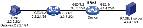
Procedure
1. Configure the RADIUS server: (This section uses the Linux Free RADIUS server as an example.)
# Add BRAS IP address 4.4.4.2 and secret radius to the clients.conf file.
client 4.4.4.2/32 {
ipaddr = 4.4.4.2
netmask=32
secret=radius
}
# Add the username and password to the users user information file. The username is the host IP address, and the password is radius.
2.2.2.2 Cleartext-Password :="radius"
2. Configure the BRAS:
a. Configure IP addresses for interfaces. (Details not shown.)
b. Configure a RADIUS scheme:
# Create a RADIUS scheme named rs1 and enter its view.
<Device> system-view
[Device] radius scheme rs1
# Configure primary servers and keys for authentication and accounting.
[Device-radius-rs1] primary authentication ipv6 4.4.4.1
[Device-radius-rs1] primary accounting ipv6 4.4.4.1
[Device-radius-rs1] key authentication simple radius
[Device-radius-rs1] key accounting simple radius
# Exclude the ISP name from the username sent to the RADIUS server.
[Device-radius-rs1] user-name-format without-domain
[Device-radius-rs1] quit
c. Configure the ISP domain:
# Create an ISP domain named dm1 and enter its view.
[Device] domain name dm1
# Configure dm1 to use RADIUS scheme rs1.
[Device-isp-dm1] authentication ipoe radius-scheme rs1
[Device-isp-dm1] authorization ipoe radius-scheme rs1
[Device-isp-dm1] accounting ipoe radius-scheme rs1
[Device-isp-dm1] quit
d. Configure IPoE:
# Enable IPoE and configure Layer 3 access mode on GigabitEthernet 3/1/2.
[Device] interface gigabitethernet 3/1/2
[Device–GigabitEthernet3/1/2] ip subscriber routed enable
# Enable unclassified-IP packet initiation on GigabitEthernet 3/1/2.
[Device–GigabitEthernet3/1/2] ip subscriber initiator unclassified-ip enable
# Specify dm1 as the ISP domain for unclassified-IP users.
[Device–GigabitEthernet3/1/2] ip subscriber unclassified-ip domain dm1
# Configure plaintext password radius for authentication.
[Device–GigabitEthernet3/1/2] ip subscriber password plaintext radius
[Device–GigabitEthernet3/1/2] quit
Verifying the configuration
# Display IPoE session information to verify that the host has come online.
[Device] display ip subscriber session
Type: D-DHCP S-Static U-Unclassified-IP N-NDRS
Interface IP address MAC address Type State
IPv6 address SVLAN/CVLAN VXLAN
Username
GE3/1/2 2.2.2.2 000c-29a6-b656 U/- Online
- -/- -
2.2.2.2
Example: Configuring DHCPv4 packet initiation (assigning a DHCP relay address pool)
Network configuration
As shown in Figure 9, the host accesses the BRAS as a DHCP user. It obtains configuration information from the DHCP server. The BRAS performs AAA for the host through the RADIUS server. After the DHCP user is abnormally logged out, the user can come online again through IP packet initiation.
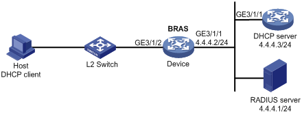
Procedure
1. Configure the RADIUS server: (This section uses the Linux Free RADIUS server as an example.)
# Add BRAS IP address 4.4.4.2 and secret radius to the clients.conf file.
client 4.4.4.2/32 {
ipaddr = 4.4.4.2
netmask=32
secret=radius
}
# Add the usernames and passwords of multiple users to the users user information file. For example, add a user whose username is the host MAC address 000c29a6b656 and password is radius.
000c29a6b656 Cleartext-Password :="radius"
000c29a6b657 Cleartext-Password :="radius"
……
2. Configure the DHCP server:
# Enable DHCP.
<DHCP-server> system-view
[DHCP-server] dhcp enable
# Create an IP address pool named pool1 and enter its view.
[DHCP-server] dhcp server ip-pool pool1
# Specify the subnet 3.3.3.0/24 for dynamic allocation in the pool.
[DHCP-server-dhcp-pool-pool1] network 3.3.3.0 24
# Specify gateway address 3.3.3.1 in the address pool.
[DHCP-server-dhcp-pool-pool1] gateway-list 3.3.3.1
# Exclude IP address 3.3.3.1 from dynamic allocation in the pool.
[DHCP-server-dhcp-pool-pool1] forbidden-ip 3.3.3.1
[DHCP-server-dhcp-pool-pool1] quit
# Configure a static route to specify the next hop of DHCP replies destined to network segment 3.3.3.0 as the IP address of the interface connected to the DHCP client, 4.4.4.2.
[DHCP-server] ip route-static 3.3.3.0 24 4.4.4.2
3. Configure the BRAS:
a. Configure IP addresses for interfaces. (Details not shown.)
b. Configure the DHCP relay agent:
# Enable DHCP.
<Device> system-view
[Device] dhcp enable
# Enable the DHCP relay agent to record client information in relay entries.
[Device] dhcp relay client-information record
# Disable the DHCP relay agent from periodically refreshing dynamic relay entries.
[Device] undo dhcp relay client-information refresh enable
# Enable DHCP server proxy on the relay agent on GigabitEthernet 3/1/2.
[Device] interface gigabitethernet 3/1/2
[Device–GigabitEthernet3/1/2] dhcp select relay proxy
[Device–GigabitEthernet3/1/2] quit
# Create a DHCP relay agent address pool pool1, specify a gateway address in the DHCP address pool, and specify a DHCP server for the address pool.
[Device] dhcp server ip-pool pool1
[Device-dhcp-pool-pool1] gateway-list 3.3.3.1 export-route
[Device-dhcp-pool-pool1] remote-server 4.4.4.3
[Device-dhcp-pool-pool1] quit
c. Configure a RADIUS scheme:
# Create a RADIUS scheme named rs1 and enter its view.
[Device] radius scheme rs1
# Configure primary servers and keys for authentication and accounting.
[Device-radius-rs1] primary authentication 4.4.4.1
[Device-radius-rs1] primary accounting 4.4.4.1
[Device-radius-rs1] key authentication simple radius
[Device-radius-rs1] key accounting simple radius
# Exclude the ISP name from the username sent to the RADIUS server.
[Device-radius-rs1] user-name-format without-domain
[Device-radius-rs1] quit
d. Configure the ISP domain:
# Create an ISP domain named dm1 and enter its view.
[Device] domain name dm1
# Configure ISP domain dm1 to use RADIUS scheme rs1 and assign a relay address pool.
[Device-isp-dm1] authentication ipoe radius-scheme rs1
[Device-isp-dm1] authorization ipoe radius-scheme rs1
[Device-isp-dm1] accounting ipoe radius-scheme rs1
[Device-isp-dm1] authorization-attribute ip-pool pool1
[Device-isp-dm1] quit
e. Configure IPoE:
# Enable IPoE and configure Layer 2 access mode on GigabitEthernet 3/1/2.
[Device–GigabitEthernet3/1/2] ip subscriber l2-connected enable
# Enable DHCP packet initiation on GigabitEthernet 3/1/2.
[Device–GigabitEthernet3/1/2] ip subscriber initiator dhcp enable
# Enable unclassified-IP packet initiation on GigabitEthernet 3/1/2.
[Device–GigabitEthernet3/1/2] ip subscriber initiator unclassified-ip enable
# Specify dm1 as the ISP domain for DHCP users.
[Device–GigabitEthernet3/1/2] ip subscriber dhcp domain dm1
# Configure plaintext password radius for authentication.
[Device–GigabitEthernet3/1/2] ip subscriber password plaintext radius
[Device–GigabitEthernet3/1/2] quit
Verifying the configuration
# Display IPoE session information to verify that the host has come online.
[Device] display ip subscriber session
Type: D-DHCP S-Static U-Unclassified-IP N-NDRS
Interface IP address MAC address Type State
IPv6 address SVLAN/CVLAN VXLAN
Username
GE3/1/2 3.3.3.2 000c-29a6-b656 D/- Online
- -/- -
000c29a6b656
# Delete the IPoE dynamic individual session to forcibly log out the user.
<Device> reset ip subscriber session
# Display information about the abnormally logged out DHCP user.
<Device> display ip subscriber abnormal-logout
Slot 3:
Interface IP address MAC address
GE3/1/2 3.3.3.2 000c-29a6-b656
# The abnormally logged out DHCP user comes online again through unclassified-IP packet initiation. After the user passes authentication, display IPoE individual session information. The output shows that the user obtains IP address 3.3.3.2 and is still a DHCP user.
<Device> display ip subscriber session
Type: D-DHCP S-Static U-Unclassified-IP N-NDRS
Interface IP address MAC address Type State
IPv6 address SVLAN/CVLAN VXLAN
Username
GE3/1/2 3.3.3.2 000c-29a6-b656 D/- Online
- -/- -
3.3.3.2
Example: Configuring DHCPv4 packet initiation (assigning a DHCP address pool group)
Network configuration
As shown in Figure 10, the host accesses the BRAS as a DHCP user. Users obtain IPv4 addresses from an address pool in the DHCP address pool group. The BRAS performs AAA for the host through the RADIUS server.
Procedure
1. Configure the RADIUS server: (This section uses the Linux Free RADIUS server as an example.)
# Add BRAS IP address 4.4.4.2 and secret radius to the clients.conf file.
client 4.4.4.2/32 {
ipaddr = 4.4.4.2
netmask=32
secret=radius
}
# Add the username and password to the users user information file. The username is the host MAC address and the password is radius.
000c29a6b656 Cleartext-Password :="radius"
2. Configure the DHCP server:
# Enable DHCP.
<DHCP-server> system-view
[DHCP-server] dhcp enable
# Create an IP address pool named pool2 and enter its view.
[DHCP-server] dhcp server ip-pool pool2
# Specify the subnet 2.2.2.0/24 for dynamic allocation in the address pool.
[DHCP-server-dhcp-pool-pool2] network 2.2.2.0 24
# Specify gateway address 2.2.2.1 in the address pool.
[DHCP-server-dhcp-pool-pool2] gateway-list 2.2.2.1
# Exclude IP address 2.2.2.1 from dynamic allocation in the address pool.
[DHCP-server-dhcp-pool-pool2] forbidden-ip 2.2.2.1
[DHCP-server-dhcp-pool-pool2] quit
# Configure a static route to specify the next hop of DHCP replies destined to network segment 2.2.2.0 as the IP address of the interface connected to the DHCP client, 4.4.4.2.
[DHCP-server] ip route-static 2.2.2.0 24 4.4.4.2
# Create an IP address pool named pool3 and enter its view.
[DHCP-server] dhcp server ip-pool pool3
# Specify the subnet 3.3.3.0/24 for dynamic allocation in the pool.
[DHCP-server-dhcp-pool-pool3] network 3.3.3.0 24
# Specify gateway address 3.3.3.1 in the address pool.
[DHCP-server-dhcp-pool-pool3] gateway-list 3.3.3.1
# Exclude IP address 3.3.3.1 from dynamic allocation in the pool.
[DHCP-server-dhcp-pool-pool3] forbidden-ip 3.3.3.1
[DHCP-server-dhcp-pool-pool3] quit
# Configure a static route to specify the next hop of DHCP replies destined to network segment 3.3.3.0 as the IP address of the interface connected to the DHCP client, 4.4.4.2.
[DHCP-server] ip route-static 3.3.3.0 24 4.4.4.2
3. Configure the BRAS:
a. Configure IP addresses for interfaces. (Details not shown.)
b. Configure the DHCP relay agent:
# Enable DHCP.
<Device> system-view
[Device] dhcp enable
# Enable the DHCP relay agent to record client information in relay entries.
[Device] dhcp relay client-information record
# Disable the DHCP relay agent from periodically refreshing dynamic relay entries.
[Device] undo dhcp relay client-information refresh enable
# Enable DHCP server proxy on the relay agent on GigabitEthernet 3/1/2.
[Device] interface gigabitethernet 3/1/2
[Device–GigabitEthernet3/1/2] dhcp select relay proxy
[Device–GigabitEthernet3/1/2] quit
# Create a local address pool pool1 and specify the subnet for dynamic allocation in the address pool.
[Device] dhcp server ip-pool pool1
[Device-dhcp-pool-pool1] network 1.1.1.0 24 export-route
# Specify gateway address 1.1.1.1 in the address pool.
[Device-dhcp-pool-pool1] gateway-list 1.1.1.1 export-route
# Exclude IP address 1.1.1.1 from dynamic allocation in the address pool.
[Device-dhcp-pool-pool1] forbidden-ip 1.1.1.1
[Device-dhcp-pool-pool1] quit
# Create a DHCP relay agent address pool pool2, specify a gateway address in the DHCP address pool, and specify a DHCP server for the address pool.
[Device] dhcp server ip-pool pool2
[Device-dhcp-pool-pool2] gateway-list 2.2.2.1 export-route
[Device-dhcp-pool-pool2] remote-server 4.4.4.3
# In the DHCP relay address pool, configure the same subnet and excluded IP address for dynamic allocation as the DHCP server associated with the DHCP relay address pool. Then, the DHCP address group can determine whether the DHCP server associated with the DHCP relay address pool has allocable addresses.
[Device-dhcp-pool-pool2] network 2.2.2.0 24
[Device-dhcp-pool-pool2] forbidden-ip 2.2.2.1
[Device-dhcp-pool-pool2] quit
# Create a DHCP relay agent address pool pool3, specify a gateway address in the DHCP address pool, and specify a DHCP server for the address pool.
[Device] dhcp server ip-pool pool3
[Device-dhcp-pool-pool3] gateway-list 3.3.3.1 export-route
[Device-dhcp-pool-pool3] remote-server 4.4.4.3
# In the DHCP relay address pool, configure the same subnet and excluded IP address for dynamic allocation as the DHCP server associated with the DHCP relay address pool. Then, the DHCP address group can determine whether the DHCP server associated with the DHCP relay address pool has allocable addresses.
[Device-dhcp-pool-pool3] network 3.3.3.0 24
[Device-dhcp-pool-pool3] forbidden-ip 3.3.3.1
[Device-dhcp-pool-pool3] quit
# Create DHCP address pool group poolgroup1, and assign DHCP address pool pool1 and DHCP relay address pools pool2 and pool3 to the DHCP address pool group.
[Device] dhcp pool-group poolgroup1
[Device -dhcp-pool-group-poolgroup1] pool pool1
[Device -dhcp-pool-group-poolgroup1] pool pool2
[Device -dhcp-pool-group-poolgroup1] pool pool3
[Device -dhcp-pool-group-poolgroup1] quit
c. Configure a RADIUS scheme:
# Create a RADIUS scheme named rs1 and enter its view.
[Device] radius scheme rs1
# Configure primary servers and keys for authentication and accounting.
[Device-radius-rs1] primary authentication 4.4.4.1
[Device-radius-rs1] primary accounting 4.4.4.1
[Device-radius-rs1] key authentication simple radius
[Device-radius-rs1] key accounting simple radius
# Exclude the ISP name from the username sent to the RADIUS server.
[Device-radius-rs1] user-name-format without-domain
[Device-radius-rs1] quit
d. Configure the ISP domain:
# Create an ISP domain named dm1 and enter its view.
[Device] domain name dm1
# Configure ISP domain dm1 to use RADIUS scheme rs1 and assign a DHCP address pool group.
[Device-isp-dm1] authentication ipoe radius-scheme rs1
[Device-isp-dm1] authorization ipoe radius-scheme rs1
[Device-isp-dm1] accounting ipoe radius-scheme rs1
[Device-isp-dm1] authorization-attribute ip-pool-group poolgroup1
[Device-isp-dm1] quit
e. Configure IPoE:
# Enable IPoE and configure Layer 2 access mode on GigabitEthernet 3/1/2.
[Device–GigabitEthernet3/1/2] ip subscriber l2-connected enable
# Enable DHCP packet initiation on GigabitEthernet 3/1/2.
[Device–GigabitEthernet3/1/2] ip subscriber initiator dhcp enable
# Specify ISP domain dm1 as the ISP domain for DHCP users.
[Device–GigabitEthernet3/1/2] ip subscriber dhcp domain dm1
# Configure plaintext password radius for authentication.
[Device–GigabitEthernet3/1/2] ip subscriber password plaintext radius
[Device–GigabitEthernet3/1/2] quit
Verifying the configuration
# After 253 users come online, display the statistics of the local DHCP address group pool1.
[Device] display dhcp server statistics pool pool1
Total IP addresses: 254
Free IP addresses: 0
Used: 253
Pool utilization: 100.00%
Bindings:
Automatic: 253
Manual: 0
Expired: 0
Conflicts: 0
The output shows that the usage of local DHCP address group pool1 is 100% and does not have allocable IP addresses.
# After more new users come online, display relay entries on the relay agent.
[Device] display dhcp relay client-information
Total number of client-information items: 1
Total number of dynamic items: 1
Total number of temporary items: 0
IP address MAC address Type Interface VPN name
2.1.1.2 000c-29a6-b656 Dynamic GE3/1/2 N/A
The output shows that: When the resources in local DHCP address group pool1 are exhausted, the address resources on the DHCP server associated with DHCP relay address pool pool2 are used to allocate IP addresses to new users.
Example: Configuring DHCPv6 packet initiation
Network configuration
As shown in Figure 11, the host accesses the BRAS as a DHCP user. It obtains configuration information from the DHCP server. The BRAS performs AAA for the host through the RADIUS server. After the DHCP user is abnormally logged out, the user can come online again through IP packet initiation.
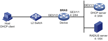
Procedure
1. Configure the RADIUS server: (This section uses the Linux Free RADIUS server as an example.)
# Add BRAS IP address 4::2 and secret radius to the clients.conf file.
client 4::2/64 {
ipaddr6 = 4::2
netmask=64
secret=radius
}
# Add the username and password to the users user information file. The username is the host MAC address and the password is radius.
000c29a6b656 Cleartext-Password :="radius"
2. Configure the DHCP server:
# Create an IP address pool named pool1 and enter its view.
<DHCP-server> system-view
[DHCP-server] ipv6 dhcp pool pool1
# Specify the subnet 3::0/64 and DNS server address 8::8 in the pool.
[DHCP-server-dhcp6-pool-pool1] network 3::0/64
[DHCP-server-dhcp6-pool-pool1] dns-server 8::8
# Enable the DHCPv6 server on GigabitEthernet 3/1/1.
[DHCP-server] interface gigabitethernet 3/1/1
[DHCP-server-GigabitEthernet3/1/1] ipv6 dhcp select server
[DHCP-server-GigabitEthernet3/1/1] quit
# Configure a static route to specify the next hop of DHCPv6 replies destined to network segment 3::0 as the IP address of the interface connected to the DHCPv6 client, 4::2.
[DHCP-server] ipv6 route-static 3::0 64 4::2
3. Configure the BRAS:
a. Configure IP addresses for interfaces. (Details not shown.)
b. Configure the DHCP relay agent:
# Create a DHCP relay agent address pool pool1, specify a gateway address in the DHCP address pool, and specify a DHCP server for the address pool.
<Device> system-view
[Device] ipv6 dhcp pool pool1
[Device-dhcp6-pool-pool1] gateway-list 3::1
[Device-dhcp6-pool-pool1] remote-server 4::3
[Device-dhcp6-pool-pool1] quit
# Enable the DHCPv6 relay agent on GigabitEthernet 3/1/2.
[Device] interface gigabitethernet 3/1/2
[Device–GigabitEthernet3/1/2] ipv6 dhcp select relay
# Automatically generate a link-local address for GigabitEthernet 3/1/2.
[Device–GigabitEthernet3/1/2] ipv6 address auto link-local
# Enable recording client information in DHCPv6 relay entries.
[Device–GigabitEthernet3/1/2] ipv6 dhcp relay client-information record
# Disable RA message suppression on GigabitEthernet 3/1/2.
[Device–GigabitEthernet3/1/2] undo ipv6 nd ra halt
# Set the managed address configuration flag (M) to 1 in RA advertisements to be sent. Then, the host uses a DHCPv6 server to obtain IPv6 addresses.
[Device–GigabitEthernet3/1/2] ipv6 nd autoconfig managed-address-flag
# Set the other stateful configuration flag (O) to 1 in RA advertisements to be sent. Then, the host uses a DHCPv6 server to obtain configuration information other than IPv6 addresses.
[Device–GigabitEthernet3/1/2] ipv6 nd autoconfig other-flag
[Device–GigabitEthernet3/1/2] quit
c. Configure a RADIUS scheme:
# Create a RADIUS scheme named rs1 and enter its view.
[Device] radius scheme rs1
# Configure primary servers and keys for authentication and accounting.
[Device-radius-rs1] primary authentication 4::1
[Device-radius-rs1] primary accounting 4::1
[Device-radius-rs1] key authentication simple radius
[Device-radius-rs1] key accounting simple radius
# Exclude the ISP name from the username sent to the RADIUS server.
[Device-radius-rs1] user-name-format without-domain
[Device-radius-rs1] quit
d. Configure the ISP domain:
# Create an ISP domain named dm1 and enter its view.
[Device] domain name dm1
# Configure ISP domain dm1 to use RADIUS scheme rs1 and assign a relay address pool.
[Device-isp-dm1] authentication ipoe radius-scheme rs1
[Device-isp-dm1] authorization ipoe radius-scheme rs1
[Device-isp-dm1] accounting ipoe radius-scheme rs1
[Device-isp-dm1] authorization-attribute ipv6-pool pool1
[Device-isp-dm1] quit
e. Configure IPoE:
# Enable IPoE and configure Layer 2 access mode on GigabitEthernet 3/1/2.
[Device] interface gigabitethernet 3/1/2
[Device–GigabitEthernet3/1/2] ip subscriber l2-connected enable
# Enable DHCPv6 packet initiation on GigabitEthernet 3/1/2.
[Device–GigabitEthernet3/1/2] ip subscriber initiator dhcpv6 enable
# Specify dm1 as the ISP domain for DHCP users.
[Device–GigabitEthernet3/1/2] ip subscriber dhcp domain dm1
# Configure plaintext password radius for authentication.
[Device–GigabitEthernet3/1/2] ip subscriber password plaintext radius
[Device–GigabitEthernet3/1/2] quit
Verifying the configuration
# Display IPoE session information to verify that the host has come online.
[Device] display ip subscriber session
Type: D-DHCP S-Static U-Unclassified-IP N-NDRS
Interface IP address MAC address Type State
IPv6 address SVLAN/CVLAN VXLAN
Username
GE3/1/2 - 000c-29a6-b656 -/D Online
3::2 -/- -
000c29a6b656
Example: Configuring a dual-stack user
Network configuration
As shown in Figure 12, the host accesses the BRAS as a dual-stack user. The host obtains IPv4 and IPv6 addresses from the DHCP server. The BRAS performs AAA for the host through the RADIUS server.
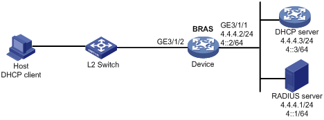
Procedure
1. Configure the RADIUS server: (This section uses the Linux Free RADIUS server as an example.)
# Add BRAS IP address 4.4.4.2 and secret radius to the clients.conf file.
client 4.4.4.2/32 {
ipaddr = 4.4.4.2
netmask=32
secret=radius
}
# Add the username and password to the users user information file. The username is the host MAC address and the password is radius.
000c29a6b656 Cleartext-Password :="radius"
2. Configure the DHCP server:
a. Configure the DHCPv4 address pool:
# Enable DHCP.
<DHCP-server> system-view
[DHCP-server] dhcp enable
# Create a DHCPv4 address pool named pool1 and enter its view.
[DHCP-server] dhcp server ip-pool pool1
# Specify the subnet 3.3.3.0/24 for dynamic allocation in the pool.
[DHCP-server-dhcp-pool-pool1] network 3.3.3.0 24
# Specify gateway address 3.3.3.1 in the address pool.
[DHCP-server-dhcp-pool-pool1] gateway-list 3.3.3.1
# Exclude IP address 3.3.3.1 from dynamic allocation in the pool.
[DHCP-server-dhcp-pool-pool1] forbidden-ip 3.3.3.1
[DHCP-server-dhcp-pool-pool1] quit
# Configure a static route to specify the next hop of DHCPv4 replies destined to network segment 3.3.3.0 as the IP address of the interface connected to the DHCPv4 client, 4.4.4.2.
[DHCP-server] ip route-static 3.3.3.0 24 4.4.4.2
b. Configure the DHCPv6 address pool:
# Create a DHCPv6 address pool named pool2 and enter its view.
[DHCP-server] ipv6 dhcp pool pool2
# Specify the subnet 3::0/64 for dynamic allocation in the pool.
[DHCP-server-dhcp6-pool-pool2] network 3::0/64
[DHCP-server-dhcp6-pool-pool2] quit
# Configure IP address 3::1 as unavailable.
[DHCP-server] ipv6 dhcp server forbidden-address 3::1
# Enable the DHCPv6 server on GigabitEthernet 1/0/1.
[DHCP-server] interface gigabitethernet 1/0/1
[DHCP-server-GigabitEthernet1/0/1] ipv6 dhcp select server
[DHCP-server-GigabitEthernet1/0/1] quit
# Configure a static route to specify the next hop of DHCPv6 replies destined to network segment 3::0 as the IP address of the interface connected to the DHCPv6 client, 4::2.
[DHCP-server] ipv6 route-static 3::0 64 4::2
3. Configure the BRAS:
a. Configure IP addresses for interfaces. (Details not shown.)
b. Configure the DHCP relay agent:
# Enable DHCP.
<Device> system-view
[Device] dhcp enable
# Enable the DHCP relay agent to record client information in relay entries.
[Device] dhcp relay client-information record
# Disable the DHCP relay agent from periodically refreshing dynamic relay entries.
[Device] undo dhcp relay client-information refresh enable
# Create a DHCP relay agent address pool pool1, specify a gateway address in the DHCP address pool, and specify a DHCP server for the address pool.
[Device] dhcp server ip-pool pool1
[Device-dhcp-pool-pool1] gateway-list 3.3.3.1 export-route
[Device-dhcp-pool-pool1] remote-server 4.4.4.3
[Device-dhcp-pool-pool1] quit
# Create a DHCP relay agent address pool pool2, specify a gateway address in the DHCPv6 address pool, and specify a DHCPv6 server for the address pool.
[Device] ipv6 dhcp pool pool2
[Device-dhcp6-pool-pool2] gateway-list 3::1
[Device-dhcp6-pool-pool2] remote-server 4::3
[Device-dhcp6-pool-pool2] quit
# Enable DHCP server proxy on the DHCPv4 relay agent and enable the DHCPv6 relay agent on GigabitEthernet 1/0/2.
[Device] interface gigabitethernet 1/0/2
[Device–GigabitEthernet1/0/2] dhcp select relay proxy
[Device–GigabitEthernet1/0/2] ipv6 dhcp select relay
# Automatically generate a link-local address for GigabitEthernet 1/0/2.
[Device–GigabitEthernet1/0/2] ipv6 address auto link-local
# Enable recording client information in DHCPv6 relay entries.
[Device–GigabitEthernet1/0/2] ipv6 dhcp relay client-information record
# Disable RA message suppression on GigabitEthernet 1/0/2.
[Device–GigabitEthernet1/0/2] undo ipv6 nd ra halt
# Set the managed address configuration flag (M) to 1 in RA advertisements to be sent. Then, the host uses a DHCPv6 server to obtain IPv6 addresses.
[Device–GigabitEthernet1/0/2] ipv6 nd autoconfig managed-address-flag
# Set the other stateful configuration flag (O) to 1 in RA advertisements to be sent. Then, the host uses a DHCPv6 server to obtain configuration information other than IPv6 addresses.
[Device–GigabitEthernet1/0/2] ipv6 nd autoconfig other-flag
[Device–GigabitEthernet1/0/2] quit
c. Configure a RADIUS scheme:
# Create a RADIUS scheme named rs1 and enter its view.
[Device] radius scheme rs1
# Configure primary servers and keys for authentication and accounting.
[Device-radius-rs1] primary authentication 4.4.4.1
[Device-radius-rs1] primary accounting 4.4.4.1
[Device-radius-rs1] key authentication simple radius
[Device-radius-rs1] key accounting simple radius
# Exclude the ISP name from the username sent to the RADIUS server.
[Device-radius-rs1] user-name-format without-domain
[Device-radius-rs1] quit
d. Configure the ISP domain:
# Create an ISP domain named dm1 and enter its view.
[Device] domain name dm1
# Configure ISP domain dm1 to use RADIUS scheme rs1 and assign relay address pools.
[Device-isp-dm1] authentication ipoe radius-scheme rs1
[Device-isp-dm1] authorization ipoe radius-scheme rs1
[Device-isp-dm1] accounting ipoe radius-scheme rs1
[Device-isp-dm1] authorization-attribute ip-pool pool1
[Device-isp-dm1] authorization-attribute ipv6-pool pool2
[Device-isp-dm1] quit
e. Configure IPoE:
# Enable IPoE and configure Layer 2 access mode on GigabitEthernet 1/0/2.
[Device] interface gigabitethernet 1/0/2
[Device–GigabitEthernet1/0/2] ip subscriber l2-connected enable
# Enable DHCPv4 packet initiation on GigabitEthernet 1/0/2.
[Device–GigabitEthernet1/0/2] ip subscriber initiator dhcp enable
# Enable DHCPv6 packet initiation on GigabitEthernet 1/0/2.
[Device–GigabitEthernet1/0/2] ip subscriber initiator dhcp enable
# Specify dm1 as the ISP domain for DHCP users.
[Device–GigabitEthernet1/0/2] ip subscriber dhcp domain dm1
# Configure plaintext password radius for authentication.
[Device–GigabitEthernet1/0/2] ip subscriber password plaintext radius
[Device–GigabitEthernet1/0/2] quit
Verifying the configuration
# Display IPoE session information to verify that the host has come online.
[Device] display ip subscriber session
Type: D-DHCP S-Static U-Unclassified-IP N-NDRS
Interface IP address MAC address Type State
IPv6 address SVLAN/CVLAN VXLAN
Username
GE1/0/2 3.3.3.2 000c-29a6-b656 D/D Online
3::2 -/- -
000c29a6b656
Example: Configuring IPv6 ND RS packet initiation (AAA-authorized prefix)
Network configuration
As shown in Figure 13, the host accesses the BRAS as an IPv6 ND RS user. The BRAS performs AAA for the host through the RADIUS server.
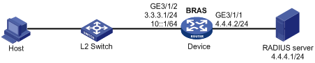
Procedure
1. Configure the RADIUS server: (This section uses the Linux Free RADIUS server as an example.)
# Add BRAS IP address 4.4.4.2 and secret radius to the clients.conf file.
client 4.4.4.2/32 {
ipaddr = 4.4.4.2
netmask=32
secret=radius
}
# Add the username, password, and authorized IPv6 prefix to the users user information file. The username is the host MAC address, the password is radius, and the IPv6 prefix is 10::10/64.
000c29a6b656 Cleartext-Password :="radius"
Framed-IPv6-Prefix =10::10/64
2. Configure the BRAS:
a. Configure IP addresses for interfaces. (Details not shown.)
b. Disable RA message suppression on GigabitEthernet 3/1/2.
<Device> system-view
[Device] interface gigabitethernet 3/1/2
[Device–GigabitEthernet3/1/2] undo ipv6 nd ra halt
[Device–GigabitEthernet3/1/2] quit
c. Configure a RADIUS scheme:
# Create a RADIUS scheme named rs1 and enter its view.
[Device] radius scheme rs1
# Configure primary servers and keys for authentication and accounting.
[Device-radius-rs1] primary authentication 4.4.4.1
[Device-radius-rs1] primary accounting 4.4.4.1
[Device-radius-rs1] key authentication simple radius
[Device-radius-rs1] key accounting simple radius
# Exclude the ISP name from the username sent to the RADIUS server.
[Device-radius-rs1] user-name-format without-domain
[Device-radius-rs1] quit
d. Configure the ISP domain:
# Create an ISP domain named dm1 and enter its view.
[Device] domain name dm1
# Configure dm1 to use RADIUS scheme rs1.
[Device-isp-dm1] authentication ipoe radius-scheme rs1
[Device-isp-dm1] authorization ipoe radius-scheme rs1
[Device-isp-dm1] accounting ipoe radius-scheme rs1
[Device-isp-dm1] quit
e. Configure IPoE:
# Enable IPoE and configure Layer 2 access mode on GigabitEthernet 3/1/2.
[Device] interface gigabitethernet 3/1/2
[Device–GigabitEthernet3/1/2] ip subscriber l2-connected enable
# Enable IPv6 ND RS packet initiation on GigabitEthernet 3/1/2.
[Device–GigabitEthernet3/1/2] ip subscriber initiator ndrs enable
# Specify dm1 as the ISP domain for IPv6 ND RS users.
[Device–GigabitEthernet3/1/2] ip subscriber ndrs domain dm1
# Configure plaintext password radius for authentication.
[Device–GigabitEthernet3/1/2] ip subscriber password plaintext radius
[Device–GigabitEthernet3/1/2] quit
Verifying the configuration
# Display IPoE session information to verify that the host has come online.
[Device] display ip subscriber session
Type: D-DHCP S-Static U-Unclassified-IP N-NDRS
Interface IP address MAC address Type State
IPv6 address SVLAN/CVLAN VXLAN
Username
GE3/1/2 - 000c-29a6-b656 -/N Online
10::20C:29FF:FEA6:B6 -/- -
56
000c29a6b656
Example: Configuring IPv6 ND RS packet initiation (ND prefix pool-authorized prefix)
Network configuration
As shown in Figure 14, the host accesses the BRAS as an IPv6 ND RS user. The BRAS performs AAA for the host through the RADIUS server.
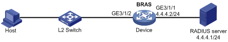
Procedure
1. Configure the RADIUS server: (This section uses the Linux Free RADIUS server as an example.)
# Add BRAS IP address 4.4.4.2 and secret radius to the clients.conf file.
client 4.4.4.2/32 {
ipaddr = 4.4.4.2
netmask=32
secret=radius
}
# Add the username and password to the users user information file. The username is the host MAC address, and the password is radius.
000c29a6b656 Cleartext-Password :="radius"
2. Configure the BRAS:
a. Configure IP addresses for interfaces. (Details not shown.)
b. Disable RA message suppression on GigabitEthernet 3/1/2.
<Device> system-view
[Device] interface gigabitethernet 3/1/2
[Device–GigabitEthernet3/1/2] undo ipv6 nd ra halt
c. Automatically generate a link-local address for GigabitEthernet 3/1/2.
[Device–GigabitEthernet3/1/2] ipv6 address auto link-local
[Device–GigabitEthernet3/1/2] quit
d. Configure the DHCP server:
# Create prefix pool 1 that contains the prefix 10::/32 and specify the length of prefixes to be assigned as 64. Prefix pool 1 can assign 4294967296 prefixes in the range of 10::/64 to 10:0:FFFF:FFFF::/64.
[Device] ipv6 dhcp prefix-pool 1 prefix 10::/32 assign-len 64
# Create an IPv6 address pool named pool1, and reference prefix pool 1.
[Device] ipv6 pool pool1
[Device-ipv6-pool-pool1] prefix-pool 1
[Device-ipv6-pool-pool1] quit
# Enable the DHCPv6 server on GigabitEthernet 3/1/2.
[Device] interface gigabitethernet 3/1/2
[Device-GigabitEthernet3/1/2] ipv6 dhcp select server
[Device–GigabitEthernet3/1/2] quit
e. Configure a RADIUS scheme:
# Create a RADIUS scheme named rs1 and enter its view.
[Device] radius scheme rs1
# Configure primary servers and keys for authentication and accounting.
[Device-radius-rs1] primary authentication 4.4.4.1
[Device-radius-rs1] primary accounting 4.4.4.1
[Device-radius-rs1] key authentication simple radius
[Device-radius-rs1] key accounting simple radius
# Exclude the ISP name from the username sent to the RADIUS server.
[Device-radius-rs1] user-name-format without-domain
[Device-radius-rs1] quit
f. Configure the ISP domain:
# Create an ISP domain named dm1 and enter its view.
[Device] domain name dm1
# Configure dm1 to use RADIUS scheme rs1, and authorize an ND prefix pool and IPv6 DNS address pool to users.
[Device-isp-dm1] authentication ipoe radius-scheme rs1
[Device-isp-dm1] authorization ipoe radius-scheme rs1
[Device-isp-dm1] accounting ipoe radius-scheme rs1
[Device-isp-dm1] authorization-attribute ipv6-nd-prefix-pool pool1
[Device-isp-dm1] authorization-attribute primary-dns ipv6 2:2::3
[Device-isp-dm1] quit
g. Configure IPoE:
# Enable IPoE and configure Layer 2 access mode on GigabitEthernet 3/1/2.
[Device] interface gigabitethernet 3/1/2
[Device–GigabitEthernet3/1/2] ip subscriber l2-connected enable
# Enable IPv6 ND RS packet initiation on GigabitEthernet 3/1/2.
[Device–GigabitEthernet3/1/2] ip subscriber initiator ndrs enable
# Specify dm1 as the ISP domain for IPv6 ND RS users.
[Device–GigabitEthernet3/1/2] ip subscriber ndrs domain dm1
# Configure plaintext password radius for authentication.
[Device–GigabitEthernet3/1/2] ip subscriber password plaintext radius
[Device–GigabitEthernet3/1/2] quit
Verifying the configuration
# Display IPoE session information to verify that the host has come online.
[Device] display ip subscriber session
Type: D-DHCP S-Static U-Unclassified-IP N-NDRS
Interface IP address MAC address Type State
IPv6 address SVLAN/CVLAN VXLAN
Username
GE3/1/2 - 000c-29a6-b656 -/N Online
10:: -/- -
000c29a6b656
Example: Configuring ARP packet initiation
Network configuration
As shown in Figure 15, an ARP-initiated static user accesses the BRAS through a Layer 2 device and is assigned the gateway IP address 3.3.3.1. The BRAS performs AAA for the host through the RADIUS server.
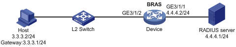
Procedure
1. Configure the RADIUS server: (This section uses the Linux Free RADIUS server as an example.)
# Add BRAS IP address 4.4.4.2 and secret radius to the clients.conf file.
client 4.4.4.2/32 {
ipaddr = 4.4.4.2
netmask=32
secret=radius
}
# Add the username and password to the users user information file. The username is the host IP address 3.3.3.2. The password is radius.
3.3.3.2 Cleartext-Password :="radius"
2. Configure the BRAS:
a. Configure IP addresses for interfaces. (Details not shown.)
b. Configure a RADIUS scheme:
# Create a RADIUS scheme named rs1 and enter its view.
<Device> system-view
[Device] radius scheme rs1
# Configure primary servers and keys for authentication and accounting.
[Device-radius-rs1] primary authentication 4.4.4.1
[Device-radius-rs1] primary accounting 4.4.4.1
[Device-radius-rs1] key authentication simple radius
[Device-radius-rs1] key accounting simple radius
# Exclude the ISP name from the username sent to the RADIUS server.
[Device-radius-rs1] user-name-format without-domain
[Device-radius-rs1] quit
c. Configure the ISP domain:
# Create an ISP domain named dm1 and enter its view.
[Device] domain name dm1
# Configure ISP domain dm1 to use RADIUS scheme rs1.
[Device-isp-dm1] authentication ipoe radius-scheme rs1
[Device-isp-dm1] authorization ipoe radius-scheme rs1
[Device-isp-dm1] accounting ipoe radius-scheme rs1
[Device-isp-dm1] quit
d. Configure the gateway for users.
# Enable DHCP globally.
[Device] dhcp enable
# Create address pool pool1, and specify the user gateway address as 3.3.3.1.
[Device] dhcp server ip-pool pool1
[Device-dhcp-pool-pool1] gateway-list 3.3.3.1 export-route
[Device-dhcp-pool-pool1] quit
e. Configure IPoE:
# Enable IPoE and configure Layer 2 access mode on GigabitEthernet 3/1/2.
[Device] interface gigabitethernet 3/1/2
[Device–GigabitEthernet3/1/2] ip subscriber l2-connected enable
# Enable ARP packet initiation on GigabitEthernet 3/1/2.
[Device–GigabitEthernet3/1/2] ip subscriber initiator arp enable
# Configure a static individual session with IP address 3.3.3.2 and ISP domain dm1 on GigabitEthernet 3/1/2.
[Device–GigabitEthernet3/1/2] ip subscriber session static ip 3.3.3.2 domain dm1
# Configure plaintext password radius for authentication.
[Device–GigabitEthernet3/1/2] ip subscriber password plaintext radius
[Device–GigabitEthernet3/1/2] quit
Verifying the configuration
# Display IPoE session information to verify that the host has come online.
[Device] display ip subscriber session
Type: D-DHCP S-Static U-Unclassified-IP N-NDRS
Interface IP address MAC address Type State
IPv6 address SVLAN/CVLAN VXLAN
Username
GE3/1/2 3.3.3.2 147b-1924-0206 S/- Online
- -/- -
3.3.3.2
Example: Configuring NS/NA packet initiation
Network configuration
As shown in Figure 16, the host accesses the BRAS as a static NS/NA user. The BRAS performs AAA for the host through the RADIUS server.
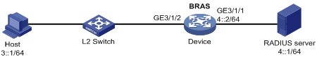
Procedure
1. Configure the RADIUS server: (This section uses the Linux Free RADIUS server as an example.)
# Add BRAS IP address 4::2 and secret radius to the clients.conf file.
client 4::2/64 {
ipaddr6 = 4::2
netmask=64
secret=radius
}
# Add the username and password to the users user information file. The username is the host MAC address and the password is radius.
0010-9400-0002 Cleartext-Password :="radius"
2. Configure the BRAS:
a. Configure IP addresses for interfaces. (Details not shown.)
b. Configure a RADIUS scheme:
# Create a RADIUS scheme named rs1 and enter its view.
<Device> system-view
[Device] radius scheme rs1
# Configure primary servers and keys for authentication and accounting.
[Device-radius-rs1] primary authentication ipv6 4::1
[Device-radius-rs1] primary accounting ipv6 4::1
[Device-radius-rs1] key authentication simple radius
[Device-radius-rs1] key accounting simple radius
# Exclude the ISP name from the username sent to the RADIUS server.
[Device-radius-rs1] user-name-format without-domain
[Device-radius-rs1] quit
c. Configure the ISP domain:
# Create an ISP domain named dm1 and enter its view.
[Device] domain name dm1
# Configure ISP domain dm1 to use RADIUS scheme rs1.
[Device-isp-dm1] authentication ipoe radius-scheme rs1
[Device-isp-dm1] authorization ipoe radius-scheme rs1
[Device-isp-dm1] accounting ipoe radius-scheme rs1
[Device-isp-dm1] quit
d. Configure IPoE:
# Automatically generate a link-local address for GigabitEthernet 3/1/2. The IPv6 address is to be used as the gateway of users.
[Device] interface gigabitethernet 3/1/2
[Device–GigabitEthernet3/1/2] ipv6 address auto link-local
# Enable IPoE and configure Layer 2 access mode on GigabitEthernet 3/1/2.
[Device–GigabitEthernet3/1/2] ip subscriber l2-connected enable
# Enable NS/NA packet initiation on GigabitEthernet 3/1/2.
[Device–GigabitEthernet3/1/2] ip subscriber initiator nsna enable
# Create a static session with the IPv6 address 3::1 and authentication domain dm1.
[Device–GigabitEthernet3/1/2] ip subscriber session static ipv6 3::1 domain dm1
# Configure plaintext password radius for authentication.
[Device–GigabitEthernet3/1/2] ip subscriber password plaintext radius
[Device–GigabitEthernet3/1/2] quit
Verifying the configuration
# Display IPoE session information to verify that the host has come online.
[Device] display ip subscriber session
Type: D-DHCP S-Static U-Unclassified-IP N-NDRS
Interface IP address MAC address Type State
IPv6 address SVLAN/CVLAN VXLAN
Username
GE1/0/2 - 0010-9400-0002 -/S Online
3::1 -/- -
3::1
Example: Configuring subnet-leased users
Network configuration
As shown in Figure 17, three hosts access the BRAS as subnet-leased users. The BRAS performs AAA for the hosts through the RADIUS server.
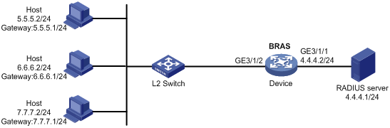
Procedure
1. Configure the RADIUS server: (This section uses the Linux Free RADIUS server as an example.)
# Add BRAS IP address 4.4.4.2 and secret radius to the clients.conf file.
client 4.4.4.2/32 {
ipaddr = 4.4.4.2
netmask=32
secret=radius
}
# Add usernames and passwords to the users user information file. Usernames for the three subnet user groups are us1, us2, and us3. Passwords for the three subnet user groups are pw1, pw2, and pw3.
us1 Cleartext-Password :="pw1"
us2 Cleartext-Password :="pw2"
us3 Cleartext-Password :="pw3"
2. Configure the BRAS:
a. Configure IP addresses for interfaces. (Details not shown.)
b. Configure a RADIUS scheme:
# Create a RADIUS scheme named rs1 and enter its view.
<Device> system-view
[Device] radius scheme rs1
# Configure primary servers and keys for authentication and accounting.
[Device-radius-rs1] primary authentication 4.4.4.1
[Device-radius-rs1] primary accounting 4.4.4.1
[Device-radius-rs1] key authentication simple radius
[Device-radius-rs1] key accounting simple radius
# Exclude the ISP name from the username sent to the RADIUS server.
[Device-radius-rs1] user-name-format without-domain
[Device-radius-rs1] quit
c. Configure the ISP domain:
# Create an ISP domain named dm1 and enter its view.
[Device] domain name dm1
# Configure dm1 to use RADIUS scheme rs1.
[Device-isp-dm1] authentication ipoe radius-scheme rs1
[Device-isp-dm1] authorization ipoe radius-scheme rs1
[Device-isp-dm1] accounting ipoe radius-scheme rs1
[Device-isp-dm1] quit
d. Configure IPoE:
# Enable IPoE and configure Layer 2 access mode on GigabitEthernet 3/1/2.
[Device] interface gigabitethernet 3/1/2
[Device–GigabitEthernet3/1/2] ip subscriber l2-connected enable
# Configure three subnet-leased users and specify their usernames, passwords, and ISP domains.
[Device–GigabitEthernet3/1/2] ip subscriber subnet-leased ip 5.5.5.0 24 username us1 password plaintext pw1 domain dm1
[Device–GigabitEthernet3/1/2] ip subscriber subnet-leased ip 6.6.6.0 24 username us2 password plaintext pw2 domain dm1
[Device–GigabitEthernet3/1/2] ip subscriber subnet-leased ip 7.7.7.0 24 username us3 password plaintext pw3 domain dm1
[Device–GigabitEthernet3/1/2] quit
Verifying the configuration
# Display IPoE session information to verify that the host has come online.
[Device] display ip subscriber subnet-leased
Basic:
Access interface : GE3/1/2
VPN instance : N/A
Username : us1
Network : 5.5.5.0/24
User ID : 0x38060000
State : Online
Service node : Slot 3 CPU 0
Domain : dm1
Login time : May 14 20:08:35 2014
Online time (hh:mm:ss) : 00:16:37
IPv4 total users : 10
AAA:
ITA policy name : N/A
IP pool : N/A
Primary DNS server : N/A
Secondary DNS server : N/A
Session idle cut : N/A
Session duration : N/A, remaining: N/A
Traffic quota : N/A
Traffic remained : N/A
Acct start-fail action : Online
Acct update-fail action : Online
Acct quota-out action : Offline
Dual-stack accounting mode : N/A
Max IPv4 multicast addresses: 4
IPv4 multicast address list : N/A
QoS:
User profile : N/A
Session group profile : N/A
User group ACL : N/A
Inbound CAR : N/A
Outbound CAR : N/A
Inbound user priority : N/A
Outbound user priority : N/A
Flow statistic:
Uplink packets/bytes : 223423/28598144
Downlink packets/bytes : 5802626/742736000
Basic:
Access interface : GE3/1/2
VPN instance : N/A
Username : us2
Network : 6.6.6.0/24
User ID : 0x38060001
State : Online
Service node : Slot 3 CPU 0
Domain : dm1
Login time : May 14 20:08:35 2014
Online time (hh:mm:ss) : 00:10:37
IPv4 total users : 10
AAA:
ITA policy name : N/A
IP pool : N/A
Primary DNS server : N/A
Secondary DNS server : N/A
Session idle cut : N/A
Session duration : N/A, remaining: N/A
Traffic quota : N/A
Traffic remained : N/A
Acct start-fail action : Online
Acct update-fail action : Online
Acct quota-out action : Offline
Dual-stack accounting mode : N/A
Max IPv4 multicast addresses: 4
IPv4 multicast address list : N/A
QoS:
User profile : N/A
Session group profile : N/A
User group ACL : N/A
Inbound CAR : N/A
Outbound CAR : N/A
Inbound user priority : N/A
Outbound user priority : N/A
Flow statistic:
Uplink packets/bytes : 223423/28598144
Downlink packets/bytes : 5802626/742736000
Basic:
Access interface : GE3/1/2
VPN instance : N/A
Username : us3
Network : 7.7.7.0/24
User ID : 0x38060002
State : Online
Service node : Slot 3 CPU 0
Domain : dm1
Login time : May 14 20:08:35 2014
Online time (hh:mm:ss) : 00:16:03
IPv4 total users : 10
AAA:
ITA policy name : N/A
IP pool : N/A
Primary DNS server : N/A
Secondary DNS server : N/A
Session idle cut : N/A
Session duration : N/A, remaining: N/A
Traffic quota : N/A
Traffic remained : N/A
Acct start-fail action : Online
Acct update-fail action : Online
Acct quota-out action : Offline
Dual-stack accounting mode : N/A
Max IPv4 multicast addresses: 4
IPv4 multicast address list : N/A
QoS:
User profile : N/A
Session group profile : N/A
User group ACL : N/A
Inbound CAR : N/A
Outbound CAR : N/A
Inbound user priority : N/A
Outbound user priority : N/A
Flow statistic:
Uplink packets/bytes : 223423/28598144
Downlink packets/bytes : 5802626/742736000
Example: Configuring an interface-leased user
Network configuration
As shown in Figure 18, three hosts access the BRAS as one interface-leased user. The BRAS performs AAA for the hosts through the RADIUS server.
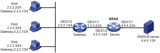
Procedure
1. Configure the RADIUS server: (This section uses the Linux Free RADIUS server as an example.)
# Add the BRAS IP address 4.4.4.2 and the secret radius to the clients.conf file.
client 4.4.4.2/32 {
ipaddr = 4.4.4.2
netmask=32
secret=radius
}
# Add host username and password to the users user information file. The username is us1 and the password is pw1.
us1 Cleartext-Password :="pw1"
2. Configure the BRAS:
a. Configure IP addresses for interfaces. (Details not shown.)
b. Configure a RADIUS scheme:
# Create a RADIUS scheme named rs1 and enter its view.
<Device> system-view
[Device] radius scheme rs1
# Configure primary servers and keys for authentication and accounting.
[Device-radius-rs1] primary authentication 4.4.4.1
[Device-radius-rs1] primary accounting 4.4.4.1
[Device-radius-rs1] key authentication simple radius
[Device-radius-rs1] key accounting simple radius
# Exclude the ISP name from the username sent to the RADIUS server.
[Device-radius-rs1] user-name-format without-domain
[Device-radius-rs1] quit
c. Configure the ISP domain:
# Create an ISP domain named dm1 and enter its view.
[Device] domain name dm1
# Configure dm1 to use RADIUS scheme rs1.
[Device-isp-dm1] authentication ipoe radius-scheme rs1
[Device-isp-dm1] authorization ipoe radius-scheme rs1
[Device-isp-dm1] accounting ipoe radius-scheme rs1
[Device-isp-dm1] quit
d. Configure IPoE:
# Enable IPoE and configure Layer 3 access mode on GigabitEthernet 3/1/2.
[Device] interface gigabitethernet 3/1/2
[Device–GigabitEthernet3/1/2] ip subscriber routed enable
# Configure the interface-leased user and specify its username, password, and ISP domain.
[Device–GigabitEthernet3/1/2] ip subscriber interface-leased username us1 password plaintext pw1 domain dm1
[Device–GigabitEthernet3/1/2] quit
Verifying the configuration
# Display IPoE session information to verify that the host has come online.
[Device] display ip subscriber interface-leased
Basic:
Access interface : GE3/1/2
VPN instance : N/A
Username : us1
User ID : 0x30000000
State : Online
Service node : Slot 3 CPU 0
Domain : dm1
Login time : May 14 20:04:42 2014
Online time (hh:mm:ss) : 00:16:37
IPv4 total users : 0
IPv6 total users : 0
AAA:
ITA policy name : N/A
IP pool : N/A
IPv6 pool : N/A
Primary DNS server : N/A
Secondary DNS server : N/A
Primary IPv6 DNS server : N/A
Secondary IPv6 DNS server : N/A
Session idle cut : N/A
Session duration : N/A, remaining: N/A
Traffic quota : N/A
Traffic remained : N/A
Acct start-fail action : Online
Acct update-fail action : Online
Acct quota-out action : Offline
Dual-stack accounting mode : Merge
Max IPv4 multicast addresses: 4
IPv4 multicast address list : N/A
Max IPv6 multicast addresses: 4
IPv6 multicast address list : N/A
QoS:
User profile : N/A
Session group profile : N/A
User group ACL : N/A
Inbound CAR : N/A
Outbound CAR : N/A
Inbound user priority : N/A
Outbound user priority : N/A
Flow statistic:
Uplink packets/bytes : 16734145/2141970560
Downlink packets/bytes : 22314327/2856233728
IPv6 uplink packets/bytes : 0/0
IPv6 downlink packets/bytes : 0/0
Example: Configuring an L2VPN-leased user
Network configuration
As shown in Figure 19, an L2VPN-leased host accesses the BRAS through a Layer 2 device. The BRAS performs AAA for the hosts through the RADIUS server. The username and password are us1 and pw1, respectively.
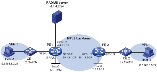
Procedure
1. Configure the RADIUS server: (This section uses the Linux Free RADIUS server as an example.)
# Add the BRAS IP address 4.4.4.2 and the secret radius to the clients.conf file.
client 4.4.4.2/32 {
ipaddr = 4.4.4.2
netmask=32
secret=radius
}
# Add host username and password to the users user information file. The username is us1 and the password is pw1.
us1 Cleartext-Password :="pw1"
2. Configure PE 2:
# Configure an LSR ID.
<PE2> system-view
[PE2] interface loopback 0
[PE2-LoopBack0] ip address 2.2.2.9 32
[PE2-LoopBack0] quit
[PE2] mpls lsr-id 2.2.2.9
# Enable L2VPN.
[PE2] l2vpn enable
# Enable LDP globally.
[PE2] mpls ldp
[PE2-ldp] quit
# Configure GigabitEthernet 3/1/2 (the interface connected to PE 1), and enable LDP on the interface.
[PE2] interface gigabitethernet 3/1/2
[PE2-GigabitEthernet3/1/2] ip address 20.1.1.2 24
[PE2-GigabitEthernet3/1/2] mpls enable
[PE2-GigabitEthernet3/1/2] mpls ldp enable
[PE2-GigabitEthernet3/1/2] quit
# Configure OSPF for LDP to create LSPs.
[PE2] ospf
[PE2-ospf-1] area 0
[PE2-ospf-1-area-0.0.0.0] network 20.1.1.0 0.0.0.255
[PE2-ospf-1-area-0.0.0.0] network 2.2.2.9 0.0.0.0
[PE2-ospf-1-area-0.0.0.0] quit
[PE2-ospf-1] quit
# Create a VSI and configure the peer PE.
[PE2] vsi vpn1
[PE2-vsi-vpn1] pwsignaling static
[PE2-vsi-vpn1-static] peer 1.1.1.9 pw-id 3 in-label 100 out-label 100
[PE2-vsi-vpn1-static-1.1.1.9-3] quit
[PE2-vsi-vpn1-static] quit
[PE2-vsi-vpn1] quit
# Bind GigabitEthernet 3/1/1 to the VSI. GigabitEthernet 3/1/1 does not require IP address configuration.
[PE2] interface gigabitethernet 3/1/1
[PE2-GigabitEthernet3/1/1] xconnect vsi vpn1
[PE2-GigabitEthernet3/1/1] quit
3. Configure PE1:
a. Configure VPLS:
# Configure an LSR ID.
<PE1> system-view
[PE1] interface loopback 0
[PE1-LoopBack0] ip address 1.1.1.9 32
[PE1-LoopBack0] quit
[PE1] mpls lsr-id 1.1.1.9
# Enable L2VPN.
[PE1] l2vpn enable
# Enable LDP globally.
[PE1] mpls ldp
[PE1-ldp] quit
# Configure GigabitEthernet 3/1/2 (the interface connected to PE 2), and enable LDP on the interface.
[PE1] interface gigabitethernet 3/1/2
[PE1-GigabitEthernet3/1/2] ip address 20.1.1.1 24
[PE1-GigabitEthernet3/1/2] mpls enable
[PE1-GigabitEthernet3/1/2] mpls ldp enable
[PE1-GigabitEthernet3/1/2] quit
# Configure OSPF for LDP to create LSPs.
[PE1] ospf
[PE1-ospf-1] area 0
[PE1-ospf-1-area-0.0.0.0] network 20.1.1.0 0.0.0.255
[PE1-ospf-1-area-0.0.0.0] network 1.1.1.9 0.0.0.0
[PE1-ospf-1-area-0.0.0.0] quit
[PE1-ospf-1] quit
# Create a VSI and configure the peer PE.
[PE1] vsi vpn1
[PE1-vsi-vpn1] pwsignaling static
[PE1-vsi-vpn1-static] peer 2.2.2.9 pw-id 3 in-label 100 out-label 100
[PE1-vsi-vpn1-static-2.2.2.9-3] quit
[PE1-vsi-vpn1-static] quit
[PE1-vsi-vpn1] quit
# Bind GigabitEthernet 3/1/1 to the VSI. GigabitEthernet 3/1/1 does not require IP address configuration.
[PE1] interface gigabitethernet 3/1/1
[PE1-GigabitEthernet3/1/1] xconnect vsi vpn1
[PE1-GigabitEthernet3/1/1] quit
b. Configure a RADIUS scheme:
# Create a RADIUS scheme named rs1 and enter its view.
<PE1> system-view
[PE1] radius scheme rs1
# Configure primary servers and keys for authentication and accounting.
[PE1-radius-rs1] primary authentication 4.4.4.1
[PE1-radius-rs1] primary accounting 4.4.4.1
[PE1-radius-rs1] key authentication simple radius
[PE1-radius-rs1] key accounting simple radius
# Exclude the ISP name from the username sent to the RADIUS server.
[PE1-radius-rs1] user-name-format without-domain
[PE1-radius-rs1] quit
c. Configure the ISP domain:
# Create an ISP domain named dm1 and enter its view.
[PE1] domain name dm1
# Configure ISP domain dm1 to use RADIUS scheme rs1.
[PE1-isp-dm1] authentication ipoe radius-scheme rs1
[PE1-isp-dm1] authorization ipoe radius-scheme rs1
[PE1-isp-dm1] accounting ipoe radius-scheme rs1
[PE1-isp-dm1] quit
d. Configure IPoE:
# Enable IPoE and configure Layer 2 access mode on GigabitEthernet 3/1/1.
[PE1] interface gigabitethernet 3/1/1
[PE1–GigabitEthernet3/1/1] ip subscriber l2-connected enable
# Configure the L2VPN-leased user and specify the username, password, and ISP domain for the user.
[PE1–GigabitEthernet3/1/1] ip subscriber l2vpn-leased username us1 password plaintext pw1 domain dm1
[PE1–GigabitEthernet3/1/1] quit
Verifying the configuration
# Display IPoE session information to verify that the host has come online.
[PE1] display ip subscriber l2vpn-leased
Basic:
Access interface : GE3/1/1
VPN instance : N/A
Username : us1
User ID : 0x30000000
State : Online
Service node : Slot 3 CPU 0
Domain : dm1
Login time : May 14 20:04:42 2014
Online time (hh:mm:ss) : 00:16:37
AAA:
ITA policy name : N/A
IP pool : N/A
IPv6 pool : N/A
Primary DNS server : N/A
Secondary DNS server : N/A
Primary IPv6 DNS server : N/A
Secondary IPv6 DNS server : N/A
Session idle cut : N/A
Session duration : N/A, remaining: N/A
Traffic quota : N/A
Traffic remained : N/A
Acct start-fail action : Online
Acct update-fail action : Online
Acct quota-out action : Offline
Dual-stack accounting mode : N/A
Max IPv4 multicast addresses: 0
IPv4 multicast address list : N/A
Max IPv6 multicast addresses: 0
IPv6 multicast address list : N/A
QoS:
User profile : N/A
Session group profile : N/A
User group ACL : N/A
Inbound CAR : N/A
Outbound CAR : N/A
Inbound user priority : N/A
Outbound user priority : N/A
Flow statistic:
Uplink packets/bytes : 16734145/2141970560
Downlink packets/bytes : 22314327/2856233728
IPv6 uplink packets/bytes : 0/0
IPv6 downlink packets/bytes : 0/0
Example: Configuring a VPN DHCP user
Network configuration
As shown in Figure 20, the host in a VPN accesses the BRAS as a DHCP user. The BRAS performs AAA for the host through the RADIUS server.
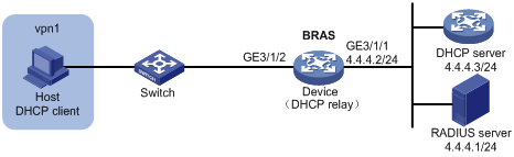
Procedure
1. Configure the RADIUS server: (This section uses the Linux Free RADIUS server as an example.)
# Add BRAS IP address 4.4.4.2 and secret radius to the clients.conf file.
client 4.4.4.2/32 {
ipaddr = 4.4.4.2
netmask=32
secret=radius
}
# Add host username, password, VPN, and address pool to the users user information file. The username is the host MAC address, the password is radius, the VPN is vpn1, and the address pool is pool1.
000c29a6b656 Cleartext-Password :="radius"
H3C-VPN-Instance :="vpn1",
Framed-Pool := " pool1"
2. Configure the DHCP server:
# Enable DHCP.
<DHCP-server> system-view
[DHCP-server] dhcp enable
# Create an IP address pool named pool1 and enter its view.
[DHCP-server] dhcp server ip-pool pool1
# Specify the subnet 3.3.3.0/24 for dynamic allocation in the pool.
[DHCP-server-dhcp-pool-pool1] network 3.3.3.0 24
# Specify gateway address 3.3.3.1 in the address pool.
[DHCP-server-dhcp-pool-pool1] gateway-list 3.3.3.1
# Exclude IP address 3.3.3.1 from dynamic allocation in the pool.
[DHCP-server-dhcp-pool-pool1] forbidden-ip 3.3.3.1
[DHCP-server-dhcp-pool-pool1] quit
# Configure a static IP address to specify the next hop for destination IP address 3.3.3.0.
[DHCP-server] ip route-static 3.3.3.0 24 4.4.4.2
3. Configure the BRAS:
a. Configure IP addresses for interfaces. (Details not shown.)
b. Configure a RADIUS scheme:
# Create a RADIUS scheme named rs1 and enter its view.
<Device> system-view
[Device] radius scheme rs1
# Configure primary servers and keys for authentication and accounting.
[Device-radius-rs1] primary authentication 4.4.4.1
[Device-radius-rs1] primary accounting 4.4.4.1
[Device-radius-rs1] key authentication simple radius
[Device-radius-rs1] key accounting simple radius
# Exclude the ISP name from the username sent to the RADIUS server.
[Device-radius-rs1] user-name-format without-domain
[Device-radius-rs1] quit
c. Configure the ISP domain:
# Create an ISP domain named dm1 and enter its view.
[Device] domain name dm1
# Configure dm1 to use RADIUS scheme rs1.
[Device-isp-dm1] authentication ipoe radius-scheme rs1
[Device-isp-dm1] authorization ipoe radius-scheme rs1
[Device-isp-dm1] accounting ipoe radius-scheme rs1
[Device-isp-dm1] quit
d. Create a VPN instance named vpn1.
[Device] ip vpn-instance vpn1
[Device-vpn-instance-vpn1] quit
e. Configure the DHCP relay agent:
# Enable DHCP.
[Device] dhcp enable
# Enable DHCP server proxy on the DHCP relay agent on GigabitEthernet 3/1/2.
[Device] interface gigabitethernet 3/1/2
[Device–GigabitEthernet3/1/2] dhcp select relay proxy
[Device–GigabitEthernet3/1/2] quit
# Create an address pool named pool1 and assign pool1 to vpn1.
[Device] dhcp server ip-pool pool1
[Device-dhcp-pool-pool1] vpn-instance vpn1
# Configure a gateway IP address for the host and enable route exporting. Route exporting automatically adds the gateway IP address and related static IP address to the routing table of vpn1.
[Device-dhcp-pool-pool1] gateway-list 3.3.3.1 export-route
# Configure an IP address for the DHCP sever
[Device-dhcp-pool-pool1] remote-server 4.4.4.3
[Device-dhcp-pool-pool1] quit
# Enable the DHCP relay agent to record client information in relay entries.
[Device] dhcp relay client-information record
# Disable the DHCP relay agent from periodically refreshing dynamic relay entries.
[Device] undo dhcp relay client-information refresh enable
f. Configure IPoE:
# Enable IPoE and configure Layer 2 access mode on GigabitEthernet 3/1/2.
[Device] interface gigabitethernet 3/1/2
[Device–GigabitEthernet3/1/2] ip subscriber l2-connected enable
# Enable DHCP packet initiation on GigabitEthernet 3/1/2.
[Device–GigabitEthernet3/1/2] ip subscriber initiator dhcp enable
# Specify dm1 as the ISP domain for DHCP users.
[Device–GigabitEthernet3/1/2] ip subscriber dhcp domain dm1
# Configure plaintext password radius for authentication.
[Device–GigabitEthernet3/1/2] ip subscriber password plaintext radius
g. Enable proxy ARP on GigabitEthernet 3/1/2.
[Device–GigabitEthernet3/1/2] proxy-arp enable
[Device–GigabitEthernet3/1/2] quit
h. Configure a static route to direct the DHCP request from VPN vpn1 to the DHCP server.
[Device] ip route-static vpn-instance vpn1 4.4.4.0 24 4.4.4.3 public
i. Configure a policy-based route to direct the traffic from the DHCP server to VPN vpn1:
# Configure a policy named to_vpn1 with a node number of 0 and match mode of permit, and specify packets to be transmitted in VPN vpn1.
[Device] policy-based-route to_vpn1 permit node 0
[Device-pbr-to_vpn1-0] apply access-vpn vpn-instance vpn1
[Device-pbr-to_vpn1-0] quit
# Apply policy to_vpn1 to GigabitEthernet 3/1/1.
[Device] interface gigabitethernet 3/1/1
[Device–GigabitEthernet3/1/1] ip policy-based-route to_vpn1
[Device–GigabitEthernet3/1/1] quit
Verifying the configuration
# Display IPoE session information to verify the configuration.
[Device] display ip subscriber session verbose
Basic:
Description : -
Username : 000c29a6b656
Domain : dm1
VPN instance : vpn1
IP address : 3.3.3.2
User address type : N/A
MAC address : 000c-29a6-b656
Service-VLAN/Customer-VLAN : -/-
Access interface : GE3/1/2
User ID : 0x380800b5
VPI/VCI(for ATM) : -/-
VSI Index : -
VSI link ID : -
VXLAN ID : -
DNS servers : N/A
IPv6 DNS servers : N/A
DHCP lease : 86400 sec
DHCP remain lease : 18400 sec
Access time : Sep 14 18:09:28 2014
Online time (hh:mm:ss) : 00:16:37
Service node : Slot 3 CPU 0
Authentication type : Bind
IPv4 access type : DHCP
IPv4 detect state : N/A
State : Online
AAA:
ITA policy name : N/A
IP pool : pool1
IPv6 pool : N/A
Primary DNS server : N/A
Secondary DNS server : N/A
Primary IPv6 DNS server : N/A
Secondary IPv6 DNS server : N/A
Session idle cut : N/A
Session duration : N/A, remaining: N/A
Traffic quota : N/A
Traffic remained : N/A
Acct start-fail action : Online
Acct update-fail action : Online
Acct quota-out action : Offline
Dual-stack accounting mode : Merge
Max IPv4 multicast addresses: 4
IPv4 multicast address list : N/A
Max IPv6 multicast addresses: 4
IPv6 multicast address list : N/A
Accounting start time : Sep 14 18:09:28 2014
Subscriber ID : -
QoS:
User profile : N/A
Session group profile : N/A
User group ACL : N/A
Inbound CAR : N/A
Outbound CAR : N/A
Inbound user priority : N/A
Outbound user priority : N/A
Flow statistic:
Uplink packets/bytes : 594341/76075648
Downlink packets/bytes : 0/0
IPv6 uplink packets/bytes : 0/0
IPv6 downlink packets/bytes : 0/0
Example: Configuring online detection
Network configuration
As shown in Figure 21, three hosts access the BRAS as unclassified-IP users. The BRAS performs AAA for the host through the RADIUS server.
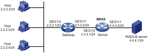
Procedure
1. Configure the RADIUS server: (This section uses the Linux Free RADIUS server as an example.)
# Add BRAS IP address 4.4.4.2 and secret radius to the clients.conf file.
client 4.4.4.2/32 {
ipaddr = 4.4.4.2
netmask=32
secret=radius
}
# Add the usernames and passwords to the users user information file. The usernames are the host IP addresses and the plaintext password is radius.
2.2.2.2 Cleartext-Password :="radius"
2.2.2.3 Cleartext-Password :="radius"
2.2.2.4 Cleartext-Password :="radius"
2. Configure the BRAS:
a. Configure IP addresses for interfaces. (Details not shown.)
b. Configure a RADIUS scheme:
# Create a RADIUS scheme named rs1 and enter its view.
<Device> system-view
[Device] radius scheme rs1
# Configure primary servers and keys for authentication and accounting.
[Device-radius-rs1] primary authentication 4.4.4.1
[Device-radius-rs1] primary accounting 4.4.4.1
[Device-radius-rs1] key authentication simple radius
[Device-radius-rs1] key accounting simple radius
# Exclude the ISP name from the username sent to the RADIUS server.
[Device-radius-rs1] user-name-format without-domain
[Device-radius-rs1] quit
c. Configure the ISP domain:
# Create an ISP domain named dm1 and enter its view.
[Device] domain name dm1
# Configure dm1 to use RADIUS scheme rs1.
[Device-isp-dm1] authentication ipoe radius-scheme rs1
[Device-isp-dm1] authorization ipoe radius-scheme rs1
[Device-isp-dm1] accounting ipoe radius-scheme rs1
[Device-isp-dm1] quit
d. Configure IPoE:
# Enable IPoE and configure Layer 3 access mode on GigabitEthernet 3/1/2.
[Device] interface gigabitethernet 3/1/2
[Device–GigabitEthernet3/1/2] ip subscriber routed enable
# Enable unclassified-IP packet initiation on GigabitEthernet 3/1/2.
[Device–GigabitEthernet3/1/2] ip subscriber initiator unclassified-ip enable
# Specify dm1 as the ISP domain for unclassified-IP users.
[Device–GigabitEthernet3/1/2] ip subscriber unclassified-ip domain dm1
# Configure plaintext password radius for authentication.
[Device–GigabitEthernet3/1/2] ip subscriber password plaintext radius
# Configure online detection:
- Use ICMP detection mode.
- Set the maximum number of detection attempts to 2.
- Set the detection interval to 30 seconds.
[Device–GigabitEthernet3/1/2] ip subscriber user-detect ip icmp retry 2 interval 30
[Device–GigabitEthernet3/1/2] quit
Verifying the configuration
Use the display ip subscriber session command to verify that the BRAS deletes the IPoE session after the user goes offline.
Example: Configuring IPoE common Web authentication for static users
Network configuration
As shown in Figure 22, the host accesses the BRAS though a Layer 2 device. The BRAS performs AAA for the host through the RADIUS server. A server installed with H3C IMC acts as the RADIUS server, the portal authentication server, and the portal Web server. The FTP server is an internal network server.
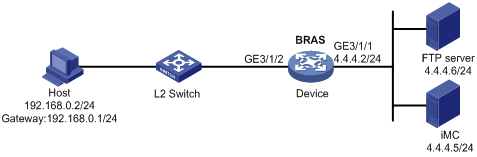
Procedure
1. Configure the BRAS:
a. Configure IP addresses for interfaces. (Details not shown.)
b. Configure the IP address of the portal authentication server newpt as 4.4.4.5 and the plaintext key 123456.
[Device] portal server newpt
[Device-portal-server-newpt] ip 4.4.4.5 key simple 123456
[Device-portal-server-newpt] quit
c. Specify 11111 as the HTTPS redirect listening port number.
[Device] http-redirect https-port 11111
d. Create a local user group named web.
[Device] user-group web
New user group added.
[Device-ugroup-web] quit
e. Configure ACLs for preauthentication:
# Create an IPv4 advanced ACL named web_permit. Configure a rule to permit all packets destined for the portal server from users in user group web.
[Device] acl advanced name web_permit
[Device-acl-ipv4-adv-web_permit] rule 0 permit ip destination 4.4.4.5 0 user-group web
[Device-acl-ipv4-adv-web_permit] quit
# Create an IPv4 advanced ACL named neiwang. Configure a rule to permit all packets destined for the internal network server from users in user group web.
[Device] acl advanced name neiwang
[Device-acl-ipv4-adv-neiwang] rule 0 permit ip destination 4.4.4.6 0 user-group web
[Device-acl-ipv4-adv-neiwang] quit
# Create an IPv4 advanced ACL named web_http. Configure a rule to permit TCP packets with the destination port 80 (HTTP packets) from users in user group web.
[Device] acl advanced name web_http
[Device-acl-ipv4-adv-web_http] rule 0 permit tcp destination-port eq www user-group web
[Device-acl-ipv4-adv-web_http] quit
# Create an IPv4 advanced ACL named web_https, and configure a rule to permit TCP packets with the destination port 443 (HTTPS packets) from users in user group web.
[Device] acl advanced name web_https
[Device-acl-ipv4-adv-web_https] rule 0 permit tcp destination-port eq 443 user-group web
[Device-acl-ipv4-adv-web_https] quit
# Create an IPv4 advanced ACL named ip, and configure a rule to permit IP packets from users in user group web.
[Device] acl advanced name ip
[Device-acl-ipv4-adv-ip] rule 0 permit ip user-group web
[Device-acl-ipv4-adv-ip] quit
# Create an IPv4 advanced ACL named neiwang_out, and configure a rule to permit IP packets from the internal network server in user group web.
[Device] acl advanced name neiwang_out
[Device-acl-ipv4-adv-neiwang_out] rule 0 permit ip source 4.4.4.6 0 user-group web
[Device-acl-ipv4-adv-neiwang_out] quit
# Create an IPv4 advanced ACL named web_out, and configure a rule to permit IP packets from the portal server in user group web.
[Device] acl advanced name web_out
[Device-acl-ipv4-adv-web_out] rule 0 permit ip source 4.4.4.5 0 user-group web
[Device-acl-ipv4-adv-web_out] quit
f. Configure QoS traffic classes for preauthentication users:
# Create the traffic class web_permit and specify ACL web_permit as the match criterion.
[Device] traffic classifier web_permit operator and
[Device-classifier-web_permit] if-match acl name web_permit
[Device-classifier-web_permit] quit
# Create the traffic class neiwang and specify ACL neiwang as the match criterion.
[Device] traffic classifier neiwang operator and
[Device-classifier-neiwang] if-match acl name neiwang
[Device-classifier-neiwang] quit
# Create the traffic class web_http and specify ACL web_http as the match criterion.
[Device] traffic classifier web_http operator and
[Device-classifier-web_http] if-match acl name web_http
[Device-classifier-web_http] quit
# Create the traffic class web_https and specify ACL web_https as the match criterion.
[Device] traffic classifier web_https operator and
[Device-classifier-web_https] if-match acl name web_https
[Device-classifier-web_https] quit
# Create the traffic class web_deny and specify ACL ip as the match criterion.
[Device] traffic classifier web_deny operator and
[Device-classifier-web_deny] if-match acl name ip
[Device-classifier-web_deny] quit
# Create the traffic class neiwang_out and specify ACL neiwang_out as the match criterion.
[Device] traffic classifier neiwang_out operator and
[Device-classifier-neiwang_out] if-match acl name neiwang_out
[Device-classifier-neiwang_out] quit
# Create the traffic class web_out and specify ACL web_out as the match criterion.
[Device] traffic classifier web_out operator and
[Device-classifier-web_out] if-match acl name web_out
[Device-classifier-web_out] quit
g. Configure QoS traffic behaviors:
# Configure the traffic behavior web_permit to permit traffic to pass through without rate limiting or accounting.
[Device] traffic behavior web_permit
[Device-behavior-web_permit] filter permit
[Device-behavior-web_permit] free account
[Device-behavior-web_permit] quit
# Configure the traffic behavior neiwang to permit traffic to pass through.
[Device] traffic behavior neiwang
[Device-behavior-neiwang] filter permit
[Device-behavior-neiwang] quit
# Configure the traffic behavior web_http to redirect HTTP packets to the CPU.
[Device] traffic behavior web_http
[Device-behavior-web_http] redirect http-to-cpu
[Device-behavior-web_http] quit
# Configure the traffic behavior web_https to redirect HTTPS packets to the CPU.
[Device] traffic behavior web_https
[Device-behavior-web_https] redirect https-to-cpu
[Device-behavior-web_https] quit
# Configure the traffic behavior web_deny to deny traffic.
[Device] traffic behavior web_deny
[Device-behavior-web_deny] filter deny
[Device-behavior-web_deny] free account
[Device-behavior-web_deny] quit
# Configure the traffic behavior neiwang_out to permit traffic to pass through.
[Device] traffic behavior neiwang_out
[Device-behavior-neiwang_out] filter permit
[Device-behavior-neiwang_out] quit
# Configure the traffic behavior web_out to permit traffic without rate limiting or traffic accounting.
[Device] traffic behavior web_out
[Device-behavior-web_out] filter permit
[Device-behavior-web_out] free account
[Device-behavior-web_out] quit
h. Configure the QoS policies:
# Create a QoS policy named web.
[Device] qos policy web
# Associate the traffic class web_permit with the traffic behavior web_permit.
[Device-qospolicy-web] classifier web_permit behavior web_permit
# Associate the traffic class neiwang with the traffic behavior neiwang.
[Device-qospolicy-web] classifier neiwang behavior neiwang
# Associate the traffic class web_http with the traffic behavior web_http.
[Device-qospolicy-web] classifier web_http behavior web_http
# Associate the traffic class web_https with the traffic behavior web_https.
[Device-qospolicy-web] classifier web_https behavior web_https
# Associate the traffic class web_deny with the traffic behavior web_deny.
[Device-qospolicy-web] classifier web_deny behavior web_deny
[Device-qospolicy-web] quit
# Configure a QoS policy named out.
[Device] qos policy out
# Associate the traffic class web_out with the traffic behavior web_out. Associate the traffic class neiwang_out with the traffic behavior neiwang_out. Associate the traffic class web_deny with the traffic behavior web_deny.
[Device-qospolicy-out] classifier web_out behavior web_out
[Device-qospolicy-out] classifier neiwang_out behavior neiwang_out
[Device-qospolicy-out] classifier web_deny behavior web_deny
[Device-qospolicy-out] quit
i. Apply the QoS policies:
# Apply the QoS Policy web to the inbound traffic globally.
[Device] qos apply policy web global inbound
# Apply the QoS Policy out to the outbound traffic globally.
[Device] qos apply policy out global outbound
j. Configure a RADIUS scheme:
# Create a RADIUS scheme named rs1 and enter its view.
[Device] radius scheme rs1
# Configure primary servers and keys for authentication and accounting.
[Device-radius-rs1] primary authentication 4.4.4.5
[Device-radius-rs1] primary accounting 4.4.4.5
[Device-radius-rs1] key authentication simple radius
[Device-radius-rs1] key accounting simple radius
# Exclude the ISP name from the username sent to the RADIUS server.
[Device-radius-rs1] user-name-format without-domain
[Device-radius-rs1] quit
k. Configure the preauthentication ISP domain and Web authentication ISP domain:
# Configure the ISP domain dm1 for IPoE user preauthentication.
[Device] domain name dm1
[Device-isp-dm1] authentication ipoe none
[Device-isp-dm1] authorization ipoe none
[Device-isp-dm1] accounting ipoe none
# Configure the authorized user group in ISP domain dm1.
[Device-isp-dm1] authorization-attribute user-group web
# Configure the Web authentication page URL and Web authentication server IP address in ISP domain dm1.
[Device-isp-dm1] web-server url http://4.4.4.5:8080/portal/
[Device-isp-dm1] web-server ip 4.4.4.5
[Device-isp-dm1] quit
# Configure the ISP domain dm2 for IPoE user Web authentication.
[Device] domain name dm2
[Device-isp-dm2] authentication ipoe radius-scheme rs1
[Device-isp-dm2] authorization ipoe radius-scheme rs1
[Device-isp-dm2] accounting ipoe radius-scheme rs1
[Device-isp-dm2] quit
l. Configure the gateway for users.
# Enable DHCP globally.
[Device] dhcp enable
# Create address pool pool1, and specify the user gateway address as 192.168.0.1.
[Device] dhcp server ip-pool pool1
[Device-dhcp-pool-pool1] gateway-list 192.168.0.1 export-route
[Device-dhcp-pool-pool1] quit
m. Configure IPoE:
# Enable IPoE and configure Layer 2 access mode on GigabitEthernet 3/1/2.
[Device] interface gigabitethernet 3/1/2
[Device–GigabitEthernet3/1/2] ip subscriber l2-connected enable
# Enable unclassified-IPv4 packet initiation.
[Device–GigabitEthernet3/1/2] ip subscriber initiator unclassified-ip enable matching-user
# Configure a static IPoE user.
[Device–GigabitEthernet3/1/2] ip subscriber session static ip 192.168.0.2
# Configure Web authentication for IPoE users on GigabitEthernet 3/1/2.
[Device–GigabitEthernet3/1/2] ip subscriber authentication-method web
The operation may cut all users on this interface. Continue?[Y/N]:y
# Configure the ISP domain dm1 for preauthentication and the ISP domain dm2 for Web authentication on GigabitEthernet 3/1/2.
[Device–GigabitEthernet3/1/2] ip subscriber pre-auth domain dm1
[Device–GigabitEthernet3/1/2] ip subscriber web-auth domain dm2
[Device–GigabitEthernet3/1/2] quit
2. Configure the RADIUS server:
a. Configure the access device:
i Log in to the IMC platform and click the User tab.
ii Select User Access Policy > Access Device Management > Access Device from the navigation tree to open the access device configuration page.
iii Click Add to open the page as shown in Figure 23.
iv Enter the shared key radius.
v Use the default settings for other parameters.
Figure 23 Adding an access device
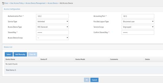
vi Click Add Manually in the Device List area to open the page as shown in Figure 24.
vii Enter the access device's IP address 4.4.4.2.
viii Click OK.
Figure 24 Manually adding an access device
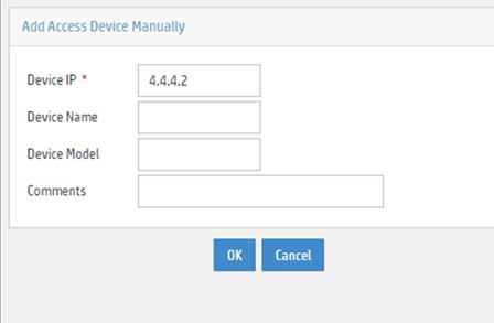
a. Add an access policy:
i Select User Access Policy > Access Policy from the navigation tree to open the access policy page.
ii Click Add to open the page as shown in Figure 25.
iii Enter the access policy name AccessPolicy.
iv Use the default settings for other parameters.
Figure 25 Adding an access policy
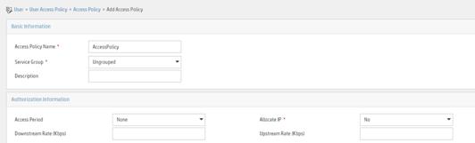
a. Add an access service:
i Select User Access Policy > Access Service from the navigation tree to open the access service page.
ii Click Add to open the page as shown in Figure 26.
iii Enter the service name IPoE_Server.
iv Select AccessPolicy from the default access policy list.
v Use the default settings for other parameters.
Figure 26 Adding an access service
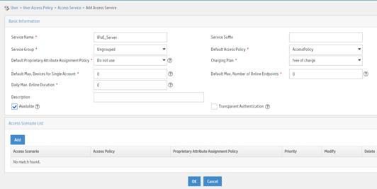
a. Add a user:
i Select User Management > Add User from the navigation tree to open the adding user page, as shown in Figure 27.
ii Enter the username IPoE_Web001 and the user ID 001.
iii Click OK.

a. Add an access user:
i Select Access User > All Access Users from the navigation tree to open the access user page.
ii Click Add to open the page as shown in Figure 28.
iii Select IPoE_Web001 for the username.
iv Enter the account name user1.
v Enter the password pass1.
vi Select the access service IPoE_Server.
Figure 28 Adding an access user
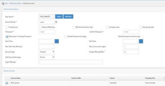
3. Configure the portal server:
a. Configure the portal homepage:
i Select User Access Policy > Portal Service > Server from the navigation tree to open the portal server configuration page, as shown in Figure 29.
ii Click OK.
Figure 29 Portal server configuration page
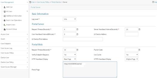
a. Configure portal authentication source IP address range:
i Select User Access Policy > Portal Service > IP Group from the navigation tree to open the portal IP address group configuration page.
ii Click Add to open the page as shown in Figure 30.
iii Enter the IP group name IPoE_Web_User.
iv Enter the start IP address (192.168.0.1) and end IP address (192.168.0.255) of the IP group. Make sure the host IP address is in the IP group.
v Click OK.
Figure 30 Adding an IP address group

a. Add a portal device:
i Select User Access Policy > Portal Service > Device from the navigation tree to open the portal device configuration page.
ii Click Add to open the page as shown in Figure 31.
iii Enter the device name NAS.
iv Enter the IP address of the portal packets' outgoing interface GigabitEthernet 3/1/1 (4.4.4.2).
v Enter the key 123456.
vi Select Directly Connect for access method.
vii Click OK.
Figure 31 Adding a portal device

a. Associate the portal device with the IP address group:
i Click the icon in the Port Group Information Management column of device NAS to open the port group configuration page, as shown in Figure 32.
ii Click Add to open the page as shown in Figure 33.
iii Enter the port group name group.
iv Select the configured IP address group IPoE_Web_User. Make sure the IP address used by the user to access the network is within this IP address group.
v Click OK.

Figure 33 Port group configuration
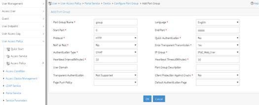
Verifying the configuration
# Display IPoE session information to verify that the host has passed preauthentication.
[Device] display ip subscriber session verbose
Basic:
Description : -
Username : 192.168.0.2
Domain : dm1
VPN instance : N/A
IP address : 192.168.0.2
User address type : N/A
MAC address : 0015-e947-f4d4
Service-VLAN/Customer-VLAN : -/-
Access interface : GE3/1/2
User ID : 0x3808001c
VPI/VCI(for ATM) : -/-
VSI Index : -
VSI link ID : -
VXLAN ID : -
DNS servers : 8.8.8.8
IPv6 DNS servers : N/A
DHCP lease : N/A
DHCP remain lease : N/A
Access time : Aug 2 16:51:28 2016
Online time(hh:mm:ss) : 00:00:20
Service node : Slot 3 CPU 0
Authentication type : Web pre-auth
IPv4 access type : Static
IPv4 detect state : Detecting
State : Online
AAA:
ITA policy name : N/A
IP pool : N/A
IPv6 pool : N/A
Primary DNS server : N/A
Secondary DNS server : N/A
Primary IPv6 DNS server : N/A
Secondary IPv6 DNS server : N/A
Session idle cut : N/A
Session duration : N/A, remaining: N/A
Traffic quota : N/A
Traffic remained : N/A
Acct start-fail action : Online
Acct update-fail action : Online
Acct quota-out action : Offline
Dual-stack accounting mode : Merge
Max IPv4 multicast addresses: 4
IPv4 multicast address list : N/A
Max IPv6 multicast addresses: 4
IPv6 multicast address list : N/A
Accounting start time : Aug 2 16:51:28 2016
Redirect URL : http://4.4.4.5:8080/portal/
Subscriber ID : -
QoS:
User profile : N/A
Session group profile : N/A
User group ACL : web (active)
Inbound CAR : N/A
Outbound CAR : N/A
Inbound user priority : N/A
Outbound user priority : N/A
Flow statistic:
Uplink packets/bytes : 0/0
Downlink packets/bytes : 0/0
IPv6 uplink packets/bytes : 0/0
IPv6 downlink packets/bytes : 0/0
As shown in Figure 34, the Web login page opens after preauthentication. Enter the username and password on the page.

# Display IPoE session information to verify that the host has passed Web authentication and come online.
[Device] display ip subscriber session verbose
Basic:
Description : -
Username : user1
Domain : dm2
VPN instance : N/A
IP address : 192.168.0.2
User address type : N/A
MAC address : 0015-e947-f4d4
Service-VLAN/Customer-VLAN : -/-
Access interface : GE3/1/2
User ID : 0x3808001c
VPI/VCI(for ATM) : -/-
VSI Index : -
VSI link ID : -
VXLAN ID : -
DNS servers : 8.8.8.8
IPv6 DNS servers : N/A
DHCP lease : N/A
DHCP remain lease : N/A
Access time : Aug 2 16:52:28 2016
Online time(hh:mm:ss) : 00:00:20
Service node : Slot 3 CPU 0
Authentication type : Web
IPv4 access type : Static
IPv4 detect state : Detecting
State : Online
AAA:
ITA policy name : N/A
IP pool : N/A
IPv6 pool : N/A
Primary DNS server : N/A
Secondary DNS server : N/A
Primary IPv6 DNS server : N/A
Secondary IPv6 DNS server : N/A
Session idle cut : N/A
Session duration : N/A, remaining: N/A
Traffic quota : N/A
Traffic remained : N/A
Acct start-fail action : Online
Acct update-fail action : Online
Acct quota-out action : Offline
Dual-stack accounting mode : Merge
Max IPv4 multicast addresses: 4
IPv4 multicast address list : N/A
Max IPv6 multicast addresses: 4
IPv6 multicast address list : N/A
Accounting start time : Aug 2 16:52:28 2016
Subscriber ID : -
QoS:
User profile : N/A
Session group profile : N/A
User group ACL : N/A
Inbound CAR : N/A
Outbound CAR : N/A
Inbound user priority : N/A
Outbound user priority : N/A
Flow statistic:
Uplink packets/bytes : 0/0
Downlink packets/bytes : 0/0
IPv6 uplink packets/bytes : 0/0
IPv6 downlink packets/bytes : 0/0
Example: Configuring IPoE common Web authentication for DHCPv4 users
Network configuration
As shown in Figure 35, the host accesses the BRAS as a DHCP client though a Layer 2 device. It obtains configuration information from the DHCP server through the BRAS. The BRAS performs AAA for the host through the RADIUS server. A server installed with H3C IMC acts as the RADIUS server, the portal authentication server, and the portal Web server. The FTP server is an internal network server.
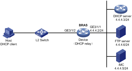
Procedure
1. Configure the DHCP server:
# Enable DHCP.
<DHCP-server> system-view
[DHCP-server] dhcp enable
# Create an IP address pool named pool1 and enter its view.
[DHCP-server] dhcp server ip-pool pool1
# Specify primary subnet 192.168.0.0/24 for dynamic allocation in DHCP address pool pool1.
[DHCP-server-dhcp-pool-pool1] network 192.168.0.0 24
# Specify gateway address 192.168.0.1 in DHCP address pool pool1.
[DHCP-server-dhcp-pool-pool1] gateway-list 192.168.0.1
# Specify DNS server address 8.8.8.8 in DHCP address pool pool1.
[DHCP-server-dhcp-pool-pool1] dns-list 8.8.8.8
# Exclude IP address 192.168.0.1 from dynamic allocation in DHCP address pool pool1.
[DHCP-server-dhcp-pool-pool1] forbidden-ip 192.168.0.1
[DHCP-server-dhcp-pool-pool1] quit
# Configure a static route to specify the next hop of DHCP replies destined to network segment 192.168.0.0 as the IP address of the interface connected to the DHCP client, 4.4.4.2.
[DHCP-server] ip route-static 192.168.0.0 24 4.4.4.2
2. Configure the BRAS:
a. Configure IP addresses for interfaces. (Details not shown.)
b. Configure the DHCP relay agent:
# Enable DHCP.
<Device> system-view
[Device] dhcp enable
# Enable the DHCP relay agent to record client information in relay entries.
[Device] dhcp relay client-information record
# Disable the DHCP relay agent from periodically refreshing dynamic relay entries.
[Device] undo dhcp relay client-information refresh enable
# Enable DHCP server proxy on the DHCP relay agent on GigabitEthernet 3/1/2.
[Device] interface gigabitethernet 3/1/2
[Device–GigabitEthernet3/1/2] dhcp select relay proxy
[Device–GigabitEthernet3/1/2] quit
# Create an IP address pool named pool1 for the DHCP relay agent.
[Device] dhcp server ip-pool pool1
# Specify gateway address 192.168.0.1 in DHCP address pool pool1.
[Device-dhcp-pool-pool1] gateway-list 192.168.0.1 export-route
# Specify DHCP server 4.4.4.3 in DHCP address pool pool1.
[Device-dhcp-pool-pool1] remote-server 4.4.4.3
[Device-dhcp-pool-pool1] quit
c. Configure the IP address of the portal authentication server newpt as 4.4.4.5 and the plaintext key 123456.
[Device] portal server newpt
[Device-portal-server-newpt] ip 4.4.4.5 key simple 123456
[Device-portal-server-newpt] quit
d. Specify 11111 as the HTTPS redirect listening port number.
[Device] http-redirect https-port 11111
e. Create a local user group named web.
[Device] user-group web
New user group added.
[Device-ugroup-web] quit
f. Configure ACLs for preauthentication:
# Create an IPv4 advanced ACL named web_permit. Configure a rule to permit all packets destined for the portal server from users in user group web.
[Device] acl advanced name web_permit
[Device-acl-ipv4-adv-web_permit] rule 0 permit ip destination 4.4.4.5 0 user-group web
[Device-acl-ipv4-adv-web_permit] quit
# Create an IPv4 advanced ACL named neiwang. Configure a rule to permit all packets destined for the internal network server from users in user group web.
[Device] acl advanced name neiwang
[Device-acl-ipv4-adv-neiwang] rule 0 permit ip destination 4.4.4.6 0 user-group web
[Device-acl-ipv4-adv-neiwang] quit
# Create an IPv4 advanced ACL named web_http. Configure a rule to permit TCP packets with the destination port 80 (HTTP packets) from users in user group web.
[Device] acl advanced name web_http
[Device-acl-ipv4-adv-web_http] rule 0 permit tcp destination-port eq www user-group web
[Device-acl-ipv4-adv-web_http] quit
# Create an IPv4 advanced ACL named web_https, and configure a rule to permit TCP packets with the destination port 443 (HTTPS packets) from users in user group web.
[Device] acl advanced name web_https
[Device-acl-ipv4-adv-web_https] rule 0 permit tcp destination-port eq 443 user-group web
[Device-acl-ipv4-adv-web_https] quit
# Create an IPv4 advanced ACL named ip, and configure a rule to permit IP packets from users in user group web.
[Device] acl advanced name ip
[Device-acl-ipv4-adv-ip] rule 0 permit ip user-group web
[Device-acl-ipv4-adv-ip] quit
# Create an IPv4 advanced ACL named neiwang_out, and configure a rule to permit IP packets from the internal network server in user group web.
[Device] acl advanced name neiwang_out
[Device-acl-ipv4-adv-neiwang_out] rule 0 permit ip source 4.4.4.6 0 user-group web
[Device-acl-ipv4-adv-neiwang_out] quit
# Create an IPv4 advanced ACL named web_out, and configure a rule to permit IP packets from the portal server in user group web.
[Device] acl advanced name web_out
[Device-acl-ipv4-adv-web_out] rule 0 permit ip source 4.4.4.5 0 user-group web
[Device-acl-ipv4-adv-web_out] quit
g. Configure QoS traffic classes for preauthentication users:
# Create the traffic class web_permit and specify ACL web_permit as the match criterion.
[Device] traffic classifier web_permit operator and
[Device-classifier-web_permit] if-match acl name web_permit
[Device-classifier-web_permit] quit
# Create the traffic class neiwang and specify ACL neiwang as the match criterion.
[Device] traffic classifier neiwang operator and
[Device-classifier-neiwang] if-match acl name neiwang
[Device-classifier-neiwang] quit
# Create the traffic class web_http and specify ACL web_http as the match criterion.
[Device] traffic classifier web_http operator and
[Device-classifier-web_http] if-match acl name web_http
[Device-classifier-web_http] quit
# Create the traffic class web_https and specify ACL web_https as the match criterion.
[Device] traffic classifier web_https operator and
[Device-classifier-web_https] if-match acl name web_https
[Device-classifier-web_https] quit
# Create the traffic class web_deny and specify ACL ip as the match criterion.
[Device] traffic classifier web_deny operator and
[Device-classifier-web_deny] if-match acl name ip
[Device-classifier-web_deny] quit
# Create the traffic class neiwang_out and specify ACL neiwang_out as the match criterion.
[Device] traffic classifier neiwang_out operator and
[Device-classifier-neiwang_out] if-match acl name neiwang_out
[Device-classifier-neiwang_out] quit
# Create the traffic class web_out and specify ACL web_out as the match criterion.
[Device] traffic classifier web_out operator and
[Device-classifier-web_out] if-match acl name web_out
[Device-classifier-web_out] quit
h. Configure QoS traffic behaviors:
# Configure the traffic behavior web_permit to permit traffic to pass through without rate limiting or accounting.
[Device] traffic behavior web_permit
[Device-behavior-web_permit] filter permit
[Device-behavior-web_permit] free account
[Device-behavior-web_permit] quit
# Configure the traffic behavior neiwang to permit traffic to pass through.
[Device] traffic behavior neiwang
[Device-behavior-neiwang] filter permit
[Device-behavior-neiwang] quit
# Configure the traffic behavior web_http to redirect HTTP packets to the CPU.
[Device] traffic behavior web_http
[Device-behavior-web_http] redirect http-to-cpu
[Device-behavior-web_http] quit
# Configure the traffic behavior web_https to redirect HTTPS packets to the CPU.
[Device] traffic behavior web_https
[Device-behavior-web_https] redirect https-to-cpu
[Device-behavior-web_https] quit
# Configure the traffic behavior web_deny to deny traffic.
[Device] traffic behavior web_deny
[Device-behavior-web_deny] filter deny
[Device-behavior-web_deny] free account
[Device-behavior-web_deny] quit
# Configure the traffic behavior neiwang_out to permit traffic to pass through.
[Device] traffic behavior neiwang_out
[Device-behavior-neiwang_out] filter permit
[Device-behavior-neiwang_out] quit
# Configure the traffic behavior web_out to permit traffic without rate limiting or traffic accounting.
[Device] traffic behavior web_out
[Device-behavior-web_out] filter permit
[Device-behavior-web_out] free account
[Device-behavior-web_out] quit
i. Configure the QoS policies:
# Create a QoS policy named web.
[Device] qos policy web
# Associate the traffic class web_permit with the traffic behavior web_permit.
[Device-qospolicy-web] classifier web_permit behavior web_permit
# Associate the traffic class neiwang with the traffic behavior neiwang.
[Device-qospolicy-web] classifier neiwang behavior neiwang
# Associate the traffic class web_http with the traffic behavior web_http.
[Device-qospolicy-web] classifier web_http behavior web_http
# Associate the traffic class web_https with the traffic behavior web_https.
[Device-qospolicy-web] classifier web_https behavior web_https
# Associate the traffic class web_deny with the traffic behavior web_deny.
[Device-qospolicy-web] classifier web_deny behavior web_deny
[Device-qospolicy-web] quit
# Configure a QoS policy named out.
[Device] qos policy out
# Associate the traffic class web_out with the traffic behavior web_out. Associate the traffic class neiwang_out with the traffic behavior neiwang_out. Associate the traffic class web_deny with the traffic behavior web_deny.
[Device-qospolicy-out] classifier web_out behavior web_out
[Device-qospolicy-out] classifier neiwang_out behavior neiwang_out
[Device-qospolicy-out] classifier web_deny behavior web_deny
[Device-qospolicy-out] quit
j. Apply the QoS policies:
# Apply the QoS Policy web to the inbound traffic globally.
[Device] qos apply policy web global inbound
# Apply the QoS Policy out to the outbound traffic globally.
[Device] qos apply policy out global outbound
k. Configure a RADIUS scheme:
# Create a RADIUS scheme named rs1 and enter its view.
[Device] radius scheme rs1
# Configure primary servers and keys for authentication and accounting.
[Device-radius-rs1] primary authentication 4.4.4.5
[Device-radius-rs1] primary accounting 4.4.4.5
[Device-radius-rs1] key authentication simple radius
[Device-radius-rs1] key accounting simple radius
# Exclude the ISP name from the username sent to the RADIUS server.
[Device-radius-rs1] user-name-format without-domain
[Device-radius-rs1] quit
l. Configure the preauthentication ISP domain and Web authentication ISP domain:
# Configure the ISP domain dm1 for IPoE user preauthentication.
[Device] domain name dm1
[Device-isp-dm1] authentication ipoe none
[Device-isp-dm1] authorization ipoe none
[Device-isp-dm1] accounting ipoe none
# Configure the authorized IP address pool and user group in preauthentication ISP domain dm1.
[Device-isp-dm1] authorization-attribute user-group web
[Device-isp-dm1] authorization-attribute ip-pool pool1
# Configure the Web authentication page URL in ISP domain dm1.
[Device-isp-dm1] web-server url http://4.4.4.5:8080/portal/
[Device-isp-dm1] quit
# Configure the ISP domain dm2 for IPoE user Web authentication.
[Device] domain name dm2
[Device-isp-dm2] authentication ipoe radius-scheme rs1
[Device-isp-dm2] authorization ipoe radius-scheme rs1
[Device-isp-dm2] accounting ipoe radius-scheme rs1
[Device-isp-dm2] quit
m. Configure IPoE:
# Enable IPoE and configure Layer 2 access mode on GigabitEthernet 3/1/2.
[Device] interface gigabitethernet 3/1/2
[Device–GigabitEthernet3/1/2] ip subscriber l2-connected enable
# Configure Web authentication for IPoE users on GigabitEthernet 3/1/2.
[Device–GigabitEthernet3/1/2] ip subscriber authentication-method web
The operation may cut all users on this interface. Continue?[Y/N]:y
# Configure the ISP domain dm1 for preauthentication and the ISP domain dm2 for Web authentication on GigabitEthernet 3/1/2.
[Device–GigabitEthernet3/1/2] ip subscriber pre-auth domain dm1
[Device–GigabitEthernet3/1/2] ip subscriber web-auth domain dm2
[Device–GigabitEthernet3/1/2] quit
3. Configure the RADIUS server:
a. Configure the access device:
i Log in to the IMC platform and click the User tab.
ii Select User Access Policy > Access Device Management > Access Device from the navigation tree to open the access device configuration page.
iii Click Add to open the page as shown in Figure 36.
iv Enter the shared key radius.
v Use the default settings for other parameters.
Figure 36 Adding an access device
vi Click Add Manually in the Device List area to open the page as shown in Figure 37.
vii Enter the access device's IP address 4.4.4.2.
viii Click OK.
Figure 37 Manually adding an access device
a. Add an access policy:
i Select User Access Policy > Access Policy from the navigation tree to open the access policy page.
ii Click Add to open the page as shown in Figure 38.
iii Enter the access policy name AccessPolicy.
iv Use the default settings for other parameters.
Figure 38 Adding an access policy
a. Add an access service:
i Select User Access Policy > Access Service from the navigation tree to open the access service page.
ii Click Add to open the page as shown in Figure 39.
iii Enter the service name IPoE_Server.
iv Select AccessPolicy from the default access policy list.
v Use the default settings for other parameters.
Figure 39 Adding an access service
a. Add a user:
i Select User Management > Add User from the navigation tree to open the adding user page, as shown in Figure 40.
ii Enter the username IPoE_Web001 and the user ID 001.
iii Click OK.
a. Add an access user:
i Select Access User > All Access Users from the navigation tree to open the access user page.
ii Click Add to open the page as shown in Figure 41.
iii Select IPoE_Web001 for the username.
iv Enter the account name user1.
v Enter the password pass1.
vi Select the access service IPoE_Server.
Figure 41 Adding an access user
4. Configure the portal server:
a. Configure the portal homepage:
i Select User Access Policy > Portal Service > Server from the navigation tree to open the portal server configuration page, as shown in Figure 42.
ii Click OK.
Figure 42 Portal server configuration page
a. Configure portal authentication source IP address range:
i Select User Access Policy > Portal Service > IP Group from the navigation tree to open the portal IP address group configuration page.
ii Click Add to open the page as shown in Figure 43.
iii Enter the IP group name IPoE_Web_User.
iv Enter the start IP address (192.168.0.1) and end IP address (192.168.0.255) of the IP group. Make sure the host IP address is in the IP group.
v Click OK.
Figure 43 Adding an IP address group
a. Add a portal device:
i Select User Access Policy > Portal Service > Device from the navigation tree to open the portal device configuration page.
ii Click Add to open the page as shown in Figure 44.
iii Enter the device name NAS.
iv Enter the IP address of the portal packets' outgoing interface GigabitEthernet 3/1/1 (4.4.4.2).
v Enter the key 123456.
vi Select Directly Connect for access method.
vii Click OK.
Figure 44 Adding a portal device
a. Associate the portal device with the IP address group:
i Click the icon in the Port Group Information Management column of device NAS to open the port group configuration page, as shown in Figure 45.
ii Click Add to open the page as shown in Figure 46.
iii Enter the port group name group.
iv Select the configured IP address group IPoE_Web_User. Make sure the IP address used by the user to access the network is within this IP address group.
v Click OK.
Figure 46 Port group configuration
Verifying the configuration
# Display IPoE session information to verify that the host has passed preauthentication.
[Device] display ip subscriber session verbose
Basic:
Description : -
Username : 0015e947f4d4
Domain : dm1
VPN instance : N/A
IP address : 192.168.0.2
User address type : N/A
MAC address : 0015-e947-f4d4
Service-VLAN/Customer-VLAN : -/-
Access interface : GE3/1/2
User ID : 0x3808001c
VPI/VCI(for ATM) : -/-
VSI Index : -
VSI link ID : -
VXLAN ID : -
DNS servers : 8.8.8.8
IPv6 DNS servers : N/A
DHCP lease : 86400 sec
DHCP remain lease : 86380 sec
Access time : Aug 2 16:51:28 2016
Online time(hh:mm:ss) : 00:00:20
Service node : Slot 3 CPU 0
Authentication type : Web pre-auth
IPv4 access type : DHCP
IPv4 detect state : Detecting
State : Online
AAA:
ITA policy name : N/A
IP pool : pool1
IPv6 pool : N/A
Primary DNS server : N/A
Secondary DNS server : N/A
Primary IPv6 DNS server : N/A
Secondary IPv6 DNS server : N/A
Session idle cut : N/A
Session duration : N/A, remaining: N/A
Traffic quota : N/A
Traffic remained : N/A
Acct start-fail action : Online
Acct update-fail action : Online
Acct quota-out action : Offline
Dual-stack accounting mode : Merge
Max IPv4 multicast addresses: 4
IPv4 multicast address list : N/A
Max IPv6 multicast addresses: 4
IPv6 multicast address list : N/A
Accounting start time : Aug 2 16:51:28 2016
Redirect URL : http://4.4.4.5:8080/portal/
Subscriber ID : -
QoS:
User profile : N/A
Session group profile : N/A
User group ACL : web (active)
Inbound CAR : N/A
Outbound CAR : N/A
Inbound user priority : N/A
Outbound user priority : N/A
Flow statistic:
Uplink packets/bytes : 0/0
Downlink packets/bytes : 0/0
IPv6 uplink packets/bytes : 0/0
IPv6 downlink packets/bytes : 0/0
As shown in Figure 47, the Web login page opens after preauthentication. Enter the username and password on the page.
# Display IPoE session information to verify that the host has passed Web authentication and come online.
[Device] display ip subscriber session verbose
Basic:
Description : -
Username : user1
Domain : dm2
VPN instance : N/A
IP address : 192.168.0.2
User address type : N/A
MAC address : 0015-e947-f4d4
Service-VLAN/Customer-VLAN : -/-
Access interface : GE3/1/2
User ID : 0x3808001c
VPI/VCI(for ATM) : -/-
VSI Index : -
VSI link ID : -
VXLAN ID : -
DNS servers : 8.8.8.8
IPv6 DNS servers : N/A
DHCP lease : 86400 sec
DHCP remain lease : 86380 sec
Access time : Aug 2 16:52:28 2016
Online time(hh:mm:ss) : 00:00:20
Service node : Slot 3 CPU 0
Authentication type : Web mac-trigger
IPv4 access type : DHCP
IPv4 detect state : Detecting
State : Online
AAA:
ITA policy name : N/A
IP pool : pool1
IPv6 pool : N/A
Primary DNS server : N/A
Secondary DNS server : N/A
Primary IPv6 DNS server : N/A
Secondary IPv6 DNS server : N/A
Session idle cut : N/A
Session duration : N/A, remaining: N/A
Traffic quota : N/A
Traffic remained : N/A
Acct start-fail action : Online
Acct update-fail action : Online
Acct quota-out action : Offline
Dual-stack accounting mode : Merge
Max IPv4 multicast addresses: 4
IPv4 multicast address list : N/A
Max IPv6 multicast addresses: 4
IPv6 multicast address list : N/A
Accounting start time : Aug 2 16:52:28 2016
Subscriber ID : -
QoS:
User profile : N/A
Session group profile : N/A
User group ACL : N/A
Inbound CAR : N/A
Outbound CAR : N/A
Inbound user priority : N/A
Outbound user priority : N/A
Flow statistic:
Uplink packets/bytes : 0/0
Downlink packets/bytes : 0/0
IPv6 uplink packets/bytes : 0/0
IPv6 downlink packets/bytes : 0/0
Example: Configuring IPoE common Web authentication for DHCPv6 users
Network configuration
As shown in Figure 48, Router A is a BRAS of a school. Configure the BRAS to provide users in the school with the following IPoE services:
· The host accesses the BRAS as a DHCP client though a Layer 2 device.
· The host obtains configuration information from the DHCP server through the BRAS.
· The BRAS performs AAA for the host through the RADIUS server. A server installed with H3C IMC acts as the RADIUS server, the portal authentication server, and the portal Web server.
· The FTP server is an internal network server.
· Limit the access rate to 5 Mbps for the user after passing Web authentication.
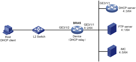
Procedure
1. Configure IP addresses and routes.
As shown in Figure 48, configure IP addresses for interfaces and make sure the BRAS and servers can reach each other at Layer 3. (Details not shown.)
2. Configure the DNS server.
Configure the DNS server properly, so that the server can parse the IPv6 URL corresponding to the Web authentication page http://www.h3c.web.com. (Details not shown.)
3. Configure the DHCP server:
# Create a DHCPv6 address pool named pool1 and enter its view.
<DHCP-server> system-view
[DHCP] ipv6 dhcp pool pool1
# Specify primary subnet 192::0/64 and DNS server address 8::8 for dynamic allocation in DHCPv6 address pool pool1.
[DHCP-dhcp6-pool-pool1] network 192::0/64
[DHCP-dhcp6-pool-pool1] dns-server 8::8
[DHCP-dhcp6-pool-pool1] quit
# Exclude IP address 192::1 from dynamic allocation in DHCPv6 address pool pool1.
[DHCP] ipv6 dhcp server forbidden-address 192::1
# Enable the DHCPv6 server on GigabitEthernet 3/1/1.
[DHCP] interface gigabitethernet 3/1/1
[DHCP-GigabitEthernet3/1/1] ipv6 dhcp select server
[DHCP-GigabitEthernet3/1/1] quit
# Configure a static route to specify the next hop of DHCPv6 replies destined to network segment 192::0 as the IP address of the interface connected to the DHCPv6 client, 4::2.
[DHCP] ipv6 route-static 192::0 64 4::2
4. Configure the BRAS:
a. Configure the DHCP relay agent:
# Create an IP address pool named pool1 for the DHCP relay agent.
<Device> system-view
[Device] ipv6 dhcp pool pool1
# Specify gateway address 192::1 in DHCP address pool pool1.
[Device-dhcp6-pool-pool1] gateway-list 192::1
# Specify DHCP server 4::3 in DHCP address pool pool1.
[Device-dhcp6-pool-pool1] remote-server 4::3
[Device-dhcp6-pool-pool1] quit
# Automatically generate a link-local address for GigabitEthernet 3/1/2.
[Device] interface gigabitethernet 3/1/2
[Device–GigabitEthernet3/1/2] ipv6 address auto link-local
# Enable the DHCPv6 relay agent on GigabitEthernet 3/1/2.
[Device–GigabitEthernet3/1/2] ipv6 dhcp select relay
# Enable recording client information in DHCPv6 relay entries.
[Device–GigabitEthernet3/1/2] ipv6 dhcp relay client-information record
# Disable RA message suppression on GigabitEthernet 3/1/2.
[Device–GigabitEthernet3/1/2] undo ipv6 nd ra halt
# Set the managed address configuration flag (M) to 1 in RA advertisements to be sent. Then, the host uses a DHCPv6 server to obtain IPv6 addresses.
[Device–GigabitEthernet3/1/2] ipv6 nd autoconfig managed-address-flag
# Set the other stateful configuration flag (O) to 1 in RA advertisements to be sent. Then, the host uses a DHCPv6 server to obtain configuration information other than IPv6 addresses.
[Device–GigabitEthernet3/1/2] ipv6 nd autoconfig other-flag
# Disable GigabitEthernet 3/1/2 from advertising the specified prefix in RA messages, preventing the endpoint from obtaining a temporary IPv6 address. In an IPv6 network, an endpoint might use a temporary IPv6 address for IPoE Web authentication, which will cause authentication failure.
[Device–GigabitEthernet3/1/2] ipv6 nd ra prefix 192::/64 no-advertise
[Device–GigabitEthernet3/1/2] quit
b. Configure the IPv6 address of the IPv6 portal authentication server newpt1 as 4::5 and the plaintext key 123456.
[Device] portal server newpt1
[Device-portal-server-newpt1] ipv6 4::5 key simple 123456
[Device-portal-server-newpt1] quit
c. Specify 11111 as the HTTPS redirect listening port number.
[Device] http-redirect https-port 11111
d. Create a local user group named web.
[Device] user-group web
New user group added.
[Device-ugroup-web] quit
e. Configure ACLs for preauthentication:
# Create an IPv6 advanced ACL named web_permit. Configure a rule to permit all packets destined for the portal server from users in user group web.
[Device] acl ipv6 advanced name web_permit
[Device-acl-ipv6-adv-web_permit] rule 0 permit ipv6 destination 4::5 128 user-group web
[Device-acl-ipv6-adv-web_permit] quit
# Create an IPv6 advanced ACL named neiwang. Configure a rule to permit all packets destined for the internal network server from users in user group web.
[Device] acl ipv6 advanced name neiwang
[Device-acl-ipv6-adv-neiwang] rule 0 permit ipv6 destination 4::1 128 user-group web
[Device-acl-ipv6-adv-neiwang] quit
# Create an IPv6 advanced ACL named web_http. Configure a rule to permit TCP packets with the destination port 80 (HTTP packets) from users in user group web.
[Device] acl ipv6 advanced name web_http
[Device-acl-ipv6-adv-web_http] rule 0 permit tcp destination-port eq www user-group web
[Device-acl-ipv6-adv-web_http] quit
# Create an IPv6 advanced ACL named web_https, and configure a rule to permit TCP packets with the destination port 443 (HTTPS packets) from users in user group web.
[Device] acl ipv6 advanced name web_https
[Device-acl-ipv6-adv-web_https] rule 0 permit tcp destination-port eq 443 user-group web
[Device-acl-ipv6-adv-web_https] quit
# Create an IPv6 advanced ACL named ip, and configure a rule to permit IP packets from users in user group web.
[Device] acl ipv6 advanced name ip
[Device-acl-ipv6-adv-ip] rule 0 permit ipv6 user-group web
[Device-acl-ipv6-adv-ip] quit
# Create an IPv6 advanced ACL named neiwang_out, and configure a rule to permit IP packets from the internal network server in user group web.
[Device] acl ipv6 advanced name neiwang_out
[Device-acl-ipv6-adv-neiwang_out] rule 0 permit ipv6 source 4::1 128 user-group web
[Device-acl-ipv6-adv-neiwang_out] quit
# Create an IPv6 advanced ACL named web_out, and configure a rule to permit IP packets from the portal server in user group web.
[Device] acl ipv6 advanced name web_out
[Device-acl-ipv6-adv-web_out] rule 0 permit ipv6 source 4::5 128 user-group web
[Device-acl-ipv6-adv-web_out] quit
f. Configure QoS traffic classes for preauthentication users:
# Create the traffic class web_permit and specify ACL web_permit as the match criterion.
[Device] traffic classifier web_permit operator or
[Device-classifier-web_permit] if-match acl ipv6 name web_permit
[Device-classifier-web_permit] quit
# Create the traffic class neiwang and specify ACL neiwang as the match criterion.
[Device] traffic classifier neiwang operator or
[Device-classifier-neiwang] if-match ipv6 acl name neiwang
[Device-classifier-neiwang] quit
# Create the traffic class web_http and specify ACL web_http as the match criterion.
[Device] traffic classifier web_http operator or
[Device-classifier-web_http] if-match ipv6 acl name web_http
[Device-classifier-web_http] quit
# Create the traffic class web_https and specify ACL web_https as the match criterion.
[Device] traffic classifier web_https operator or
[Device-classifier-web_https] if-match ipv6 acl name web_https
[Device-classifier-web_https] quit
# Create the traffic class web_deny and specify ACL ip as the match criterion.
[Device] traffic classifier web_deny operator or
[Device-classifier-web_deny] if-match ipv6 acl name ip
[Device-classifier-web_deny] quit
# Create the traffic class neiwang_out and specify ACL neiwang_out as the match criterion.
[Device] traffic classifier neiwang_out operator or
[Device-classifier-neiwang_out] if-match ipv6 acl name neiwang_out
[Device-classifier-neiwang_out] quit
# Create the traffic class web_out and specify ACL web_out as the match criterion.
[Device] traffic classifier web_out operator or
[Device-classifier-web_out] if-match ipv6 acl name web_out
[Device-classifier-web_out] quit
g. Configure QoS traffic behaviors:
# Configure the traffic behavior web_permit to permit traffic to pass through without rate limiting or accounting.
[Device] traffic behavior web_permit
[Device-behavior-web_permit] filter permit
[Device-behavior-web_permit] free account
[Device-behavior-web_permit] quit
# Configure the traffic behavior neiwang to permit traffic to pass through.
[Device] traffic behavior neiwang
[Device-behavior-neiwang] filter permit
[Device-behavior-neiwang] quit
# Configure the traffic behavior web_http to redirect HTTP packets to the CPU.
[Device] traffic behavior web_http
[Device-behavior-web_http] redirect http-to-cpu
[Device-behavior-web_http] quit
# Configure the traffic behavior web_https to redirect HTTPS packets to the CPU.
[Device] traffic behavior web_https
[Device-behavior-web_https] redirect https-to-cpu
[Device-behavior-web_https] quit
# Configure the traffic behavior web_deny to deny traffic.
[Device] traffic behavior web_deny
[Device-behavior-web_deny] filter deny
[Device-behavior-web_deny] free account
[Device-behavior-web_deny] quit
# Configure the traffic behavior neiwang_out to permit traffic to pass through.
[Device] traffic behavior neiwang_out
[Device-behavior-neiwang_out] filter permit
[Device-behavior-neiwang_out] quit
# Configure the traffic behavior web_out to permit traffic without rate limiting or traffic accounting.
[Device] traffic behavior web_out
[Device-behavior-web_out] filter permit
[Device-behavior-web_out] free account
[Device-behavior-web_out] quit
h. Configure the QoS policies:
# Create a QoS policy named web.
[Device] qos policy web
# Associate the traffic class web_permit with the traffic behavior web_permit.
[Device-qospolicy-web] classifier web_permit behavior web_permit
# Associate the traffic class neiwang with the traffic behavior neiwang.
[Device-qospolicy-web] classifier neiwang behavior neiwang
# Associate the traffic class web_http with the traffic behavior web_http.
[Device-qospolicy-web] classifier web_http behavior web_http
# Associate the traffic class web_https with the traffic behavior web_https.
[Device-qospolicy-web] classifier web_https behavior web_https
# Associate the traffic class web_deny with the traffic behavior web_deny.
[Device-qospolicy-web] classifier web_deny behavior web_deny
[Device-qospolicy-web] quit
# Configure a QoS policy named out.
[Device] qos policy out
# Associate the traffic class web_out with the traffic behavior web_out. Associate the traffic class neiwang_out with the traffic behavior neiwang_out. Associate the traffic class web_deny with the traffic behavior web_deny.
[Device-qospolicy-out] classifier web_out behavior web_out
[Device-qospolicy-out] classifier neiwang_out behavior neiwang_out
[Device-qospolicy-out] classifier web_deny behavior web_deny
[Device-qospolicy-out] quit
i. Apply the QoS policies:
# Apply the QoS Policy web to the inbound traffic globally.
[Device] qos apply policy web global inbound
# Apply the QoS Policy out to the outbound traffic globally.
[Device] qos apply policy out global outbound
j. Verify that the applied QoS policies take effect:
# Display the configuration and running status of the QoS policy applied to the inbound traffic globally.
[Device] display qos policy global slot 3 inbound
Direction: Inbound
Policy: web
Classifier: web_permit
Operator: OR
Rule(s) :
If-match acl ipv6 name web_permit
Behavior: web_permit
Filter enable: Permit
Free account enable
Classifier: neiwang
Operator: OR
Rule(s) :
If-match acl ipv6 name neiwang
Behavior: neiwang
Filter enable: Permit
Classifier: web_http
Operator: OR
Rule(s) :
If-match acl ipv6 name web_http
Behavior: web_http
Redirecting:
Redirect http to CPU
Classifier: web_https
Operator: OR
Rule(s) :
If-match acl ipv6 name web_https
Behavior: web_https
Redirecting:
Redirect https to CPU
Classifier: web_deny
Operator: OR
Rule(s) :
If-match acl ipv6 name ip
Behavior: web_deny
Filter enable: Deny
Free account enable
# Display the configuration and running status of the QoS policy applied to the outbound traffic globally.
[Device] display qos policy global slot 3 outbound
Direction: Outbound
Policy: out
Classifier: web_out
Operator: OR
Rule(s) :
If-match acl ipv6 name web_out
Behavior: web_out
Filter enable: Permit
Free account enable
Classifier: neiwang_out
Operator: OR
Rule(s) :
If-match acl ipv6 name neiwang_out
Behavior: neiwang_out
Filter enable: Permit
Classifier: web_deny
Operator: OR
Rule(s) :
If-match acl ipv6 name ip
Behavior: web_deny
Filter enable: Deny
Free account enable
k. Configure a RADIUS scheme:
# Create a RADIUS scheme named rs1 and enter its view.
[Device] radius scheme rs1
# Configure primary servers and keys for authentication and accounting.
[Device-radius-rs1] primary authentication ipv6 4::5
[Device-radius-rs1] primary accounting ipv6 4::5
[Device-radius-rs1] key authentication simple radius
[Device-radius-rs1] key accounting simple radius
# Exclude the ISP name from the username sent to the RADIUS server.
[Device-radius-rs1] user-name-format without-domain
[Device-radius-rs1] quit
# Set the IP address of the RADIUS DAE client to 4::5, and set the shared key to radius for the RADIUS DAE client to exchange DAE packets.
[Device] radius dynamic-author server
[Device-radius-da-server] client ipv6 4::5 key simple radius
[Device-radius-da-server] quit
l. Configure the user profile:
# Create a user profile named car. Configure the user profile to perform traffic policing for incoming traffic of online users, with the CIR as 5210 kbps and CBS as 325625 bytes.
[Device] user-profile car
[Device-user-profile-car] qos car inbound any cir 5210 cbs 325625
[Device-user-profile-car] quit
m. Configure the preauthentication ISP domain and Web authentication ISP domain:
# Configure the ISP domain dm1 for IPoE user preauthentication.
[Device] domain name dm1
[Device-isp-dm1] authentication ipoe none
[Device-isp-dm1] authorization ipoe none
[Device-isp-dm1] accounting ipoe none
# Configure the authorized user group and IPv6 address pool in preauthentication ISP domain dm1.
[Device-isp-dm1] authorization-attribute user-group web
[Device-isp-dm1] authorization-attribute ipv6-pool pool1
# Configure the Web authentication page URL in ISP domain dm1.
[Device-isp-dm1] web-server url http://www.h3c.web.com
[Device-isp-dm1] quit
# Configure the ISP domain dm2 for IPoE user Web authentication.
[Device] domain name dm2
[Device-isp-dm2] authentication ipoe radius-scheme rs1
[Device-isp-dm2] authorization ipoe radius-scheme rs1
[Device-isp-dm2] accounting ipoe radius-scheme rs1
[Device-isp-dm2] authorization-attribute user-profile car
[Device-isp-dm2] quit
n. Configure IPoE:
# Enable IPoE for the IPv6 protocol stack and configure Layer 2 access mode on GigabitEthernet 3/1/2.
[Device] interface gigabitethernet 3/1/2
[Device–GigabitEthernet3/1/2] ip subscriber l2-connected enable ipv6
# Configure Web authentication for IPoE users on GigabitEthernet 3/1/2.
[Device–GigabitEthernet3/1/2] ip subscriber authentication-method web
The operation may cut all users on this interface. Continue?[Y/N]:y
# Configure the ISP domain dm1 for preauthentication and the ISP domain dm2 for Web authentication on GigabitEthernet 3/1/2.
[Device–GigabitEthernet3/1/2] ip subscriber pre-auth domain dm1
[Device–GigabitEthernet3/1/2] ip subscriber web-auth domain dm2
[Device–GigabitEthernet3/1/2] quit
5. Configure the RADIUS server:
|
|
NOTE: The following section uses an IMC server as an example to describe how to configure the RADIUS server. The configuration procedure might vary by IMC version. For the exact configuration procedure, see the guide for the specific IMC version. The configuration procedure in this section is only for your reference. |
a. Configure the access device:
i Log in to the IMC platform and click the User tab.
ii Select User Access Policy > Access Device Management > Access Device from the navigation tree to open the access device configuration page.
iii Click Add to open the page as shown in Figure 49.
iv Enter the shared key radius.
v Use the default settings for other parameters.
Figure 49 Adding an access device
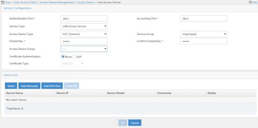
vi Click Add IPv6 Dev in the Device List area to open the page as shown in Figure 50.
vii Enter the access device's IPv6 address 4::2.
viii Click OK.
Figure 50 Manually adding an access device
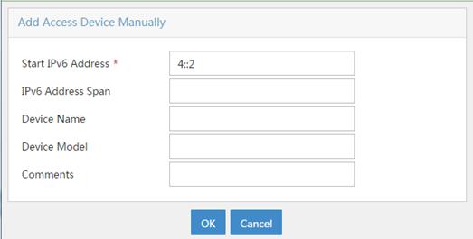
a. Add an access policy:
ix Select User Access Policy > Access Policy from the navigation tree to open the access policy page.
x Click Add to open the page as shown in Figure 51.
xi Enter the access policy name AccessPolicy.
xii Use the default settings for other parameters.
Figure 51 Adding an access policy
a. Add an access service:
xiii Select User Access Policy > Access Service from the navigation tree to open the access service page.
xiv Click Add to open the page as shown in Figure 52.
xv Enter the service name IPoE_Server.
xvi Select AccessPolicy from the default access policy list.
xvii Use the default settings for other parameters.
Figure 52 Adding an access service
a. Add a user:
xviii Select User Management > Add User from the navigation tree to open the adding user page, as shown in Figure 53.
xix Enter the username IPoE_Web001 and the user ID 001.
xx Click OK.
a. Add an access user:
xxi Select Access User > All Access Users from the navigation tree to open the access user page.
xxii Click Add to open the page as shown in Figure 54.
xxiii Select IPoE_Web001 for the username.
xxiv Enter the account name user1.
xxv Enter the password pass1.
xxvi Select the access service IPoE_Server.
Figure 54 Adding an access user
6. Configure the portal server:
|
|
NOTE: The following section uses an IMC server as an example to describe how to configure the portal server. The configuration procedure might vary by IMC version. For the exact configuration procedure, see the guide for the specific IMC version. The configuration procedure in this section is only for your reference. |
a. Configure the portal homepage:
xxvii Select User Access Policy > Portal Service > Server from the navigation tree to open the portal server configuration page, as shown in Figure 55.
xxviii Click OK.
Figure 55 Portal server configuration page
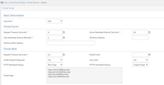
a. Configure portal authentication source IP address range:
xxix Select User Access Policy > Portal Service > IP Group from the navigation tree to open the portal IP address group configuration page.
xxx Click Add to open the page as shown in Figure 56.
xxxi Enter the IP group name IPoE_Web_User-2.
xxxii Select Yes from the IPv6 list.
xxxiii Enter the start IP address (192::1) and end IP address (192::FFFF) of the IP group. Make sure the host IPv6 address is in the IP group.
xxxiv Click OK.
Figure 56 Adding an IP address group (IPv6)
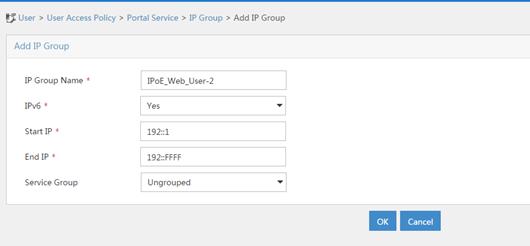
a. Add a portal device:
xxxv Select User Access Policy > Portal Service > Device from the navigation tree to open the portal device configuration page.
xxxvi Click Add to open the page as shown in Figure 57.
xxxvii Enter the device name NAS-2.
xxxviii Select Portal 3.0 from the Version list.
xxxix Enter the IP address of the portal packets' outgoing interface GigabitEthernet 3/1/1 (4::2).
xl Enter the key 123456.
xli Select Directly Connect for access method.
xlii Click OK.
Figure 57 Adding a portal device (IPv6)
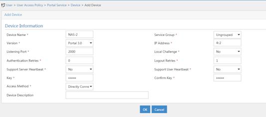
a. Associate the portal device with the IP address group:
xliii Click the icon in the Port Group Information Management column of device NAS to open the port group configuration page, as shown in Figure 58.
xliv Click Add to open the page as shown in Figure 59.
xlv Enter the port group name group-2.
xlvi Select the configured IP address group IPoE_Web_User-2. Make sure the IPv6 address used by the user to access the network is within this IPv6 address group.
xlvii Click OK.
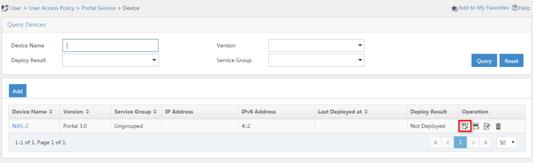
Figure 59 Port group configuration
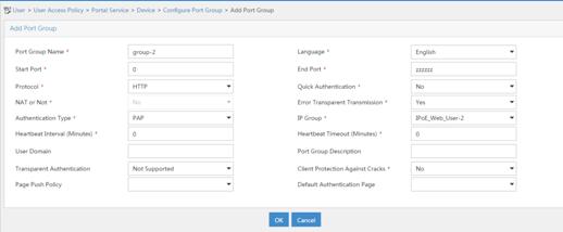
Verifying the configuration
# Display IPoE session information to verify that the host has passed preauthentication and obtained IPv6 address 192::2.
[Device] display ip subscriber session verbose
Basic:
Description : -
Username : 001b21a80949
Domain : dm1
VPN instance : N/A
IPv6 address : 192::2
User address type : N/A
MAC address : 001b-21a8-0949
Service-VLAN/Customer-VLAN : -/-
Access interface : GE3/1/2
User ID : 0x30000004
VPI/VCI(for ATM) : -/-
VSI Index : -
VSI link ID : -
VXLAN ID : -
DNS servers : N/A
IPv6 DNS servers : 8::8
DHCPv6 lease : 2592000 sec
DHCPv6 remain lease : 2591981 sec
Access time : May 27 00:48:51 2018
Online time(hh:mm:ss) : 00:00:19
Service node : Slot 3 CPU 0
Authentication type : Web pre-auth
IPv6 access type : DHCP
IPv6 detect state : Detecting
State : Online
AAA:
ITA policy name : N/A
IP pool : N/A
IPv6 pool : pool1
Primary DNS server : N/A
Secondary DNS server : N/A
Primary IPv6 DNS server : N/A
Secondary IPv6 DNS server : N/A
Session idle cut : N/A
Session duration : N/A, remaining: N/A
Traffic quota : N/A
Traffic remained : N/A
Acct start-fail action : Online
Acct update-fail action : Online
Acct quota-out action : Offline
Dual-stack accounting mode : Merge
Max IPv4 multicast addresses: 4
IPv4 multicast address list : N/A
Max IPv6 multicast addresses: 4
IPv6 multicast address list : N/A
Accounting start time : May 27 00:48:51 2018
Redirect URL : http://www.h3c.web.com
Subscriber ID : -
QoS:
User profile : N/A
Session group profile : N/A
User group ACL : web (active)
Inbound CAR : N/A
Outbound CAR : N/A
Inbound user priority : N/A
Outbound user priority : N/A
Flow statistic:
Uplink packets/bytes : 0/0
Downlink packets/bytes : 0/0
IPv6 uplink packets/bytes : 0/0
IPv6 downlink packets/bytes : 0/0
As shown in Figure 60, the Web login page opens after preauthentication. Enter the username and password on the page.

# Display IPoE session information to verify that the host has passed Web authentication and come online.
[Device] display ip subscriber session verbose
Basic:
Description : -
Username : user1@dm2
Domain : dm2
VPN instance : N/A
IPv6 address : 192::2
User address type : N/A
MAC address : 001b-21a8-0949
Service-VLAN/Customer-VLAN : -/-
Access interface : GE3/1/2
User ID : 0x30000004
VPI/VCI(for ATM) : -/-
VSI Index : -
VSI link ID : -
VXLAN ID : -
DNS servers : N/A
IPv6 DNS servers : 8::8
DHCPv6 lease : 2592000 sec
DHCPv6 remain lease : 2591954 sec
Access time : May 27 00:48:51 2018
Online time(hh:mm:ss) : 00:00:04
Service node : Slot 3 CPU 0
Authentication type : Web
IPv6 access type : DHCP
IPv6 detect state : Detecting
State : Online
AAA:
ITA policy name : N/A
IP pool : N/A
IPv6 pool : pool1
Primary DNS server : N/A
Secondary DNS server : N/A
Primary IPv6 DNS server : N/A
Secondary IPv6 DNS server : N/A
Session idle cut : N/A
Session duration : 86400 sec, remaining: 86395 sec
Traffic quota : N/A
Traffic remained : N/A
Acct start-fail action : Online
Acct update-fail action : Online
Acct quota-out action : Offline
Dual-stack accounting mode : Merge
Max IPv4 multicast addresses: 4
IPv4 multicast address list : N/A
Max IPv6 multicast addresses: 4
IPv6 multicast address list : N/A
Accounting start time : May 27 00:49:32 2018
Subscriber ID : -
QoS:
User profile : car (active)
Session group profile : N/A
User group ACL : N/A
Inbound CAR : N/A
Outbound CAR : N/A
Inbound user priority : N/A
Outbound user priority : N/A
Flow statistic:
Uplink packets/bytes : 14/6204
Downlink packets/bytes : 8/7666
IPv6 uplink packets/bytes : 0/0
IPv6 downlink packets/bytes : 0/0
Example: Configuring IPoE common Web authentication for IPoE ND RS users
Network configuration
As shown in Figure 61, the host accesses the BRAS as an IPv6 ND RS user though a Layer 2 device. The BRAS can send IPv6 ND RA packets. A server installed with H3C IMC acts as the RADIUS server, the portal authentication server, and the portal Web server.
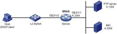
Procedure
1. Configure IP addresses and routes.
As shown in Figure 61, configure IP addresses for interfaces and make sure the BRAS and servers can reach each other at Layer 3. (Details not shown.)
2. Configure the BRAS:
a. Disable RA message suppression on GigabitEthernet 3/1/2.
<Device> system-view
[Device] interface gigabitethernet 3/1/2
[Device–GigabitEthernet3/1/2] undo ipv6 nd ra halt
b. Automatically generate a link-local address for GigabitEthernet 3/1/2.
[Device–GigabitEthernet3/1/2] ipv6 address auto link-local
[Device–GigabitEthernet3/1/2] quit
c. Configure the DHCP server:
# Create prefix pool 1 that contains the prefix 10::/32 and specify the length of prefixes to be assigned as 64. Prefix pool 1 can assign 4294967296 prefixes in the range of 10::/64 to 10:0:FFFF:FFFF::/64.
[Device] ipv6 dhcp prefix-pool 1 prefix 10::/32 assign-len 64
# Create an IPv6 address pool named pool1, and reference prefix pool 1.
[Device] ipv6 pool pool1
[Device-ipv6-pool-pool1] prefix-pool 1
[Device-ipv6-pool-pool1] quit
# Enable the DHCPv6 server on GigabitEthernet 3/1/2.
[Device] interface gigabitethernet 3/1/2
[Device-GigabitEthernet3/1/2] ipv6 dhcp select server
[Device-GigabitEthernet3/1/2] quit
d. Configure the portal servers:
# Configure the IPv6 address of the IPv6 portal authentication server newpt2 as 4::5 and the plaintext key 123456.
[Device] portal server newpt2
[Device-portal-server-newpt2] ipv6 4::5 key simple 123456
[Device-portal-server-newpt2] quit
e. Create a local user group named web.
[Device] user-group web
New user group added.
[Device-ugroup-web] quit
f. Configure ACLs for preauthentication:
# Create an IPv6 advanced ACL named web_permit. Configure a rule to permit all packets destined for the portal server from users in user group web.
[Device] acl ipv6 advanced name web_permit
[Device-acl-ipv6-adv-web_permit] rule 0 permit ipv6 destination 4::5 128 user-group web
[Device-acl-ipv6-adv-web_permit] quit
# Create an IPv6 advanced ACL named neiwang. Configure a rule to permit all packets destined for the internal network server from users in user group web.
[Device] acl ipv6 advanced name neiwang
[Device-acl-ipv6-adv-neiwang] rule 0 permit ipv6 destination 4::1 128 user-group web
[Device-acl-ipv6-adv-neiwang] quit
# Create an IPv6 advanced ACL named web_http. Configure a rule to permit TCP packets with the destination port 80 (HTTP packets) from users in user group web.
[Device] acl ipv6 advanced name web_http
[Device-acl-ipv6-adv-web_http] rule 0 permit tcp destination-port eq www user-group web
[Device-acl-ipv6-adv-web_http] quit
# Create an IPv6 advanced ACL named web_https, and configure a rule to permit TCP packets with the destination port 443 (HTTPS packets) from users in user group web.
[Device] acl ipv6 advanced name web_https
[Device-acl-ipv6-adv-web_https] rule 0 permit tcp destination-port eq 443 user-group web
[Device-acl-ipv6-adv-web_https] quit
# Create an IPv6 advanced ACL named ip, and configure a rule to permit IP packets from users in user group web.
[Device] acl ipv6 advanced name ip
[Device-acl-ipv6-adv-ip] rule 0 permit ipv6 user-group web
[Device-acl-ipv6-adv-ip] quit
# Create an IPv6 advanced ACL named neiwang_out, and configure a rule to permit IP packets from the internal network server in user group web.
[Device] acl ipv6 advanced name neiwang_out
[Device-acl-ipv6-adv-neiwang_out] rule 0 permit ipv6 source 4::1 128 user-group web
[Device-acl-ipv6-adv-neiwang_out] quit
# Create an IPv6 advanced ACL named web_out, and configure a rule to permit IP packets from the portal server in user group web.
[Device] acl ipv6 advanced name web_out
[Device-acl-ipv6-adv-web_out] rule 0 permit ipv6 source 4::5 128 user-group web
[Device-acl-ipv6-adv-web_out] quit
g. Configure QoS traffic classes for preauthentication users:
# Create the traffic class web_permit and specify ACL web_permit as the match criterion.
[Device] traffic classifier web_permit operator or
[Device-classifier-web_permit] if-match acl ipv6 name web_permit
[Device-classifier-web_permit] quit
# Create the traffic class web_http and specify ACL web_http as the match criterion.
[Device] traffic classifier web_http operator or
[Device-classifier-web_http] if-match acl ipv6 name web_http
[Device-classifier-web_http] quit
# Create the traffic class web_https and specify ACL web_https as the match criterion.
[Device] traffic classifier web_https operator or
[Device-classifier-web_https] if-match acl ipv6 name web_https
[Device-classifier-web_https] quit
# Create the traffic class web_deny and specify ACL ip as the match criterion.
[Device] traffic classifier web_deny operator or
[Device-classifier-web_deny] if-match acl ipv6 name ip
[Device-classifier-web_deny] quit
# Create the traffic class neiwang_out and specify ACL neiwang_out as the match criterion.
[Device] traffic classifier neiwang_out operator or
[Device-classifier-neiwang_out] if-match acl ipv6 name neiwang_out
[Device-classifier-neiwang_out] quit
# Create the traffic class web_out and specify ACL web_out as the match criterion.
[Device] traffic classifier web_out operator or
[Device-classifier-web_out] if-match acl ipv6 name web_out
[Device-classifier-web_out] quit
h. Configure QoS traffic behaviors:
# Configure the traffic behavior web_permit to permit traffic to pass through without rate limiting or accounting.
[Device] traffic behavior web_permit
[Device-behavior-web_permit] filter permit
[Device-behavior-web_permit] free account
[Device-behavior-web_permit] quit
# Configure the traffic behavior neiwang to permit traffic to pass through.
[Device] traffic behavior neiwang
[Device-behavior-neiwang] filter permit
[Device-behavior-neiwang] quit
# Configure the traffic behavior web_http to redirect HTTP packets to the CPU.
[Device] traffic behavior web_http
[Device-behavior-web_http] redirect http-to-cpu
[Device-behavior-web_http] quit
# Configure the traffic behavior web_https to redirect HTTPS packets to the CPU.
[Device] traffic behavior web_https
[Device-behavior-web_https] redirect https-to-cpu
[Device-behavior-web_https] quit
# Configure the traffic behavior web_deny to deny traffic.
[Device] traffic behavior web_deny
[Device-behavior-web_deny] filter deny
[Device-behavior-web_deny] free account
[Device-behavior-web_deny] quit
# Configure the traffic behavior neiwang_out to permit traffic to pass through.
[Device] traffic behavior neiwang_out
[Device-behavior-neiwang_out] filter permit
[Device-behavior-neiwang_out] quit
# Configure the traffic behavior web_out to permit traffic without rate limiting or traffic accounting.
[Device] traffic behavior web_out
[Device-behavior-web_out] filter permit
[Device-behavior-web_out] free account
[Device-behavior-web_out] quit
i. Configure the QoS policies:
# Create a QoS policy named web.
[Device] qos policy web
# Associate the traffic class web_permit with the traffic behavior web_permit.
[Device-qospolicy-web] classifier web_permit behavior web_permit
# Associate the traffic class neiwang with the traffic behavior neiwang.
[Device-qospolicy-web] classifier neiwang behavior neiwang
# Associate the traffic class web_http with the traffic behavior web_http.
[Device-qospolicy-web] classifier web_http behavior web_http
# Associate the traffic class web_https with the traffic behavior web_https.
[Device-qospolicy-web] classifier web_https behavior web_https
# Associate the traffic class web_deny with the traffic behavior web_deny.
[Device-qospolicy-web] classifier web_deny behavior web_deny
[Device-qospolicy-web] quit
# Configure a QoS policy named out.
[Device] qos policy out
# Associate the traffic class web_out with the traffic behavior web_out. Associate the traffic class neiwang_out with the traffic behavior neiwang_out. Associate the traffic class web_deny with the traffic behavior web_deny.
[Device-qospolicy-out] classifier web_out behavior web_out
[Device-qospolicy-out] classifier neiwang_out behavior neiwang_out
[Device-qospolicy-out] classifier web_deny behavior web_deny
[Device-qospolicy-out] quit
j. Apply the QoS policies:
# Apply the QoS Policy web to the inbound traffic globally.
[Device] qos apply policy web global inbound
# Apply the QoS Policy out to the outbound traffic globally.
[Device] qos apply policy out global outbound
k. Configure a RADIUS scheme:
# Create a RADIUS scheme named rs1 and enter its view.
[Device] radius scheme rs1
# Configure primary servers and keys for authentication and accounting.
[Device-radius-rs1] primary authentication ipv6 4::5
[Device-radius-rs1] primary accounting ipv6 4::5
[Device-radius-rs1] key authentication simple radius
[Device-radius-rs1] key accounting simple radius
# Exclude the ISP name from the username sent to the RADIUS server.
[Device-radius-rs1] user-name-format without-domain
[Device-radius-rs1] quit
l. Configure the preauthentication ISP domain and Web authentication ISP domain:
# Configure the ISP domain dm1 for IPoE user preauthentication.
[Device] domain name dm1
[Device-isp-dm1] authentication ipoe none
[Device-isp-dm1] authorization ipoe none
[Device-isp-dm1] accounting ipoe none
# Configure the authorized user group, ND prefix pool, and IPv6 DNS address pool in preauthentication ISP domain dm1.
[Device-isp-dm1] authorization-attribute user-group web
[Device-isp-dm1] authorization-attribute ipv6-nd-prefix-pool pool1
[Device-isp-dm1] authorization-attribute primary-dns ipv6 2:2::3
# Configure the Web authentication page URL in ISP domain dm1.
[Device-isp-dm1] web-server url http://[4::5]:8080/portal
[Device-isp-dm1] quit
# Configure the ISP domain dm2 for IPoE user Web authentication.
[Device] domain name dm2
[Device-isp-dm2] authentication ipoe radius-scheme rs1
[Device-isp-dm2] authorization ipoe radius-scheme rs1
[Device-isp-dm2] accounting ipoe radius-scheme rs1
[Device-isp-dm2] quit
m. Configure IPoE:
# Enable IPoE and configure Layer 2 access mode on GigabitEthernet 3/1/2.
[Device] interface gigabitethernet 3/1/2
[Device–GigabitEthernet3/1/2] ip subscriber l2-connected enable
# Configure Web authentication for IPoE users on GigabitEthernet 3/1/2.
[Device–GigabitEthernet3/1/2] ip subscriber authentication-method web
The operation may cut all users on this interface. Continue?[Y/N]:y
# Enable IPv6 ND RS packet initiation.
[Device–GigabitEthernet3/1/2] ip subscriber initiator ndrs enable
# Enable IPv6 ND RS packet initiation on GigabitEthernet 3/1/2.
[Device–GigabitEthernet3/1/2] ip subscriber initiator ndrs enable
# Configure the ISP domain dm1 for preauthentication and the ISP domain dm2 for Web authentication on GigabitEthernet 3/1/2.
[Device–GigabitEthernet3/1/2] ip subscriber pre-auth domain dm1
[Device–GigabitEthernet3/1/2] ip subscriber web-auth domain dm2
[Device–GigabitEthernet3/1/2] quit
3. Configure the RADIUS server and portal server.
For more information, see related configuration in "Example: Configuring IPoE common Web authentication for dual-stack users."
Verifying the configuration
# Display IPoE session information to verify that the host has passed preauthentication and obtained IPv6 prefix 10::.
[Device] display ip subscriber session verbose
Basic:
Description : -
Username : 001b21a80949
Domain : dm1
VPN instance : N/A
IPv6 ND Prefix : 10::/64
User address type : N/A
MAC address : 001b-21a8-0949
Service-VLAN/Customer-VLAN : -/-
Access interface : GE3/1/2
User ID : 0x30000004
VPI/VCI(for ATM) : -/-
VSI Index : -
VSI link ID : -
VXLAN ID : -
DNS servers : N/A
IPv6 DNS servers : 2:2::3
DHCPv6 lease : N/A
DHCPv6 remain lease : N/A
Access time : Jan 30 16:09:55 2019
Online time(hh:mm:ss) : 00:00:19
Service node : Slot 3 CPU 0
Authentication type : Web pre-auth
IPv6 access type : NDRS
IPv6 detect state : Detecting
State : Online
AAA:
ITA policy name : N/A
IP pool : N/A
IPv6 pool : N/A
IPv6 nd prefix pool : pool1
Primary DNS server : N/A
Secondary DNS server : N/A
Primary IPv6 DNS server : 2:2::3
Secondary IPv6 DNS server : N/A
Session idle cut : N/A
Session duration : N/A, remaining: N/A
Traffic quota : N/A
Traffic remained : N/A
Acct start-fail action : Online
Acct update-fail action : Online
Acct quota-out action : Offline
Dual-stack accounting mode : Merge
Max IPv4 multicast addresses: 4
IPv4 multicast address list : N/A
Max IPv6 multicast addresses: 4
IPv6 multicast address list : N/A
Accounting start time : Jan 30 16:17:21 2019
Redirect URL : http://[4::5]:8080/portal
Subscriber ID : -
QoS:
User profile : N/A
Session group profile : N/A
User group ACL : web (active)
Inbound CAR : N/A
Outbound CAR : N/A
Inbound user priority : N/A
Outbound user priority : N/A
Flow statistic:
Uplink packets/bytes : 0/0
Downlink packets/bytes : 0/0
IPv6 uplink packets/bytes : 0/0
IPv6 downlink packets/bytes : 0/0
As shown in Figure 62, the Web login page opens after preauthentication. Enter the username and password on the page.
# Display IPoE session information to verify that the host has passed Web authentication and come online.
[Device] display ip subscriber session verbose
Basic:
Description : -
Username : user1@dm2
Domain : dm2
VPN instance : N/A
IPv6 ND Prefix : 10::/64
User address type : N/A
MAC address : 001b-21a8-0949
Service-VLAN/Customer-VLAN : -/-
Access interface : GE3/1/2
User ID : 0x30000004
VPI/VCI(for ATM) : -/-
VSI Index : -
VSI link ID : -
VXLAN ID : -
DNS servers : 2:2::3
IPv6 DNS servers : N/A
DHCPv6 lease : N/A
DHCPv6 remain lease : N/A
Access time : Jan 30 16:20:35 2019
Online time(hh:mm:ss) : 00:00:04
Service node : Slot 3 CPU 0
Authentication type : Web
IPv6 access type : NDRS
IPv6 detect state : Detecting
State : Online
AAA:
ITA policy name : N/A
IP pool : N/A
IPv6 pool : N/A
IPv6 nd prefix pool : pool1
Primary DNS server : N/A
Secondary DNS server : N/A
Primary IPv6 DNS server : 2:2::3
Secondary IPv6 DNS server : N/A
Session idle cut : N/A
Session duration : N/A, remaining: N/A
Traffic quota : N/A
Traffic remained : N/A
Acct start-fail action : Online
Acct update-fail action : Online
Acct quota-out action : Offline
Dual-stack accounting mode : Merge
Max IPv4 multicast addresses: 4
IPv4 multicast address list : N/A
Max IPv6 multicast addresses: 4
IPv6 multicast address list : N/A
Accounting start time : Jan 30 16:22:21 2019
Subscriber ID : -
QoS:
User profile : N/A
Session group profile : N/A
User group ACL : N/A
Inbound CAR : N/A
Outbound CAR : N/A
Inbound user priority : N/A
Outbound user priority : N/A
Flow statistic:
Uplink packets/bytes : 0/0
Downlink packets/bytes : 0/0
IPv6 uplink packets/bytes : 0/0
IPv6 downlink packets/bytes : 0/0
Example: Configuring IPoE common Web authentication for dual-stack users
Network configuration
As shown in Figure 63, the host accesses the BRAS as a DHCP client though a Layer 2 device. It obtains configuration information from the DHCP server through the BRAS. The BRAS performs AAA for the host through the RADIUS server. A server installed with H3C IMC acts as the RADIUS server, the portal authentication server, and the portal Web server. The FTP server is an internal network server. Limit the access rate to 5 Mbps for the user after passing Web authentication.
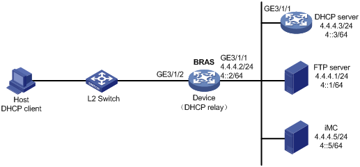
Procedure
1. Configure IP addresses and routes.
As shown in Figure 63, configure IP addresses for interfaces and make sure the BRAS and servers can reach each other at Layer 3. (Details not shown.)
2. Configure the DNS server.
Configure the DNS server properly, so that the server can parse the IPv4 URL or IPv6 URL corresponding to the Web authentication page http://www.h3c.web.com according to the first protocol stack that comes online of the IPoE dual-stack user. (Details not shown.)
3. Configure the DHCP servers:
a. Configure the DHCPv4 address pool:
# Enable DHCP.
<DHCP> system-view
[DHCP] dhcp enable
# Create a DHCPv4 address pool named pool1 and enter its view.
[DHCP] dhcp server ip-pool pool1
# Specify primary subnet 192.168.0.0/24 for dynamic allocation in DHCPv4 address pool pool1.
[DHCP-dhcp-pool-pool1] network 192.168.0.0 24
# Specify gateway address 192.168.0.1 and DNS server address 8.8.8.8 in DHCPv4 address pool pool1.
[DHCP-dhcp-pool-pool1] gateway-list 192.168.0.1
[DHCP-dhcp-pool-pool1] dns-list 8.8.8.8
# Exclude IP address 192.168.0.1 from dynamic allocation in DHCPv4 address pool pool1.
[DHCP-dhcp-pool-pool1] forbidden-ip 192.168.0.1
[DHCP-dhcp-pool-pool1] quit
# Configure a static route to specify the next hop of DHCPv4 replies destined to network segment 192.168.0.0 as the IP address of the interface connected to the DHCPv4 client, 4.4.4.2.
[DHCP] ip route-static 192.168.0.0 24 4.4.4.2
b. Configure the DHCPv6 address pool:
# Create a DHCPv6 address pool named pool2 and enter its view.
[DHCP] ipv6 dhcp pool pool2
# Specify primary subnet 192::0/64 and DNS server address 8::8 for dynamic allocation in DHCPv6 address pool pool2.
[DHCP-dhcp6-pool-pool2] network 192::0/64
[DHCP-dhcp6-pool-pool2] dns-server 8::8
[DHCP-dhcp6-pool-pool2] quit
# Exclude IP address 192::1 from dynamic allocation in DHCPv6 address pool pool2.
[DHCP] ipv6 dhcp server forbidden-address 192::1
# Enable the DHCPv6 server on GigabitEthernet 3/1/1.
[DHCP] interface gigabitethernet 3/1/1
[DHCP-GigabitEthernet3/1/1] ipv6 dhcp select server
[DHCP-GigabitEthernet3/1/1] quit
# Configure a static route to specify the next hop of DHCPv6 replies destined to network segment 192::0 as the IP address of the interface connected to the DHCPv6 client, 4::2.
[DHCP] ipv6 route-static 192::0 64 4::2
4. Configure the BRAS:
a. Configure the DHCP relay agent:
# Enable DHCP.
<Device> system-view
[Device] dhcp enable
# Enable the DHCP relay agent to record client information in relay entries.
[Device] dhcp relay client-information record
# Disable the DHCP relay agent from periodically refreshing dynamic relay entries.
[Device] undo dhcp relay client-information refresh enable
# Create an IP address pool named pool1 for the DHCP relay agent.
[Device] dhcp server ip-pool pool1
# Specify gateway address 192.168.0.1 in DHCP address pool pool1.
[Device-dhcp-pool-pool1] gateway-list 192.168.0.1 export-route
# Specify DHCP server 4.4.4.3 in DHCP address pool pool1.
[Device-dhcp-pool-pool1] remote-server 4.4.4.3
[Device-dhcp-pool-pool1] quit
# Create an IP address pool named pool2 for the DHCP relay agent.
[Device] ipv6 dhcp pool pool2
# Specify gateway address 192::1 in DHCP address pool pool2.
[Device-dhcp6-pool-pool2] gateway-list 192::1
# Specify DHCP server 4::3 in DHCP address pool pool2.
[Device-dhcp6-pool-pool2] remote-server 4::3
[Device-dhcp6-pool-pool2] quit
# Enable DHCP server proxy on the DHCPv4 relay agent on GigabitEthernet 3/1/2.
[Device] interface gigabitethernet 3/1/2
[Device–GigabitEthernet3/1/2] dhcp select relay proxy
# Automatically generate a link-local address for GigabitEthernet 3/1/2.
[Device–GigabitEthernet3/1/2] ipv6 address auto link-local
# Enable the DHCPv6 relay agent on GigabitEthernet 3/1/2.
[Device–GigabitEthernet3/1/2] ipv6 dhcp select relay
# Enable recording client information in DHCPv6 relay entries.
[Device–GigabitEthernet3/1/2] ipv6 dhcp relay client-information record
# Disable RA message suppression on GigabitEthernet 3/1/2.
[Device–GigabitEthernet3/1/2] undo ipv6 nd ra halt
# Set the managed address configuration flag (M) to 1 in RA advertisements to be sent. Then, the host uses a DHCPv6 server to obtain IPv6 addresses.
[Device–GigabitEthernet3/1/2] ipv6 nd autoconfig managed-address-flag
# Set the other stateful configuration flag (O) to 1 in RA advertisements to be sent. Then, the host uses a DHCPv6 server to obtain configuration information other than IPv6 addresses.
[Device–GigabitEthernet3/1/2] ipv6 nd autoconfig other-flag
# Disable GigabitEthernet 3/1/2 from advertising the specified prefix in RA messages, preventing the endpoint from obtaining a temporary IPv6 address. In an IPv6 network, an endpoint might use a temporary IPv6 address for IPoE Web authentication, which will cause authentication failure.
[Device–GigabitEthernet3/1/2] ipv6 nd ra prefix 192::/64 no-advertise
[Device–GigabitEthernet3/1/2] quit
b. Configure the portal servers:
# Configure the IP address of the IPv4 portal authentication server newpt1 as 4.4.4.5 and the plaintext key 123456.
[Device] portal server newpt1
[Device-portal-server-newpt1] ip 4.4.4.5 key simple 123456
[Device-portal-server-newpt1] quit
# Configure the IPv6 address of the IPv6 portal authentication server newpt2 as 4::5 and the plaintext key 123456.
[Device] portal server newpt2
[Device-portal-server-newpt2] ipv6 4::5 key simple 123456
[Device-portal-server-newpt2] quit
c. Specify 11111 as the HTTPS redirect listening port number.
[Device] http-redirect https-port 11111
d. Create a local user group named web.
[Device] user-group web
New user group added.
[Device-ugroup-web] quit
e. Configure ACLs for preauthentication:
# Create an IPv4 and IPv6 advanced ACL named web_permit separately. Configure a rule to permit all packets destined for the portal server from users in user group web.
[Device] acl advanced name web_permit
[Device-acl-ipv4-adv-web_permit] rule 0 permit ip destination 4.4.4.5 0 user-group web
[Device-acl-ipv4-adv-web_permit] quit
[Device] acl ipv6 advanced name web_permit
[Device-acl-ipv6-adv-web_permit] rule 0 permit ipv6 destination 4::5 128 user-group web
[Device-acl-ipv6-adv-web_permit] quit
# Create an IPv4 and IPv6 advanced ACL named neiwang separately. Configure a rule to permit all packets destined for the internal network server from users in user group web.
[Device] acl advanced name neiwang
[Device-acl-ipv4-adv-neiwang] rule 0 permit ip destination 4.4.4.1 0 user-group web
[Device-acl-ipv4-adv-neiwang] quit
[Device] acl ipv6 advanced name neiwang
[Device-acl-ipv6-adv-neiwang] rule 0 permit ipv6 destination 4::1 128 user-group web
[Device-acl-ipv6-adv-neiwang] quit
# Create an IPv4 and IPv6 advanced ACL named web_http separately. Configure a rule to permit TCP packets with the destination port 80 (HTTP packets) from users in user group web.
[Device] acl advanced name web_http
[Device-acl-ipv4-adv-web_http] rule 0 permit tcp destination-port eq www user-group web
[Device-acl-ipv4-adv-web_http] quit
[Device] acl ipv6 advanced name web_http
[Device-acl-ipv6-adv-web_http] rule 0 permit tcp destination-port eq www user-group web
[Device-acl-ipv6-adv-web_http] quit
# Create an IPv4 and IPv6 advanced ACL named web_https separately, and configure a rule to permit TCP packets with the destination port 443 (HTTPS packets) from users in user group web.
[Device] acl advanced name web_https
[Device-acl-ipv4-adv-web_https] rule 0 permit tcp destination-port eq 443 user-group web
[Device-acl-ipv4-adv-web_https] quit
[Device] acl ipv6 advanced name web_https
[Device-acl-ipv6-adv-web_https] rule 0 permit tcp destination-port eq 443 user-group web
[Device-acl-ipv6-adv-web_https] quit
# Create an IPv4 and IPv6 advanced ACL named ip separately, and configure a rule to permit IP packets from users in user group web.
[Device] acl advanced name ip
[Device-acl-ipv4-adv-ip] rule 0 permit ip user-group web
[Device-acl-ipv4-adv-ip] quit
[Device] acl ipv6 advanced name ip
[Device-acl-ipv6-adv-ip] rule 0 permit ipv6 user-group web
[Device-acl-ipv6-adv-ip] quit
# Create an IPv4 and IPv6 advanced ACL named neiwang_out separately, and configure a rule to permit IP packets from the internal network server in user group web.
[Device] acl advanced name neiwang_out
[Device-acl-ipv4-adv-neiwang_out] rule 0 permit ip source 4.4.4.1 0 user-group web
[Device-acl-ipv4-adv-neiwang_out] quit
[Device] acl ipv6 advanced name neiwang_out
[Device-acl-ipv6-adv-neiwang_out] rule 0 permit ipv6 source 4::1 128 user-group web
[Device-acl-ipv6-adv-neiwang_out] quit
# Create an IPv4 and IPv6 advanced ACL named web_out separately, and configure a rule to permit IP packets from the portal server in user group web.
[Device] acl advanced name web_out
[Device-acl-ipv4-adv-web_out] rule 0 permit ip source 4.4.4.5 0 user-group web
[Device-acl-ipv4-adv-web_out] quit
[Device] acl ipv6 advanced name web_out
[Device-acl-ipv6-adv-web_out] rule 0 permit ipv6 source 4::5 128 user-group web
[Device-acl-ipv6-adv-web_out] quit
f. Configure QoS traffic classes for preauthentication users:
# Create the traffic class web_permit and specify ACL web_permit as the match criterion.
[Device] traffic classifier web_permit operator or
[Device-classifier-web_permit] if-match acl name web_permit
[Device-classifier-web_permit] if-match acl ipv6 name web_permit
[Device-classifier-web_permit] quit
# Create the traffic class neiwang and specify ACL neiwang as the match criterion.
[Device] traffic classifier neiwang operator or
[Device-classifier-neiwang] if-match acl name neiwang
[Device-classifier-neiwang] if-match acl ipv6 name neiwang
[Device-classifier-neiwang] quit
# Create the traffic class web_http and specify ACL web_http as the match criterion.
[Device] traffic classifier web_http operator or
[Device-classifier-web_http] if-match acl name web_http
[Device-classifier-web_http] if-match acl ipv6 name web_http
[Device-classifier-web_http] quit
# Create the traffic class web_https and specify ACL web_https as the match criterion.
[Device] traffic classifier web_https operator or
[Device-classifier-web_https] if-match acl name web_https
[Device-classifier-web_https] if-match acl ipv6 name web_https
[Device-classifier-web_https] quit
# Create the traffic class web_deny and specify ACL ip as the match criterion.
[Device] traffic classifier web_deny operator or
[Device-classifier-web_deny] if-match acl name ip
[Device-classifier-web_deny] if-match acl ipv6 name ip
[Device-classifier-web_deny] quit
# Create the traffic class neiwang_out and specify ACL neiwang_out as the match criterion.
[Device] traffic classifier neiwang_out operator or
[Device-classifier-neiwang_out] if-match acl name neiwang_out
[Device-classifier-neiwang_out] if-match acl ipv6 name neiwang_out
[Device-classifier-neiwang_out] quit
# Create the traffic class web_out and specify ACL web_out as the match criterion.
[Device] traffic classifier web_out operator or
[Device-classifier-web_out] if-match acl name web_out
[Device-classifier-web_out] if-match acl ipv6 name web_out
[Device-classifier-web_out] quit
g. Configure QoS traffic behaviors:
# Configure the traffic behavior web_permit to permit traffic to pass through without rate limiting or accounting.
[Device] traffic behavior web_permit
[Device-behavior-web_permit] filter permit
[Device-behavior-web_permit] free account
[Device-behavior-web_permit] quit
# Configure the traffic behavior neiwang to permit traffic to pass through.
[Device] traffic behavior neiwang
[Device-behavior-neiwang] filter permit
[Device-behavior-neiwang] quit
# Configure the traffic behavior web_http to redirect HTTP packets to the CPU.
[Device] traffic behavior web_http
[Device-behavior-web_http] redirect http-to-cpu
[Device-behavior-web_http] quit
# Configure the traffic behavior web_https to redirect HTTPS packets to the CPU.
[Device] traffic behavior web_https
[Device-behavior-web_https] redirect https-to-cpu
[Device-behavior-web_https] quit
# Configure the traffic behavior web_deny to deny traffic.
[Device] traffic behavior web_deny
[Device-behavior-web_deny] filter deny
[Device-behavior-web_deny] free account
[Device-behavior-web_deny] quit
# Configure the traffic behavior neiwang_out to permit traffic to pass through.
[Device] traffic behavior neiwang_out
[Device-behavior-neiwang_out] filter permit
[Device-behavior-neiwang_out] quit
# Configure the traffic behavior web_out to permit traffic without rate limiting or traffic accounting.
[Device] traffic behavior web_out
[Device-behavior-web_out] filter permit
[Device-behavior-web_out] free account
[Device-behavior-web_out] quit
h. Configure the QoS policies:
# Create a QoS policy named web.
[Device] qos policy web
# Associate the traffic class web_permit with the traffic behavior web_permit.
[Device-qospolicy-web] classifier web_permit behavior web_permit
# Associate the traffic class neiwang with the traffic behavior neiwang.
[Device-qospolicy-web] classifier neiwang behavior neiwang
# Associate the traffic class web_http with the traffic behavior web_http.
[Device-qospolicy-web] classifier web_http behavior web_http
# Associate the traffic class web_https with the traffic behavior web_https.
[Device-qospolicy-web] classifier web_https behavior web_https
# Associate the traffic class web_deny with the traffic behavior web_deny.
[Device-qospolicy-web] classifier web_deny behavior web_deny
[Device-qospolicy-web] quit
# Configure a QoS policy named out.
[Device] qos policy out
# Associate the traffic class web_out with the traffic behavior web_out. Associate the traffic class neiwang_out with the traffic behavior neiwang_out. Associate the traffic class web_deny with the traffic behavior web_deny.
[Device-qospolicy-out] classifier web_out behavior web_out
[Device-qospolicy-out] classifier neiwang_out behavior neiwang_out
[Device-qospolicy-out] classifier web_deny behavior web_deny
[Device-qospolicy-out] quit
i. Apply the QoS policies:
# Apply the QoS Policy web to the inbound traffic globally.
[Device] qos apply policy web global inbound
# Apply the QoS Policy out to the outbound traffic globally.
[Device] qos apply policy out global outbound
j. Verify that the applied QoS policies take effect:
# Display the configuration and running status of the QoS policy applied to the inbound traffic globally.
[Device] display qos policy global slot 3 inbound
Direction: Inbound
Policy: web
Classifier: web_permit
Operator: OR
Rule(s) :
If-match acl name web_permit
If-match acl ipv6 name web_permit
Behavior: web_permit
Filter enable: Permit
Free account enable
Classifier: neiwang
Operator: OR
Rule(s) :
If-match acl name neiwang
If-match acl ipv6 name neiwang
Behavior: neiwang
Filter enable: Permit
Classifier: web_http
Operator: OR
Rule(s) :
If-match acl name web_http
If-match acl ipv6 name web_http
Behavior: web_http
Redirecting:
Redirect http to CPU
Classifier: web_https
Operator: OR
Rule(s) :
If-match acl name web_https
If-match acl ipv6 name web_https
Behavior: web_https
Redirecting:
Redirect https to CPU
Classifier: web_deny
Operator: OR
Rule(s) :
If-match acl name ip
If-match acl ipv6 name ip
Behavior: web_deny
Filter enable: Deny
Free account enable
# Display the configuration and running status of the QoS policy applied to the outbound traffic globally.
[Device] display qos policy global slot 3 outbound
Direction: Outbound
Policy: out
Classifier: web_out
Operator: OR
Rule(s) :
If-match acl name web_out
If-match acl ipv6 name web_out
Behavior: web_out
Filter enable: Permit
Free account enable
Classifier: neiwang_out
Operator: OR
Rule(s) :
If-match acl name neiwang_out
If-match acl ipv6 name neiwang_out
Behavior: neiwang_out
Filter enable: Permit
Classifier: web_deny
Operator: OR
Rule(s) :
If-match acl name ip
If-match acl ipv6 name ip
Behavior: web_deny
Filter enable: Deny
Free account enable
k. Configure a RADIUS scheme:
# Create a RADIUS scheme named rs1 and enter its view.
[Device] radius scheme rs1
# Configure primary servers and keys for authentication and accounting.
[Device-radius-rs1] primary authentication 4.4.4.5
[Device-radius-rs1] primary accounting 4.4.4.5
[Device-radius-rs1] key authentication simple radius
[Device-radius-rs1] key accounting simple radius
# Exclude the ISP name from the username sent to the RADIUS server.
[Device-radius-rs1] user-name-format without-domain
[Device-radius-rs1] quit
# Set the IP address of the RADIUS DAE client to 4.4.4.5, and set the shared key to radius for the RADIUS DAE client to exchange DAE packets.
[Device] radius dynamic-author server
[Device-radius-da-server] client ip 4.4.4.5 key simple radius
[Device-radius-da-server] quit
l. Configure the user profile:
# Create a user profile named car. Configure the user profile to perform traffic policing for incoming traffic of online users, with the CIR as 5210 kbps and CBS as 325625 bytes.
[Device] user-profile car
[Device-user-profile-car] qos car inbound any cir 5210 cbs 325625
[Device-user-profile-car] quit
m. Configure the preauthentication ISP domain and Web authentication ISP domain:
# Configure the ISP domain dm1 for IPoE user preauthentication.
[Device] domain name dm1
[Device-isp-dm1] authentication ipoe none
[Device-isp-dm1] authorization ipoe none
[Device-isp-dm1] accounting ipoe none
# Configure the authorized user group and IP address pools in preauthentication ISP domain dm1.
[Device-isp-dm1] authorization-attribute user-group web
[Device-isp-dm1] authorization-attribute ip-pool pool1
[Device-isp-dm1] authorization-attribute ipv6-pool pool2
# Configure the Web authentication page URL in ISP domain dm1.
[Device-isp-dm1] web-server url http://www.h3c.web.com
[Device-isp-dm1] quit
# Configure the ISP domain dm2 for IPoE user Web authentication.
[Device] domain name dm2
[Device-isp-dm2] authentication ipoe radius-scheme rs1
[Device-isp-dm2] authorization ipoe radius-scheme rs1
[Device-isp-dm2] accounting ipoe radius-scheme rs1
[Device-isp-dm2] authorization-attribute user-profile car
[Device-isp-dm2] quit
n. Configure IPoE:
# Enable IPoE and configure Layer 2 access mode on GigabitEthernet 3/1/2.
[Device] interface gigabitethernet 3/1/2
[Device–GigabitEthernet3/1/2] ip subscriber l2-connected enable
# Configure Web authentication for IPoE users on GigabitEthernet 3/1/2.
[Device–GigabitEthernet3/1/2] ip subscriber authentication-method web
The operation may cut all users on this interface. Continue?[Y/N]:y
# Configure the ISP domain dm1 for preauthentication and the ISP domain dm2 for Web authentication on GigabitEthernet 3/1/2.
[Device–GigabitEthernet3/1/2] ip subscriber pre-auth domain dm1
[Device–GigabitEthernet3/1/2] ip subscriber web-auth domain dm2
[Device–GigabitEthernet3/1/2] quit
5. Configure the RADIUS server:
|
|
NOTE: The following section uses an IMC server as an example to describe how to configure the RADIUS server. The configuration procedure might vary by IMC version. For the exact configuration procedure, see the guide for the specific IMC version. The configuration procedure in this section is only for your reference. |
a. Configure the access device:
i Log in to the IMC platform and click the User tab.
ii Select User Access Policy > Access Device Management > Access Device from the navigation tree to open the access device configuration page.
iii Click Add to open the page as shown in Figure 64.
iv Enter the shared key radius.
v Use the default settings for other parameters.
Figure 64 Adding an access device

vi Click Add Manually in the Device List area to open the page as shown in Figure 65.
vii Enter the access device's IP address 4.4.4.2.
viii Click OK.
Figure 65 Manually adding an access device

a. Add an access policy:
ix Select User Access Policy > Access Policy from the navigation tree to open the access policy page.
x Click Add to open the page as shown in Figure 66.
xi Enter the access policy name AccessPolicy.
xii Use the default settings for other parameters.
Figure 66 Adding an access policy
a. Add an access service:
i Select User Access Policy > Access Service from the navigation tree to open the access service page.
ii Click Add to open the page as shown in Figure 67.
iii Enter the service name IPoE_Server.
iv Select AccessPolicy from the default access policy list.
v Use the default settings for other parameters.
Figure 67 Adding an access service
a. Add a user:
i Select User Management > Add User from the navigation tree to open the adding user page, as shown in Figure 68.
ii Enter the username IPoE_Web001 and the user ID 001.
iii Click OK.
a. Add an access user:
i Select Access User > All Access Users from the navigation tree to open the access user page.
ii Click Add to open the page as shown in Figure 69.
iii Select IPoE_Web001 for the username.
iv Enter the account name user1.
v Enter the password pass1.
vi Select the access service IPoE_Server.
Figure 69 Adding an access user
6. Configure the portal server:
|
|
NOTE: The following section uses an IMC server as an example to describe how to configure the portal server. The configuration procedure might vary by IMC version. For the exact configuration procedure, see the guide for the specific IMC version. The configuration procedure in this section is only for your reference. |
a. Configure the portal homepage:
i Select User Access Policy > Portal Service > Server from the navigation tree to open the portal server configuration page, as shown in Figure 70.
ii Click OK.
Figure 70 Portal server configuration page
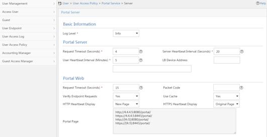
a. Configure portal authentication source IP address range:
i Select User Access Policy > Portal Service > IP Group from the navigation tree to open the portal IP address group configuration page.
ii Click Add to open the page as shown in Figure 71.
iii Enter the IP group name IPoE_Web_User.
iv Enter the start IP address (192.168.0.1) and end IP address (192.168.0.255) of the IP group. Make sure the host IP address is in the IP group.
v Click OK.
Figure 71 Adding an IP address group (IPv4)
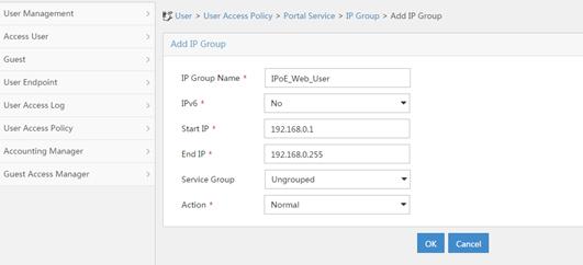
vi Select User Access Policy > Portal Service > IP Group from the navigation tree to open the portal IP address group configuration page.
vii Click Add to open the page as shown in Figure 72.
viii Enter the IP group name IPoE_Web_User-2.
ix Select Yes from the IPv6 list.
x Enter the start IP address (192::1) and end IP address (192::FFFF) of the IP group. Make sure the host IPv6 address is in the IP group.
xi Click OK.
Figure 72 Adding an IP address group (IPv6)
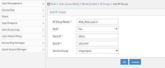
a. Add a portal device:
i Select User Access Policy > Portal Service > Device from the navigation tree to open the portal device configuration page.
ii Click Add to open the page as shown in Figure 73.
iii Enter the device name NAS.
iv Enter the IP address of the portal packets' outgoing interface GigabitEthernet 3/1/1 (4.4.4.2).
v Enter the key 123456.
vi Select Directly Connect for access method.
vii Click OK.
Figure 73 Adding a portal device (IPv4)
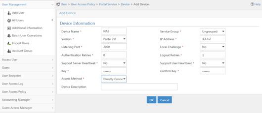
viii Select User Access Policy > Portal Service > Device from the navigation tree to open the portal device configuration page.
ix Click Add to open the page as shown in Figure 74.
x Enter the device name NAS-2.
xi Select Portal 3.0 from the Version list.
xii Enter the IP address of the portal packets' outgoing interface GigabitEthernet 3/1/1 (4::2).
xiii Enter the key 123456.
xiv Select Directly Connect for access method.
xv Click OK.
Figure 74 Adding a portal device (IPv6)
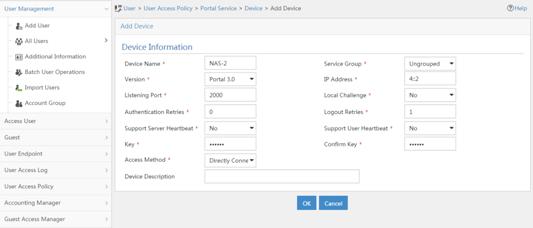
a. Associate the portal device with the IP address group:
i Select User Access Policy > Portal Service > Device from the navigation tree to open the portal device configuration page.
ii Click the icon in the Port Group Information Management column of device NAS to open the port group configuration page, as shown in Figure 75.
iii Click Add to open the page as shown in Figure 76.
iv Enter the port group name group.
v Select the configured IP address group IPoE_Web_User. Make sure the IP address used by the user to access the network is within this IP address group.
vi Click OK.
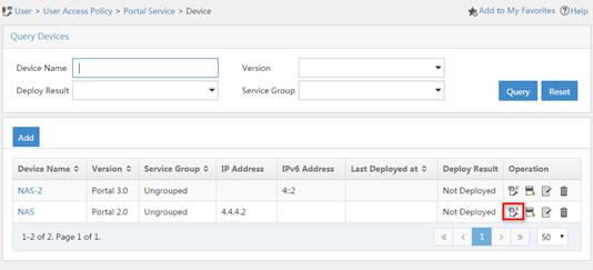
Figure 76 Port group configuration (IPv4)
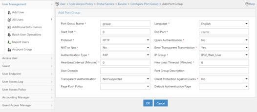
vii Select User Access Policy > Portal Service > Device from the navigation tree to open the portal device configuration page.
viii Click the icon in the Port Group Information Management column of device NAS-2 to open the port group configuration page, as shown in Figure 75.
ix Click Add to open the page as shown in Figure 77.
x Enter the port group name group-2.
xi Select the configured IP address group IPoE_Web_User-2. Make sure the IPv6 address used by the user to access the network is within this IPv6 address group.
xii Click OK.
Figure 77 Port group configuration (IPv6)
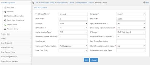
a. From the navigation tree, select User Access Manager > Service Parameters > Validate System Configuration to validate the settings.
Verifying the configuration
# Display IPoE session information to verify that the host has passed preauthentication and obtained IPv4 address 192.168.0.2 and IPv6 address 192::2.
[Device] display ip subscriber session verbose
Basic:
Description : -
Username : 001b21a80949
Domain : dm1
VPN instance : N/A
IP address : 192.168.0.2
IPv6 address : 192::2
User address type : N/A
MAC address : 001b-21a8-0949
Service-VLAN/Customer-VLAN : -/-
Access interface : GE3/1/2
User ID : 0x30000004
VPI/VCI(for ATM) : -/-
VSI Index : -
VSI link ID : -
VXLAN ID : -
DNS servers : 8.8.8.8
IPv6 DNS servers : 8::8
DHCP lease : 86400 sec
DHCP remain lease : 86383 sec
DHCPv6 lease : 2592000 sec
DHCPv6 remain lease : 2591981 sec
Access time : May 27 00:48:51 2018
Online time(hh:mm:ss) : 00:00:19
Service node : Slot 3 CPU 0
Authentication type : Web pre-auth
IPv4 access type : DHCP
IPv6 access type : DHCP
IPv4 detect state : Detecting
IPv6 detect state : Detecting
State : Online
AAA:
ITA policy name : N/A
IP pool : pool1
IPv6 pool : pool2
Primary DNS server : N/A
Secondary DNS server : N/A
Primary IPv6 DNS server : N/A
Secondary IPv6 DNS server : N/A
Session idle cut : N/A
Session duration : N/A, remaining: N/A
Traffic quota : N/A
Traffic remained : N/A
Acct start-fail action : Online
Acct update-fail action : Online
Acct quota-out action : Offline
Dual-stack accounting mode : Merge
Max IPv4 multicast addresses: 4
IPv4 multicast address list : N/A
Max IPv6 multicast addresses: 4
IPv6 multicast address list : N/A
Accounting start time : May 27 00:48:51 2018
Redirect URL : http://www.h3c.web.com
Subscriber ID : -
QoS:
User profile : N/A
Session group profile : N/A
User group ACL : web (active)
Inbound CAR : N/A
Outbound CAR : N/A
Inbound user priority : N/A
Outbound user priority : N/A
Flow statistic:
Uplink packets/bytes : 0/0
Downlink packets/bytes : 0/0
IPv6 uplink packets/bytes : 0/0
IPv6 downlink packets/bytes : 0/0
As shown in Figure 78, the Web login page opens after preauthentication. Enter the username and password on the page.

# Display IPoE session information to verify that the host has passed Web authentication and come online.
[Device] display ip subscriber session verbose
Basic:
Description : -
Username : user1@dm2
Domain : dm2
VPN instance : N/A
IP address : 192.168.0.2
IPv6 address : 192::2
User address type : N/A
MAC address : 001b-21a8-0949
Service-VLAN/Customer-VLAN : -/-
Access interface : GE3/1/2
User ID : 0x30000004
VPI/VCI(for ATM) : -/-
VSI Index : -
VSI link ID : -
VXLAN ID : -
DNS servers : 8.8.8.8
IPv6 DNS servers : 8::8
DHCP lease : 86400 sec
DHCP remain lease : 86356 sec
DHCPv6 lease : 2592000 sec
DHCPv6 remain lease : 2591954 sec
Access time : May 27 00:49:20 2018
Online time(hh:mm:ss) : 00:00:04
Service node : Slot 3 CPU 0
Authentication type : Web
IPv4 access type : DHCP
IPv6 access type : DHCP
IPv4 detect state : Detecting
IPv6 detect state : Detecting
State : Online
AAA:
ITA policy name : N/A
IP pool : pool1
IPv6 pool : pool2
Primary DNS server : N/A
Secondary DNS server : N/A
Primary IPv6 DNS server : N/A
Secondary IPv6 DNS server : N/A
Session idle cut : N/A
Session duration : 86400 sec, remaining: 86395 sec
Traffic quota : N/A
Traffic remained : N/A
Acct start-fail action : Online
Acct update-fail action : Online
Acct quota-out action : Offline
Dual-stack accounting mode : Merge
Max IPv4 multicast addresses: 4
IPv4 multicast address list : N/A
Max IPv6 multicast addresses: 4
IPv6 multicast address list : N/A
Accounting start time : May 27 00:49:20 2018
Subscriber ID : -
QoS:
User profile : car (active)
Session group profile : N/A
User group ACL : N/A
Inbound CAR : N/A
Outbound CAR : N/A
Inbound user priority : N/A
Outbound user priority : N/A
Flow statistic:
Uplink packets/bytes : 0/0
Downlink packets/bytes : 0/0
IPv6 uplink packets/bytes : 0/0
IPv6 downlink packets/bytes : 0/0
Example: Configuring IPoE Layer 2 transparent MAC-trigger authentication
Network configuration
As shown in Figure 79, the host accesses the BRAS as a DHCP client though a Layer 2 device. It obtains configuration information from the DHCP server through the BRAS. A server installed with H3C IMC acts as the RADIUS server, the portal authentication server, the portal Web server, and the MAC binding server. The FTP server is an internal network server.
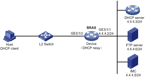
Procedure
1. Configure the DHCP server:
# Enable DHCP.
<DHCP-server> system-view
[DHCP-server] dhcp enable
# Create an IP address pool named pool1 and enter its view.
[DHCP-server] dhcp server ip-pool pool1
# Specify primary subnet 192.168.0.0/24 for dynamic allocation in DHCP address pool pool1.
[DHCP-server-dhcp-pool-pool1] network 192.168.0.0 24
# Specify gateway address 192.168.0.1 in DHCP address pool pool1.
[DHCP-server-dhcp-pool-pool1] gateway-list 192.168.0.1
# Specify DNS server address 8.8.8.8 in DHCP address pool pool1.
[DHCP-server-dhcp-pool-pool1] dns-list 8.8.8.8
# Exclude IP address 192.168.0.1 from dynamic allocation in DHCP address pool pool1.
[DHCP-server-dhcp-pool-pool1] forbidden-ip 192.168.0.1
[DHCP-server-dhcp-pool-pool1] quit
# Configure a static route to specify the next hop of DHCP replies destined to network segment 192.168.0.0 as the IP address of the interface connected to the DHCP client, 4.4.4.2.
[DHCP-server] ip route-static 192.168.0.0 24 4.4.4.2
2. Configure the BRAS:
a. Configure IP addresses for interfaces. (Details not shown.)
b. Configure the DHCP relay agent:
# Enable DHCP.
<Device> system-view
[Device] dhcp enable
# Enable the DHCP relay agent to record client information in relay entries.
[Device] dhcp relay client-information record
# Disable the DHCP relay agent from periodically refreshing dynamic relay entries.
[Device] undo dhcp relay client-information refresh enable
# Enable DHCP server proxy on the DHCP relay agent on GigabitEthernet 3/1/2.
[Device] interface gigabitethernet 3/1/2
[Device–GigabitEthernet3/1/2] dhcp select relay proxy
[Device–GigabitEthernet3/1/2] quit
# Create an IP address pool named pool1 for the DHCP relay agent.
[Device] dhcp server ip-pool pool1
# Specify gateway address 192.168.0.1 in DHCP address pool pool1.
[Device-dhcp-pool-pool1] gateway-list 192.168.0.1 export-route
# Specify DHCP server 4.4.4.3 in DHCP address pool pool1.
[Device-dhcp-pool-pool1] remote-server 4.4.4.3
[Device-dhcp-pool-pool1] quit
c. Configure the IP address of the portal authentication server newpt as 4.4.4.5 and the plaintext key 123456.
[Device] portal server newpt
[Device-portal-server-newpt] ip 4.4.4.5 key simple 123456
[Device-portal-server-newpt] quit
d. Specify 11111 as the HTTPS redirect listening port number.
[Device] http-redirect https-port 11111
e. Create a local user group named web.
[Device] user-group web
New user group added.
[Device-ugroup-web] quit
f. Configure ACLs for preauthentication:
# Create an IPv4 advanced ACL named web_permit. Configure a rule to permit all packets destined for the portal server from users in user group web.
[Device] acl advanced name web_permit
[Device-acl-ipv4-adv-web_permit] rule 0 permit ip destination 4.4.4.5 0 user-group web
[Device-acl-ipv4-adv-web_permit] quit
# Create an IPv4 advanced ACL named neiwang. Configure a rule to permit all packets destined for the internal network server from users in user group web.
[Device] acl advanced name neiwang
[Device-acl-ipv4-adv-neiwang] rule 0 permit ip destination 4.4.4.6 0 user-group web
[Device-acl-ipv4-adv-neiwang] quit
# Create an IPv4 advanced ACL named web_http. Configure a rule to permit TCP packets with the destination port 80 (HTTP packets) from users in user group web.
[Device] acl advanced name web_http
[Device-acl-ipv4-adv-web_http] rule 0 permit tcp destination-port eq www user-group web
[Device-acl-ipv4-adv-web_http] quit
# Create an IPv4 advanced ACL named web_https, and configure a rule to permit TCP packets with the destination port 443 (HTTPS packets) from users in user group web.
[Device] acl advanced name web_https
[Device-acl-ipv4-adv-web_https] rule 0 permit tcp destination-port eq 443 user-group web
[Device-acl-ipv4-adv-web_https] quit
# Create an IPv4 advanced ACL named ip, and configure a rule to permit IP packets from users in user group web.
[Device] acl advanced name ip
[Device-acl-ipv4-adv-ip] rule 0 permit ip user-group web
[Device-acl-ipv4-adv-ip] quit
# Create an IPv4 advanced ACL named neiwang_out, and configure a rule to permit IP packets from the internal network server in user group web.
[Device] acl advanced name neiwang_out
[Device-acl-ipv4-adv-neiwang_out] rule 0 permit ip source 4.4.4.6 0 user-group web
[Device-acl-ipv4-adv-neiwang_out] quit
# Create an IPv4 advanced ACL named web_out, and configure a rule to permit IP packets from the portal server in user group web.
[Device] acl advanced name web_out
[Device-acl-ipv4-adv-web_out] rule 0 permit ip source 4.4.4.5 0 user-group web
[Device-acl-ipv4-adv-web_out] quit
g. Configure QoS traffic classes for preauthentication users:
# Create the traffic class web_permit and specify ACL web_permit as the match criterion.
[Device] traffic classifier web_permit operator and
[Device-classifier-web_permit] if-match acl name web_permit
[Device-classifier-web_permit] quit
# Create the traffic class neiwang and specify ACL neiwang as the match criterion.
[Device] traffic classifier neiwang operator and
[Device-classifier-neiwang] if-match acl name neiwang
[Device-classifier-neiwang] quit
# Create the traffic class web_http and specify ACL web_http as the match criterion.
[Device] traffic classifier web_http operator and
[Device-classifier-web_http] if-match acl name web_http
[Device-classifier-web_http] quit
# Create the traffic class web_https and specify ACL web_https as the match criterion.
[Device] traffic classifier web_https operator and
[Device-classifier-web_https] if-match acl name web_https
[Device-classifier-web_https] quit
# Create the traffic class ip_cpu and specify ACL ip as the match criterion.
[Device] traffic classifier ip_cpu operator and
[Device-classifier-ip_cpu] if-match acl name ip
[Device-classifier-ip_cpu] quit
# Create the traffic class ip_deny and specify ACL ip as the match criterion.
[Device] traffic classifier ip_deny operator and
[Device-classifier-ip_deny] if-match acl name ip
[Device-classifier-ip_deny] quit
# Create the traffic class neiwang_out and specify ACL neiwang_out as the match criterion.
[Device] traffic classifier neiwang_out operator and
[Device-classifier-neiwang_out] if-match acl name neiwang_out
[Device-classifier-neiwang_out] quit
# Create the traffic class web_out and specify ACL web_out as the match criterion.
[Device] traffic classifier web_out operator and
[Device-classifier-web_out] if-match acl name web_out
[Device-classifier-web_out] quit
h. Configure QoS traffic behaviors:
# Configure the traffic behavior web_permit to permit traffic to pass through without rate limiting or accounting.
[Device] traffic behavior web_permit
[Device-behavior-web_permit] filter permit
[Device-behavior-web_permit] free account
[Device-behavior-web_permit] quit
# Configure the traffic behavior neiwang to permit traffic to pass through.
[Device] traffic behavior neiwang
[Device-behavior-neiwang] filter permit
[Device-behavior-neiwang] quit
# Configure the traffic behavior web_http to redirect HTTP packets to the CPU.
[Device] traffic behavior web_http
[Device-behavior-web_http] redirect http-to-cpu
[Device-behavior-web_http] quit
# Configure the traffic behavior web_https to redirect HTTPS packets to the CPU.
[Device] traffic behavior web_https
[Device-behavior-web_https] redirect https-to-cpu
[Device-behavior-web_https] quit
# Configure the traffic behavior web_cpu to redirect traffic to the CPU.
[Device] traffic behavior web_cpu
[Device-behavior-web_cpu] redirect cpu
[Device-behavior-web_cpu] quit
# Configure the traffic behavior web_deny to deny traffic.
[Device] traffic behavior web_deny
[Device-behavior-web_deny] filter deny
[Device-behavior-web_deny] free account
[Device-behavior-web_deny] quit
# Configure the traffic behavior neiwang_out to permit traffic to pass through.
[Device] traffic behavior neiwang_out
[Device-behavior-neiwang_out] filter permit
[Device-behavior-neiwang_out] quit
# Configure the traffic behavior web_out to permit traffic without rate limiting or traffic accounting.
[Device] traffic behavior web_out
[Device-behavior-web_out] filter permit
[Device-behavior-web_out] free account
[Device-behavior-web_out] quit
i. Configure the QoS policies:
# Create a QoS policy named web.
[Device] qos policy web
# Associate the traffic class web_permit with the traffic behavior web_permit.
[Device-qospolicy-web] classifier web_permit behavior web_permit
# Associate the traffic class neiwang with the traffic behavior neiwang.
[Device-qospolicy-web] classifier neiwang behavior neiwang
# Associate the traffic class web_http with the traffic behavior web_http.
[Device-qospolicy-web] classifier web_http behavior web_http
# Associate the traffic class web_https with the traffic behavior web_https.
[Device-qospolicy-web] classifier web_https behavior web_https
# Associate the traffic class ip_cpu with the traffic behavior web_cpu.
[Device-qospolicy-web] classifier ip_cpu behavior web_cpu
# Associate the traffic class ip_deny with the traffic behavior web_deny.
[Device-qospolicy-web] classifier ip_deny behavior web_deny
[Device-qospolicy-web] quit
# Configure a QoS policy named out.
[Device] qos policy out
# Associate the traffic class web_out with the traffic behavior web_out. Associate the traffic class neiwang_out with the traffic behavior neiwang_out. Associate the traffic class ip_deny with the traffic behavior web_deny.
[Device-qospolicy-out] classifier web_out behavior web_out
[Device-qospolicy-out] classifier neiwang_out behavior neiwang_out
[Device-qospolicy-out] classifier ip_deny behavior web_deny
[Device-qospolicy-out] quit
j. Apply the QoS policies:
# Apply the QoS Policy web to the inbound traffic globally.
[Device] qos apply policy web global inbound
# Apply the QoS Policy out to the outbound traffic globally.
[Device] qos apply policy out global outbound
k. Configure a RADIUS scheme:
# Create a RADIUS scheme named rs1 and enter its view.
[Device] radius scheme rs1
# Configure primary servers and keys for authentication and accounting.
[Device-radius-rs1] primary authentication 4.4.4.5
[Device-radius-rs1] primary accounting 4.4.4.5
[Device-radius-rs1] key authentication simple radius
[Device-radius-rs1] key accounting simple radius
# Exclude the ISP name from the username sent to the RADIUS server.
[Device-radius-rs1] user-name-format without-domain
[Device-radius-rs1] quit
l. Configure the preauthentication ISP domain and Web authentication ISP domain:
# Configure the ISP domain dm1 for IPoE user preauthentication.
[Device] domain name dm1
[Device-isp-dm1] authentication ipoe none
[Device-isp-dm1] authorization ipoe none
[Device-isp-dm1] accounting ipoe none
# Configure the authorized IP address pool and user group in ISP domain dm1.
[Device-isp-dm1] authorization-attribute user-group web
[Device-isp-dm1] authorization-attribute ip-pool pool1
# Configure the Web authentication page URL in ISP domain dm1.
[Device-isp-dm1] web-server url http://4.4.4.5:8080/portal/
[Device-isp-dm1] quit
# Configure the ISP domain dm2 for IPoE user Web authentication.
[Device] domain name dm2
[Device-isp-dm2] authentication ipoe radius-scheme rs1
[Device-isp-dm2] authorization ipoe radius-scheme rs1
[Device-isp-dm2] accounting ipoe radius-scheme rs1
[Device-isp-dm2] quit
m. Configure basic IPoE transparent authentication:
# Enable IPoE and configure Layer 2 access mode on GigabitEthernet 3/1/2.
[Device] interface gigabitethernet 3/1/2
[Device–GigabitEthernet3/1/2] ip subscriber l2-connected enable
# Configure Web authentication for IPoE users on GigabitEthernet 3/1/2.
[Device–GigabitEthernet3/1/2] ip subscriber authentication-method web
The operation may cut all users on this interface. Continue?[Y/N]:y
# Configure the ISP domain dm1 for preauthentication and the ISP domain dm2 for Web authentication on GigabitEthernet 3/1/2.
[Device–GigabitEthernet3/1/2] ip subscriber pre-auth domain dm1
[Device–GigabitEthernet3/1/2] ip subscriber web-auth domain dm2
[Device–GigabitEthernet3/1/2] quit
n. (Optional.) Allow abnormally logged out IPoE DHCP users to come online again:
|
|
NOTE: · To allow abnormally logged out DHCP users to come online again through packet initiation in the network, configure this feature. · This section describes only the key configuration for allowing abnormally logged out users to come online again. For how this feature works and the configuration restrictions and guidelines for this feature, see "Allowing abnormally logged out DHCP users to come online again through packet initiation." |
# Enable DHCP packet initiation.
[Device] interface gigabitethernet 3/1/2
[Device–GigabitEthernet3/1/2] ip subscriber initiator dhcp enable
# Enable ARP packet initiation.
[Device–GigabitEthernet3/1/2] ip subscriber initiator arp enable
# Enable unclassified-IP packet initiation.
[Device–GigabitEthernet3/1/2] ip subscriber initiator unclassified-ip enable matching-user
[Device–GigabitEthernet3/1/2] quit
o. (Optional.) Configure roaming for IPoE DHCP users:
|
|
NOTE: · Configure this feature in a network where users need roaming. · This section describes only the key configuration for DHCP user roaming. For how this feature works and the configuration restrictions and guidelines for this feature, see "Enabling roaming for IPoE individual users." |
# Enable DHCP packet initiation.
[Device] interface gigabitethernet 3/1/2
[Device–GigabitEthernet3/1/2] ip subscriber initiator dhcp enable
# Enable ARP packet initiation.
[Device–GigabitEthernet3/1/2] ip subscriber initiator arp enable
# Enable unclassified-IP packet initiation.
[Device–GigabitEthernet3/1/2] ip subscriber initiator unclassified-ip enable matching-user
# Enable roaming for IPoE individual users.
[Device–GigabitEthernet3/1/2] ip subscriber roaming enable
# Configure DHCP on GigabitEthernet 3/1/2 to release the online lease for a MAC address of a user and then allocate an IP address to the user after GigabitEthernet 3/1/2 receives a DHCP packet from an online user whose physical location changes and MAC address does not change.
[Device–GigabitEthernet3/1/2] dhcp session-mismatch action fast-renew
[Device–GigabitEthernet3/1/2] ipv6 dhcp session-mismatch action fast-renew
[Device–GigabitEthernet3/1/2] quit
p. (Optional.) Allow IPoE DHCP users to access in loose mode.
|
|
NOTE: · To allow DHCP users coming online before the system or the slot where the access interface resides is rebooted to come online again in the network, configure this feature. · This section describes only the key configuration for allowing DHCP users to access in loose mode. For how this feature works and the configuration restrictions and guidelines for this feature, see "Allowing dynamic users to access in loose mode." |
# Enable DHCP packet initiation.
[Device] interface gigabitethernet 3/1/2
[Device–GigabitEthernet3/1/2] ip subscriber initiator dhcp enable
# Enable ARP packet initiation.
[Device–GigabitEthernet3/1/2] ip subscriber initiator arp enable
# Enable unclassified-IP packet initiation.
[Device–GigabitEthernet3/1/2] ip subscriber initiator unclassified-ip enable matching-user
[Device–GigabitEthernet3/1/2] quit
# Specify that the IPoE users can access in loose mode all time after the system or the slot where the access interface resides is rebooted.
[Device] ip subscriber access-trigger loose all-time
q. Configure MAC-based quick portal authentication:
# Create MAC binding server mts.
[Device] portal mac-trigger server mts
# Specify the IP address of the MAC binding server as 4.4.4.5.
[Device-portal-mac-trigger-server-mts] ip 4.4.4.5
[Device-portal-mac-trigger-server-mts] quit
# Specify the MAC binding server mts on GigabitEthernet 3/1/2.
[Device] interface gigabitethernet 3/1/2
[Device–GigabitEthernet3/1/2] portal apply mac-trigger-server mts
[Device–GigabitEthernet3/1/2] quit
3. Configure the RADIUS server:
a. Configure the access device:
i Log in to the IMC platform and click the User tab.
ii Select User Access Policy > Access Device Management > Access Device from the navigation tree to open the access device configuration page.
iii Click Add to open the page as shown in Figure 80.
iv Enter the shared key radius.
v Use the default settings for other parameters.
Figure 80 Adding an access device
vi Click Add Manually in the Device List area to open the page as shown in Figure 81.
vii Enter the access device's IP address 4.4.4.2.
viii Click OK.
Figure 81 Manually adding an access device

a. Add an access policy:
i Select User Access Policy > Access Policy from the navigation tree to open the access policy page.
ii Click Add to open the page as shown in Figure 82.
iii Enter the access policy name AccessPolicy.
iv Use the default settings for other parameters.
Figure 82 Adding an access policy
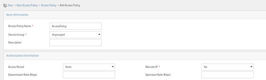
a. Add an access service:
i Select User Access Policy > Access Service from the navigation tree to open the access service page.
ii Click Add to open the page as shown in Figure 83.
iii Enter the service name IPoE_Server.
iv Select AccessPolicy from the default access policy list.
v Use the default settings for other parameters.
Figure 83 Adding an access service
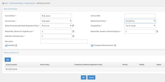
a. Add a user:
i Select User Management > Add User from the navigation tree to open the adding user page, as shown in Figure 84.
ii Enter the username IPoE_Web001 and the user ID 001.
iii Click OK.
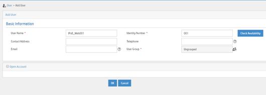
a. Add an access user:
i Select Access User > All Access Users from the navigation tree to open the access user page
ii Click Add to open the page as shown in Figure 85.
iii Select IPoE_Web001 for the username.
iv Enter the account name user1.
v Enter the password pass1.
vi Select the access service IPoE_Server.
Figure 85 Adding an access user

4. Configure the portal server (IMC PLAT 7.1):
|
|
NOTE: This example uses a portal server running IMC PLAT 7.1(E0303), IMC EIA 7.1(F0303), and IMC EIP 7.1(F0303). |
a. Configure the portal homepage:
i Select User Access Policy > Portal Service > Server from the navigation tree to open the portal server configuration page, as shown in Figure 86.
ii Click OK.
Figure 86 Portal server configuration page
a. Configure portal authentication source IP address range:
i Select User Access Policy > Portal Service > IP Group from the navigation tree to open the portal IP address group configuration page.
ii Click Add to open the page as shown in Figure 87.
iii Enter the IP group name IPoE_Web_User.
iv Enter the start IP address (192.168.0.1) and end IP address (192.168.0.255) of the IP group. Make sure the host IP address is in the IP group.
v Click OK.
Figure 87 Adding an IP address group
a. Add a portal device:
i Select User Access Policy > Portal Service > Device from the navigation tree to open the portal device configuration page.
ii Click Add to open the page as shown in Figure 88.
iii Enter the device name NAS.
iv Enter the IP address of the portal packets' outgoing interface GigabitEthernet 3/1/1 (4.4.4.2).
v Enter the key 123456
vi Select Directly Connect for access method.
vii Click OK.
Figure 88 Adding a portal device
a. Associate the portal device with the IP address group:
i Click the icon in the Port Group Information Management column of device NAS to open the port group configuration page, as shown in Figure 89.
ii Click Add to open the page as shown in Figure 90.
iii Enter the port group name group.
iv Select the configured IP address group IPoE_Web_User. Make sure the IP address used by the user to access the network is within this IP address group.
v Select Supported in the Transparent Authentication list.
vi Click OK.
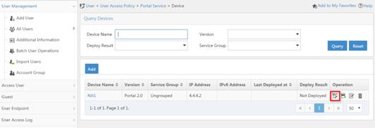
Figure 90 Port group configuration
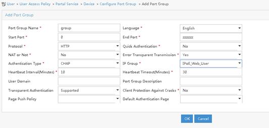
a. From the navigation tree, select User Access Manager > Service Parameters > Validate System Configuration to validate the settings.
5. Configure the MAC binding server on IMC PLAT 7.1
# Add an access policy:
a. Select User Access Policy > Access Policy from the navigation tree to open the access policy page.
b. Click Add to open the page as shown in Figure 91.
c. Enter the access policy name.
d. Select a service group.
e. Use the default settings for other parameters.
f. Click OK.
Figure 91 Adding an access policy
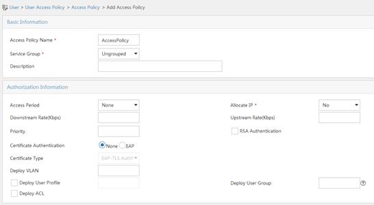
# Add an access service:
a. Select User Access Policy > Access Service from the navigation tree to open the access service page.
b. Click Add to open the page as shown in Figure 92.
c. Enter the service name.
d. Select the Transparent Authentication on Portal Endpoints option.
e. Use the default settings for other parameters.
f. Click OK.
Figure 92 Adding an access service
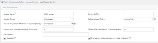
# Add an access user:
a. Select Access User > All Access Users from the navigation tree to open the access user page.
b. Click Add to open the page as shown in Figure 93.
c. Select an access user.
d. Set the password.
e. Select a value from the Max. Transparent Portal Bindings list.
f. Click OK.
Figure 93 Adding an access user
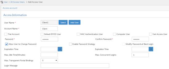
# Configure system parameters:
a. Select User Access Policy > Service Parameters > System Settings from the navigation tree to open the system settings page.
b.
Click the Configure
icon ![]() for User Endpoint Settings to open the
page as shown in Figure 94.
for User Endpoint Settings to open the
page as shown in Figure 94.
c. Select whether to enable transparent portal authentication on non-smart devices.
In this example, select Enable for Non-Terminal Authentication.
d. Click OK.
e.
Click the Configure
icon ![]() for Endpoint Aging Time to open the
page as shown in Figure 95.
for Endpoint Aging Time to open the
page as shown in Figure 95.
f. Set the endpoint aging time as needed.
This example uses the default value.
Figure 94 Configuring user endpoint settings
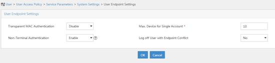
Figure 95 Setting the endpoint aging time
# Select User Access Policy > Service Parameters > Validate System Configuration from the navigation tree to validate the configurations.
Verifying the configuration
# Display IPoE session information to verify that the host has passed preauthentication.
[Device] display ip subscriber session verbose
Basic:
Description : -
Username : 0015e947f4d4
Domain : dm1
VPN instance : N/A
IP address : 192.168.0.2
User address type : N/A
MAC address : 0015-e947-f4d4
Service-VLAN/Customer-VLAN : -/-
Access interface : GE3/1/2
User ID : 0x3808001c
VPI/VCI(for ATM) : -/-
VSI Index : -
VSI link ID : -
VXLAN ID : -
DNS servers : 8.8.8.8
IPv6 DNS servers : N/A
DHCP lease : 86400 sec
DHCP remain lease : N/A
Access time : Aug 2 16:51:28 2016
Online time(hh:mm:ss) : 00:00:20
Service node : Slot 3 CPU 0
Authentication type : Web pre-auth
IPv4 access type : DHCP
IPv4 detect state : Detecting
State : Online
AAA:
ITA policy name : N/A
IP pool : pool1
IPv6 pool : N/A
Primary DNS server : N/A
Secondary DNS server : N/A
Primary IPv6 DNS server : N/A
Secondary IPv6 DNS server : N/A
Session idle cut : N/A
Session duration : N/A, remaining: N/A
Traffic quota : N/A
Traffic remained : N/A
Acct start-fail action : Online
Acct update-fail action : Online
Acct quota-out action : Offline
Dual-stack accounting mode : Merge
Max IPv4 multicast addresses: 4
IPv4 multicast address list : N/A
Max IPv6 multicast addresses: 4
IPv6 multicast address list : N/A
Accounting start time : Aug 2 16:51:28 2016
Redirect URL : http://4.4.4.5:8080/portal/
Subscriber ID : -
QoS:
User profile : N/A
Session group profile : N/A
User group ACL : web (active)
Inbound CAR : N/A
Outbound CAR : N/A
Inbound user priority : N/A
Outbound user priority : N/A
Flow statistic:
Uplink packets/bytes : 0/0
Downlink packets/bytes : 0/0
IPv6 uplink packets/bytes : 0/0
IPv6 downlink packets/bytes : 0/0
As shown in Figure 96, the Web login page opens after preauthentication. Enter the username and password on the page.
# Display IPoE session information to verify that the host has passed Web authentication and come online.
[Device] display ip subscriber session verbose
Basic:
Description : -
Username : user1
Domain : dm2
VPN instance : N/A
IP address : 192.168.0.2
User address type : N/A
MAC address : 0015-e947-f4d4
Service-VLAN/Customer-VLAN : -/-
Access interface : GE3/1/2
User ID : 0x3808001c
VPI/VCI(for ATM) : -/-
VSI Index : -
VSI link ID : -
VXLAN ID : -
DNS servers : 8.8.8.8
IPv6 DNS servers : N/A
DHCP lease : 86400 sec
DHCP remain lease : N/A
Access time : Aug 2 16:52:28 2016
Online time(hh:mm:ss) : 00:00:20
Service node : Slot 3 CPU 0
Authentication type : Web
IPv4 access type : DHCP
IPv4 detect state : Detecting
State : Online
AAA:
ITA policy name : N/A
IP pool : pool1
IPv6 pool : N/A
Primary DNS server : N/A
Secondary DNS server : N/A
Primary IPv6 DNS server : N/A
Secondary IPv6 DNS server : N/A
Session idle cut : N/A
Session duration : N/A, remaining: N/A
Traffic quota : N/A
Traffic remained : N/A
Acct start-fail action : Online
Acct update-fail action : Online
Acct quota-out action : Offline
Dual-stack accounting mode : Merge
Max IPv4 multicast addresses: 4
IPv4 multicast address list : N/A
Max IPv6 multicast addresses: 4
IPv6 multicast address list : N/A
Accounting start time : Aug 2 16:52:28 2016
Subscriber ID : -
QoS:
User profile : N/A
Session group profile : N/A
User group ACL : N/A
Inbound CAR : N/A
Outbound CAR : N/A
Inbound user priority : N/A
Outbound user priority : N/A
Flow statistic:
Uplink packets/bytes : 0/0
Downlink packets/bytes : 0/0
IPv6 uplink packets/bytes : 0/0
IPv6 downlink packets/bytes : 0/0
# Click Log Out on the Web login page as shown in Figure 96.
# Verify that the user returns to the preauthentication status.
[Device] display ip subscriber session verbose
Basic:
Description : -
Username : 0015e947f4d4
Domain : dm1
VPN instance : N/A
IP address : 192.168.0.2
User address type : N/A
MAC address : 0015-e947-f4d4
Service-VLAN/Customer-VLAN : -/-
Access interface : GE3/1/2
User ID : 0x3808001c
VPI/VCI(for ATM) : -/-
VSI Index : -
VSI link ID : -
VXLAN ID : -
DNS servers : 8.8.8.8
IPv6 DNS servers : N/A
DHCP lease : 86400 sec
DHCP remain lease : N/A
Access time : Aug 2 16:52:59 2016
Online time(hh:mm:ss) : 00:00:20
Service node : Slot 3 CPU 0
Authentication type : Web pre-auth
IPv4 access type : DHCP
IPv4 detect state : Detecting
State : Online
AAA:
ITA policy name : N/A
IP pool : pool1
IPv6 pool : N/A
Primary DNS server : N/A
Secondary DNS server : N/A
Primary IPv6 DNS server : N/A
Secondary IPv6 DNS server : N/A
Session idle cut : N/A
Session duration : N/A, remaining: N/A
Traffic quota : N/A
Traffic remained : N/A
Acct start-fail action : Online
Acct update-fail action : Online
Acct quota-out action : Offline
Dual-stack accounting mode : Merge
Max IPv4 multicast addresses: 4
IPv4 multicast address list : N/A
Max IPv6 multicast addresses: 4
IPv6 multicast address list : N/A
Accounting start time : Aug 2 16:52:59 2016
Redirect URL : http://4.4.4.5:8080/portal/
Subscriber ID : -
QoS:
User profile : N/A
Session group profile : N/A
User group ACL : web (active)
Inbound CAR : N/A
Outbound CAR : N/A
Inbound user priority : N/A
Outbound user priority : N/A
Flow statistic:
Uplink packets/bytes : 0/0
Downlink packets/bytes : 0/0
IPv6 uplink packets/bytes : 0/0
IPv6 downlink packets/bytes : 0/0
# Open the browser, and enter an address randomly, for example, http://63.1.1.240.
# Verify that the user has come online through IPoE Web authentication.
[Device] display ip subscriber session verbose
Basic:
Description : -
Username : 0015e947f4d4
Domain : dm2
VPN instance : N/A
IP address : 192.168.0.2
User address type : N/A
MAC address : 0015-e947-f4d4
Service-VLAN/Customer-VLAN : -/-
Access interface : GE3/1/2
User ID : 0x3808001c
VPI/VCI(for ATM) : -/-
VSI Index : -
VSI link ID : -
VXLAN ID : -
DNS servers : 8.8.8.8
IPv6 DNS servers : N/A
DHCP lease : 86400 sec
DHCP remain lease : N/A
Access time : Aug 2 16:52:59 2016
Online time(hh:mm:ss) : 00:00:20
Service node : Slot 3 CPU 0
Authentication type : Web
IPv4 access type : DHCP
IPv4 detect state : Detecting
State : Online
AAA:
ITA policy name : N/A
IP pool : pool1
IPv6 pool : N/A
Primary DNS server : N/A
Secondary DNS server : N/A
Primary IPv6 DNS server : N/A
Secondary IPv6 DNS server : N/A
Session idle cut : N/A
Session duration : N/A, remaining: N/A
Traffic quota : N/A
Traffic remained : N/A
Acct start-fail action : Online
Acct update-fail action : Online
Acct quota-out action : Offline
Dual-stack accounting mode : Merge
Max IPv4 multicast addresses: 4
IPv4 multicast address list : N/A
Max IPv6 multicast addresses: 4
IPv6 multicast address list : N/A
Accounting start time : Aug 2 16:53:28 2016
Subscriber ID : -
QoS:
User profile : N/A
Session group profile : N/A
User group ACL : N/A
Inbound CAR : N/A
Outbound CAR : N/A
Inbound user priority : N/A
Outbound user priority : N/A
Flow statistic:
Uplink packets/bytes : 0/0
Downlink packets/bytes : 0/0
IPv6 uplink packets/bytes : 0/0
IPv6 downlink packets/bytes : 0/0
Example: Configuring IPoE Layer 3 transparent MAC-trigger authentication
Network configuration
As shown in Figure 97, the host accesses the BRAS as a DHCP client though a Layer 3 network. The BRAS also acts as the DHCP server. A server installed with H3C IMC acts as the RADIUS server, the portal authentication server, the portal Web server, and the MAC binding server. The FTP server is an internal network server.
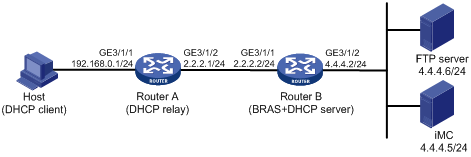
Procedure
1. Configure the DHCP relay agent:
# Enable DHCP.
<RouterA> system-view
[RouterA] dhcp enable
# Enable the DHCP relay agent to record client information in relay entries.
[RouterA] dhcp relay client-information record
# Disable the DHCP relay agent from periodically refreshing dynamic relay entries.
[RouterA] undo dhcp relay client-information refresh enable
# Enable DHCP server proxy on the DHCP relay agent and specify DHCP server address 2.2.2.2 on GigabitEthernet 3/1/1.
[RouterA] interface gigabitethernet 3/1/1
[RouterA–GigabitEthernet3/1/1] dhcp select relay proxy
[RouterA–GigabitEthernet3/1/1] dhcp relay server-address 2.2.2.2
[RouterA–GigabitEthernet3/1/1] quit
# Configure the default route from the DHCP relay agent to the BRAS.
[RouterA] ip route-static 0.0.0.0 24 2.2.2.2
2. Configure Router B:
a. Configure IP addresses for interfaces. (Details not shown.)
b. Configure the DHCP server:
# Enable DHCP.
<RouterB> system-view
[RouterB] dhcp enable
# Create an IP address pool named pool1 and enter its view.
[RouterB] dhcp server ip-pool pool1
# Specify primary subnet 192.168.0.0/24 for dynamic allocation in DHCP address pool pool1.
[RouterB-dhcp-pool-pool1] network 192.168.0.0 24
# Specify gateway address 192.168.0.1 in DHCP address pool pool1.
[RouterB-dhcp-pool-pool1] gateway-list 192.168.0.1
# Specify DNS server address 8.8.8.8 in DHCP address pool pool1.
[RouterB-dhcp-pool-pool1] dns-list 8.8.8.8
# Exclude IP address 192.168.0.1 from dynamic allocation in DHCP address pool pool1.
[RouterB-dhcp-pool-pool1] forbidden-ip 192.168.0.1
[RouterB-dhcp-pool-pool1] quit
# Configure a static route to the DHCP relay agent.
[RouterB] ip route-static 192.168.0.0 24 2.2.2.1
c. Configure the IP address of the portal authentication server newpt as 4.4.4.5 and the plaintext key 123456.
[RouterB] portal server newpt
[RouterB-portal-server-newpt] ip 4.4.4.5 key simple 123456
[RouterB-portal-server-newpt] quit
d. Specify 11111 as the HTTPS redirect listening port number.
[RouterB] http-redirect https-port 11111
e. Create a local user group named web.
[RouterB] user-group web
New user group added.
[Device-ugroup-web] quit
f. Configure ACLs for preauthentication:
# Create an IPv4 advanced ACL named web_permit. Configure a rule to permit all packets destined for the portal server from users in user group web.
[RouterB] acl advanced name web_permit
[RouterB-acl-ipv4-adv-web_permit] rule 0 permit ip destination 4.4.4.5 0 user-group web
[RouterB-acl-ipv4-adv-web_permit] quit
# Create an IPv4 advanced ACL named neiwang. Configure a rule to permit all packets destined for the internal network server from users in user group web.
[RouterB] acl advanced name neiwang
[RouterB-acl-ipv4-adv-neiwang] rule 0 permit ip destination 4.4.4.6 0 user-group web
[RouterB-acl-ipv4-adv-neiwang] quit
# Create an IPv4 advanced ACL named web_http. Configure a rule to permit TCP packets with the destination port 80 (HTTP packets) from users in user group web.
[RouterB] acl advanced name web_http
[RouterB-acl-ipv4-adv-web_http] rule 0 permit tcp destination-port eq www user-group web
[RouterB-acl-ipv4-adv-web_http] quit
# Create an IPv4 advanced ACL named web_https, and configure a rule to permit TCP packets with the destination port 443 (HTTPS packets) from users in user group web.
[RouterB] acl advanced name web_https
[RouterB-acl-ipv4-adv-web_https] rule 0 permit tcp destination-port eq 443 user-group web
[RouterB-acl-ipv4-adv-web_https] quit
# Create an IPv4 advanced ACL named ip, and configure a rule to permit IP packets from users in user group web.
[RouterB] acl advanced name ip
[RouterB-acl-ipv4-adv-ip] rule 0 permit ip user-group web
[RouterB-acl-ipv4-adv-ip] quit
# Create an IPv4 advanced ACL named neiwang_out, and configure a rule to permit IP packets from the internal network server in user group web.
[RouterB] acl advanced name neiwang_out
[RouterB-acl-ipv4-adv-neiwang_out] rule 0 permit ip source 4.4.4.6 0 user-group web
[RouterB-acl-ipv4-adv-neiwang_out] quit
# Create an IPv4 advanced ACL named web_out, and configure a rule to permit IP packets from the portal server in user group web.
[RouterB] acl advanced name web_out
[RouterB-acl-ipv4-adv-web_out] rule 0 permit ip source 4.4.4.5 0 user-group web
[RouterB-acl-ipv4-adv-web_out] quit
g. Configure QoS traffic classes for preauthentication users:
# Create the traffic class web_permit and specify ACL web_permit as the match criterion.
[RouterB] traffic classifier web_permit operator and
[RouterB-classifier-web_permit] if-match acl name web_permit
[RouterB-classifier-web_permit] quit
# Create the traffic class neiwang and specify ACL neiwang as the match criterion.
[RouterB] traffic classifier neiwang operator and
[RouterB-classifier-neiwang] if-match acl name neiwang
[RouterB-classifier-neiwang] quit
# Create the traffic class web_http and specify ACL web_http as the match criterion.
[RouterB] traffic classifier web_http operator and
[RouterB-classifier-web_http] if-match acl name web_http
[RouterB-classifier-web_http] quit
# Create the traffic class web_https and specify ACL web_https as the match criterion.
[RouterB] traffic classifier web_https operator and
[RouterB-classifier-web_https] if-match acl name web_https
[RouterB-classifier-web_https] quit
# Create the traffic class ip_cpu and specify ACL ip as the match criterion.
[Device] traffic classifier ip_cpu operator and
[Device-classifier-ip_cpu] if-match acl name ip
[Device-classifier-ip_cpu] quit
# Create the traffic class ip_deny and specify ACL ip as the match criterion.
[Device] traffic classifier ip_deny operator and
[Device-classifier-ip_deny] if-match acl name ip
[Device-classifier-ip_deny] quit
# Create the traffic class neiwang_out and specify ACL neiwang_out as the match criterion.
[RouterB] traffic classifier neiwang_out operator and
[RouterB-classifier-neiwang_out] if-match acl name neiwang_out
[RouterB-classifier-neiwang_out] quit
# Create the traffic class web_out and specify ACL web_out as the match criterion.
[RouterB] traffic classifier web_out operator and
[RouterB-classifier-web_out] if-match acl name web_out
[RouterB-classifier-web_out] quit
h. Configure QoS traffic behaviors:
# Configure the traffic behavior web_permit to permit traffic to pass through without rate limiting or accounting.
[RouterB] traffic behavior web_permit
[RouterB-behavior-web_permit] filter permit
[RouterB-behavior-web_permit] free account
[RouterB-behavior-web_permit] quit
# Configure the traffic behavior neiwang to permit traffic to pass through.
[RouterB] traffic behavior neiwang
[RouterB-behavior-neiwang] filter permit
[RouterB-behavior-neiwang] quit
# Configure the traffic behavior web_http to redirect HTTP packets to the CPU.
[RouterB] traffic behavior web_http
[RouterB-behavior-web_http] redirect http-to-cpu
[RouterB-behavior-web_http] quit
# Configure the traffic behavior web_https to redirect HTTPS packets to the CPU.
[RouterB] traffic behavior web_https
[RouterB-behavior-web_https] redirect https-to-cpu
[RouterB-behavior-web_https] quit
# Configure the traffic behavior web_cpu to redirect traffic to the CPU.
[Device] traffic behavior web_cpu
[Device-behavior-web_cpu] redirect cpu
[Device-behavior-web_cpu] quit
# Configure the traffic behavior web_deny to deny traffic.
[RouterB] traffic behavior web_deny
[RouterB-behavior-web_deny] filter deny
[RouterB-behavior-web_deny] free account
[RouterB-behavior-web_deny] quit
# Configure the traffic behavior neiwang_out to permit traffic to pass through.
[RouterB] traffic behavior neiwang_out
[RouterB-behavior-neiwang_out] filter permit
[RouterB-behavior-neiwang_out] quit
# Configure the traffic behavior web_out to permit traffic without rate limiting or traffic accounting.
[RouterB] traffic behavior web_out
[RouterB-behavior-web_out] filter permit
[RouterB-behavior-web_out] free account
[RouterB-behavior-web_out] quit
i. Configure the QoS policies:
# Create a QoS policy named web.
[RouterB] qos policy web
# Associate the traffic class web_permit with the traffic behavior web_permit.
[RouterB-qospolicy-web] classifier web_permit behavior web_permit
# Associate the traffic class neiwang with the traffic behavior neiwang.
[RouterB-qospolicy-web] classifier neiwang behavior neiwang
# Associate the traffic class web_http with the traffic behavior web_http.
[RouterB-qospolicy-web] classifier web_http behavior web_http
# Associate the traffic class web_https with the traffic behavior web_https.
[RouterB-qospolicy-web] classifier web_https behavior web_https
# Associate the traffic class ip_cpu with the traffic behavior web_cpu.
[RouterB-qospolicy-web] classifier ip_cpu behavior web_cpu
# Associate the traffic class ip_deny with the traffic behavior web_deny.
[RouterB-qospolicy-web] classifier ip_deny behavior web_deny
[RouterB-qospolicy-web] quit
# Configure a QoS policy named out.
[RouterB] qos policy out
# Associate the traffic class web_out with the traffic behavior web_out. Associate the traffic class neiwang_out with the traffic behavior neiwang_out. Associate the traffic class ip_deny with the traffic behavior web_deny.
[RouterB-qospolicy-out] classifier web_out behavior web_out
[RouterB-qospolicy-out] classifier neiwang_out behavior neiwang_out
[RouterB-qospolicy-out] classifier ip_deny behavior web_deny
[RouterB-qospolicy-out] quit
j. Apply the QoS policies:
# Apply the QoS Policy web to the inbound traffic globally.
[RouterB] qos apply policy web global inbound
# Apply the QoS Policy out to the outbound traffic globally.
[RouterB] qos apply policy out global outbound
k. Configure a RADIUS scheme:
# Create a RADIUS scheme named rs1 and enter its view.
[RouterB] radius scheme rs1
# Configure primary servers and keys for authentication and accounting.
[RouterB-radius-rs1] primary authentication 4.4.4.5
[RouterB-radius-rs1] primary accounting 4.4.4.5
[RouterB-radius-rs1] key authentication simple radius
[RouterB-radius-rs1] key accounting simple radius
# Exclude the ISP name from the username sent to the RADIUS server.
[RouterB-radius-rs1] user-name-format without-domain
[RouterB-radius-rs1] quit
l. Configure the preauthentication ISP domain and Web authentication ISP domain:
# Configure the ISP domain dm1 for IPoE user preauthentication.
[RouterB] domain name dm1
[RouterB-isp-dm1] authentication ipoe none
[RouterB-isp-dm1] authorization ipoe none
[RouterB-isp-dm1] accounting ipoe none
# Configure the authorized IP address pool and user group in ISP domain dm1.
[RouterB-isp-dm1] authorization-attribute user-group web
[RouterB-isp-dm1] authorization-attribute ip-pool pool1
# Configure the Web authentication page URL in ISP domain dm1.
[RouterB-isp-dm1] web-server url http://4.4.4.5:8080/portal/
[RouterB-isp-dm1] quit
# Configure the ISP domain dm2 for IPoE user Web authentication.
[RouterB] domain name dm2
[RouterB-isp-dm2] authentication ipoe radius-scheme rs1
[RouterB-isp-dm2] authorization ipoe radius-scheme rs1
[RouterB-isp-dm2] accounting ipoe radius-scheme rs1
[RouterB-isp-dm2] quit
m. Configure basic IPoE transparent authentication:
# Enable IPoE and configure Layer 3 access mode on GigabitEthernet 3/1/1.
[RouterB] interface gigabitethernet 3/1/1
[RouterB–GigabitEthernet3/1/1] ip subscriber routed enable
# Configure Web authentication for IPoE users on GigabitEthernet 3/1/1.
[RouterB–GigabitEthernet3/1/1] ip subscriber authentication-method web
The operation may cut all users on this interface. Continue?[Y/N]:y
# Configure the ISP domain dm1 for preauthentication and the ISP domain dm2 for Web authentication on GigabitEthernet 3/1/1.
[RouterB–GigabitEthernet3/1/1] ip subscriber pre-auth domain dm1
[RouterB–GigabitEthernet3/1/1] ip subscriber web-auth domain dm2
# Configure online detection on GigabitEthernet 3/1/1. The maximum number of detection attempts is 5, the detection timer is 120 seconds, and the detection packet type is ICMP.
The detection packet type is ARP by default. To use Layer 3 transparent authentication, you must set the detection packet type to ICMP or disable online detection.
[RouterB–GigabitEthernet3/1/1] ip subscriber user-detect ip icmp retry 5 interval 120
[RouterB–GigabitEthernet3/1/1] quit
n. (Optional.) Allow abnormally logged out IPoE DHCP users to come online again:
|
|
NOTE: · To allow abnormally logged out DHCP users to come online again through packet initiation in the network, configure this feature. · This section describes only the key configuration for allowing abnormally logged out users to come online again. For how this feature works and the configuration restrictions and guidelines for this feature, see "Allowing abnormally logged out DHCP users to come online again through packet initiation." |
# Enable DHCP packet initiation.
[Device] interface gigabitethernet 3/1/2
[Device–GigabitEthernet3/1/2] ip subscriber initiator dhcp enable
# Enable ARP packet initiation.
[Device–GigabitEthernet3/1/2] ip subscriber initiator arp enable
# Enable unclassified-IP packet initiation.
[Device–GigabitEthernet3/1/2] ip subscriber initiator unclassified-ip enable matching-user
[Device–GigabitEthernet3/1/2] quit
o. (Optional.) Configure roaming for IPoE DHCP users:
|
|
NOTE: · Configure this feature in a network where users need roaming. · This section describes only the key configuration for DHCP user roaming. For how this feature works and the configuration restrictions and guidelines for this feature, see "Enabling roaming for IPoE individual users." |
# Enable DHCP packet initiation.
[Device] interface gigabitethernet 3/1/2
[Device–GigabitEthernet3/1/2] ip subscriber initiator dhcp enable
# Enable ARP packet initiation.
[Device–GigabitEthernet3/1/2] ip subscriber initiator arp enable
# Enable unclassified-IP packet initiation.
[Device–GigabitEthernet3/1/2] ip subscriber initiator unclassified-ip enable matching-user
# Enable roaming for IPoE individual users.
[Device–GigabitEthernet3/1/2] ip subscriber roaming enable
# Configure DHCP on GigabitEthernet 3/1/2 to release the online lease for a MAC address of a user and then allocate an IP address to the user after GigabitEthernet 3/1/2 receives a DHCP-DISCOVER packet from an online user whose physical location changes and MAC address does not change.
[Device–GigabitEthernet3/1/2] dhcp session-mismatch action fast-renew
[Device–GigabitEthernet3/1/2] quit
p. Configure MAC-based quick portal authentication:
# Create MAC binding server mts.
[RouterB] portal mac-trigger server mts
# Specify the IP address of the MAC binding server as 4.4.4.5.
[RouterB-portal-mac-trigger-server-mts] ip 4.4.4.5
[RouterB-portal-mac-trigger-server-mts] quit
# Specify the MAC binding server mts on GigabitEthernet 3/1/1.
[RouterB] interface gigabitethernet 3/1/1
[RouterB–GigabitEthernet3/1/1] portal apply mac-trigger-server mts
[RouterB–GigabitEthernet3/1/1] quit
3. Configure the RADIUS server:
a. Configure the access device:
i Log in to the IMC platform and click the User tab.
ii Select User Access Policy > Access Device Management > Access Device from the navigation tree to open the access device configuration page.
iii Click Add to open the page as shown in Figure 98.
iv Enter the shared key radius.
v Use the default settings for other parameters.
Figure 98 Adding an access device
vi Click Add Manually in the Device List area to open the page as shown in Figure 99.
vii Enter the access device's IP address 4.4.4.2.
viii Click OK.
Figure 99 Manually adding an access device
a. Add an access policy:
i Select User Access Policy > Access Policy from the navigation tree to open the access policy page.
ii Click Add to open the page as shown in Figure 100.
iii Enter the access policy name AccessPolicy.
iv Use the default settings for other parameters.
Figure 100 Adding an access policy
a. Add an access service:
i Select User Access Policy > Access Service from the navigation tree to open the access service page.
ii Click Add to open the page as shown in Figure 101.
iii Enter the service name IPoE_Server.
iv Select AccessPolicy from the default access policy list.
v Use the default settings for other parameters.
Figure 101 Adding an access service

a. Add a user:
i Select User Management > Add User from the navigation tree to open the adding user page, as shown in Figure 102.
ii Enter the username IPoE_Web001 and the user ID 001.
iii Click OK.
a. Add an access user:
i Select Access User > All Access Users from the navigation tree to open the access user page
ii Click Add to open the page as shown in Figure 103.
iii Select IPoE_Web001 for the username.
iv Enter the account name user1.
v Enter the password pass1.
vi Select the access service IPoE_Server.
Figure 103 Adding an access user
4. Configure the portal server (IMC PLAT 7.1):
|
|
NOTE: This example uses a portal server running IMC PLAT 7.1(E0303), IMC EIA 7.1(F0303), and IMC EIP 7.1(F0303). |
a. Configure the portal homepage:
i Select User Access Policy > Portal Service > Server from the navigation tree to open the portal server configuration page, as shown in Figure 104.
ii Click OK.
Figure 104 Portal server configuration page
a. Configure portal authentication source IP address range:
i Select User Access Policy > Portal Service > IP Group from the navigation tree to open the portal IP address group configuration page.
ii Click Add to open the page as shown in Figure 105.
iii Enter the IP group name IPoE_Web_User.
iv Enter the start IP address (192.168.0.1) and end IP address (192.168.0.255) of the IP group. Make sure the host IP address is in the IP group.
v Click OK.
Figure 105 Adding an IP address group
a. Add a portal device:
i Select User Access Policy > Portal Service > Device from the navigation tree to open the portal device configuration page.
ii Click Add to open the page as shown in Figure 106.
iii Enter the device name NAS.
iv Enter the IP address of the portal packets' outgoing interface GigabitEthernet 3/1/2 (4.4.4.2).
v Enter the key 123456.
vi Select Directly Connect for access method.
vii Click OK.
Figure 106 Adding a portal device

a. Associate the portal device with the IP address group:
i Click the icon in the Port Group Information Management column of device NAS to open the port group configuration page, as shown in Figure 107.
ii Click Add to open the page as shown in Figure 108.
iii Enter the port group name group.
iv Select the configured IP address group IPoE_Web_User. Make sure the IP address used by the user to access the network is within this IP address group.
v Select Supported in the Transparent Authentication list.
vi Click OK.
Figure 108 Port group configuration

a. From the navigation tree, select User Access Manager > Service Parameters > Validate System Configuration to validate the settings.
5. Configure the MAC binding server on IMC PLAT 7.1
# Add an access policy:
a. Select User Access Policy > Access Policy from the navigation tree to open the access policy page.
b. Click Add to open the page as shown in Figure 109.
c. Enter the access policy name.
d. Select a service group.
e. Use the default settings for other parameters.
f. Click OK.
Figure 109 Adding an access policy

# Add an access service:
a. Select User Access Policy > Access Service from the navigation tree to open the access service page.
b. Click Add to open the page as shown in Figure 110.
c. Enter the service name.
d. Select the Transparent Authentication on Portal Endpoints option.
e. Use the default settings for other parameters.
f. Click OK.
Figure 110 Adding an access service
# Add an access user:
a. Select Access User > All Access Users from the navigation tree to open the access user page.
b. Click Add to open the page as shown in Figure 111.
c. Select an access user.
d. Set the password.
e. Select a value from the Max. Transparent Portal Bindings list.
f. Click OK.
Figure 111 Adding an access user
# Configure system parameters:
a. Select User Access Policy > Service Parameters > System Settings from the navigation tree to open the system settings page.
b.
Click the Configure
icon ![]() for User Endpoint Settings to open the
page as shown in Figure 112.
for User Endpoint Settings to open the
page as shown in Figure 112.
c. Select whether to enable transparent portal authentication on non-smart devices.
In this example, select Enable for Non-Terminal Authentication.
d. Click OK.
e.
Click the Configure
icon ![]() for Endpoint Aging Time to open the
page as shown in Figure 113.
for Endpoint Aging Time to open the
page as shown in Figure 113.
f. Set the endpoint aging time as needed.
This example uses the default value.
Figure 112 Configuring user endpoint settings
Figure 113 Setting the endpoint aging time
# Select User Access Policy > Service Parameters > Validate System Configuration from the navigation tree to validate the configurations.
Verifying the configuration
# Display IPoE session information to verify that the host has passed preauthentication.
[RouterB] display ip subscriber session verbose
Basic:
Description : -
Username : 0015e947f4d4
Domain : dm1
VPN instance : N/A
IP address : 192.168.0.2
User address type : N/A
MAC address : 0015-e947-f4d4
Service-VLAN/Customer-VLAN : -/-
Access interface : GE3/1/1
User ID : 0x3808001c
VPI/VCI(for ATM) : -/-
VSI Index : -
VSI link ID : -
VXLAN ID : -
DNS servers : 8.8.8.8
IPv6 DNS servers : N/A
DHCP lease : 86400 sec
DHCP remain lease : N/A
Access time : Aug 2 16:51:28 2016
Online time(hh:mm:ss) : 00:00:20
Service node : Slot 3 CPU 0
Authentication type : Web pre-auth
IPv4 access type : DHCP
IPv4 detect state : Detecting
State : Online
AAA:
ITA policy name : N/A
IP pool : pool1
IPv6 pool : N/A
Primary DNS server : N/A
Secondary DNS server : N/A
Primary IPv6 DNS server : N/A
Secondary IPv6 DNS server : N/A
Session idle cut : N/A
Session duration : N/A, remaining: N/A
Traffic quota : N/A
Traffic remained : N/A
Acct start-fail action : Online
Acct update-fail action : Online
Acct quota-out action : Offline
Dual-stack accounting mode : Merge
Max IPv4 multicast addresses: 4
IPv4 multicast address list : N/A
Max IPv6 multicast addresses: 4
IPv6 multicast address list : N/A
Accounting start time : Aug 2 16:51:28 2016
Redirect URL : http://4.4.4.5:8080/portal/
Subscriber ID : -
QoS:
User profile : N/A
Session group profile : N/A
User group ACL : web (active)
Inbound CAR : N/A
Outbound CAR : N/A
Inbound user priority : N/A
Outbound user priority : N/A
Flow statistic:
Uplink packets/bytes : 0/0
Downlink packets/bytes : 0/0
IPv6 uplink packets/bytes : 0/0
IPv6 downlink packets/bytes : 0/0
As shown in Figure 114, the Web login page opens after preauthentication. Enter the username and password on the page.

# Display IPoE session information to verify that the host has passed Web authentication and come online.
[RouterB] display ip subscriber session verbose
Basic:
Description : -
Username : user1
Domain : dm2
VPN instance : N/A
IP address : 192.168.0.2
User address type : N/A
MAC address : 0015-e947-f4d4
Service-VLAN/Customer-VLAN : -/-
Access interface : GE3/1/1
User ID : 0x3808001c
VPI/VCI(for ATM) : -/-
VSI Index : -
VSI link ID : -
VXLAN ID : -
DNS servers : 8.8.8.8
IPv6 DNS servers : N/A
DHCP lease : 86400 sec
DHCP remain lease : N/A
Access time : Aug 2 16:52:28 2016
Online time(hh:mm:ss) : 00:00:20
Service node : Slot 3 CPU 0
Authentication type : Web
IPv4 access type : DHCP
IPv4 detect state : Detecting
State : Online
AAA:
ITA policy name : N/A
IP pool : pool1
IPv6 pool : N/A
Primary DNS server : N/A
Secondary DNS server : N/A
Primary IPv6 DNS server : N/A
Secondary IPv6 DNS server : N/A
Session idle cut : N/A
Session duration : N/A, remaining: N/A
Traffic quota : N/A
Traffic remained : N/A
Acct start-fail action : Online
Acct update-fail action : Online
Acct quota-out action : Offline
Dual-stack accounting mode : Merge
Max IPv4 multicast addresses: 4
IPv4 multicast address list : N/A
Max IPv6 multicast addresses: 4
IPv6 multicast address list : N/A
Accounting start time : Aug 2 16:52:28 2016
Subscriber ID : -
QoS:
User profile : N/A
Session group profile : N/A
User group ACL : N/A
Inbound CAR : N/A
Outbound CAR : N/A
Inbound user priority : N/A
Outbound user priority : N/A
Flow statistic:
Uplink packets/bytes : 0/0
Downlink packets/bytes : 0/0
IPv6 uplink packets/bytes : 0/0
IPv6 downlink packets/bytes : 0/0
# Click Log Out on the Web login page as shown in Figure 114.
# Verify that the user returns to the preauthentication status.
[RouterB] display ip subscriber session verbose
Basic:
Description : -
Username : 0015e947f4d4
Domain : dm1
VPN instance : N/A
IP address : 192.168.0.2
User address type : N/A
MAC address : 0015-e947-f4d4
Service-VLAN/Customer-VLAN : -/-
Access interface : GE3/1/1
User ID : 0x3808001c
VPI/VCI(for ATM) : -/-
VSI Index : -
VSI link ID : -
VXLAN ID : -
DNS servers : 8.8.8.8
IPv6 DNS servers : N/A
DHCP lease : 86400 sec
DHCP remain lease : N/A
Access time : Aug 2 16:52:59 2016
Online time(hh:mm:ss) : 00:00:20
Service node : Slot 3 CPU 0
Authentication type : Web pre-auth
IPv4 access type : DHCP
IPv4 detect state : Detecting
State : Online
AAA:
ITA policy name : N/A
IP pool : pool1
IPv6 pool : N/A
Primary DNS server : N/A
Secondary DNS server : N/A
Primary IPv6 DNS server : N/A
Secondary IPv6 DNS server : N/A
Session idle cut : N/A
Session duration : N/A, remaining: N/A
Traffic quota : N/A
Traffic remained : N/A
Acct start-fail action : Online
Acct update-fail action : Online
Acct quota-out action : Offline
Dual-stack accounting mode : Merge
Max IPv4 multicast addresses: 4
IPv4 multicast address list : N/A
Max IPv6 multicast addresses: 4
IPv6 multicast address list : N/A
Accounting start time : Aug 2 16:52:59 2016
Redirect URL : http://4.4.4.5:8080/portal/
Subscriber ID : -
QoS:
User profile : N/A
Session group profile : N/A
User group ACL : web (active)
Inbound CAR : N/A
Outbound CAR : N/A
Inbound user priority : N/A
Outbound user priority : N/A
Flow statistic:
Uplink packets/bytes : 0/0
Downlink packets/bytes : 0/0
IPv6 uplink packets/bytes : 0/0
IPv6 downlink packets/bytes : 0/0
# Open the browser, and enter an address randomly, for example, http://63.1.1.240.
# Verify that the user has come online through IPoE Web authentication.
[Router] display ip subscriber session verbose
Basic:
Description : -
Username : 0015e947f4d4
Domain : dm2
VPN instance : N/A
IP address : 192.168.0.2
User address type : N/A
MAC address : 0015-e947-f4d4
Service-VLAN/Customer-VLAN : -/-
Access interface : GE3/1/1
User ID : 0x3808001c
VPI/VCI(for ATM) : -/-
VSI Index : -
VSI link ID : -
VXLAN ID : -
DNS servers : 8.8.8.8
IPv6 DNS servers : N/A
DHCP lease : 86400 sec
DHCP remain lease : N/A
Access time : Aug 2 16:52:59 2016
Online time(hh:mm:ss) : 00:00:20
Service node : Slot 3 CPU 0
Authentication type : Web
IPv4 access type : DHCP
IPv4 detect state : Detecting
State : Online
AAA:
ITA policy name : N/A
IP pool : pool1
IPv6 pool : N/A
Primary DNS server : N/A
Secondary DNS server : N/A
Primary IPv6 DNS server : N/A
Secondary IPv6 DNS server : N/A
Session idle cut : N/A
Session duration : N/A, remaining: N/A
Traffic quota : N/A
Traffic remained : N/A
Acct start-fail action : Online
Acct update-fail action : Online
Acct quota-out action : Offline
Dual-stack accounting mode : Merge
Max IPv4 multicast addresses: 4
IPv4 multicast address list : N/A
Max IPv6 multicast addresses: 4
IPv6 multicast address list : N/A
Accounting start time : Aug 2 16:53:28 2016
Subscriber ID : -
QoS:
User profile : N/A
Session group profile : N/A
User group ACL : N/A
Inbound CAR : N/A
Outbound CAR : N/A
Inbound user priority : N/A
Outbound user priority : N/A
Flow statistic:
Uplink packets/bytes : 0/0
Downlink packets/bytes : 0/0
IPv6 uplink packets/bytes : 0/0
IPv6 downlink packets/bytes : 0/0
Example: Configuring IPoE Layer 2 transparent MAC authentication
Network configuration
As shown in Figure 115, the host accesses the BRAS as a DHCP client though a Layer 2 device. It obtains configuration information from the DHCP server through the BRAS. The BRAS performs AAA for the host through the RADIUS server. A server installed with H3C IMC acts as the portal authentication server and the portal Web server. A RADIUS server that supports MAC binding acts as the authentication, authorization, and accounting server and performs MAC binding. The FTP server is an internal network server.
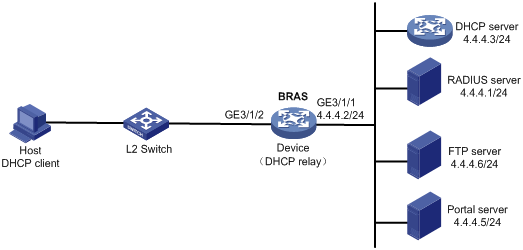
Procedure
1. Configure the DHCP server:
# Enable DHCP.
<DHCP-server> system-view
[DHCP-server] dhcp enable
# Create an IP address pool named pool1 and enter its view.
[DHCP-server] dhcp server ip-pool pool1
# Specify primary subnet 192.168.0.0/24 for dynamic allocation in DHCP address pool pool1.
[DHCP-server-dhcp-pool-pool1] network 192.168.0.0 24
# Specify gateway address 192.168.0.1 in DHCP address pool pool1.
[DHCP-server-dhcp-pool-pool1] gateway-list 192.168.0.1
# Specify DNS server address 8.8.8.8 in DHCP address pool pool1.
[DHCP-server-dhcp-pool-pool1] dns-list 8.8.8.8
# Exclude IP address 192.168.0.1 from dynamic allocation in DHCP address pool pool1.
[DHCP-server-dhcp-pool-pool1] forbidden-ip 192.168.0.1
[DHCP-server-dhcp-pool-pool1] quit
# Configure a static route to specify the next hop of DHCP replies destined to network segment 192.168.0.0 as the IP address of the interface connected to the DHCP client, 4.4.4.2.
[DHCP-server] ip route-static 192.168.0.0 24 4.4.4.2
# Configure a static route to specify the next hop of DHCP replies destined to network segment 192.168.0.0 as the IP address of the interface connected to the DHCP client, 4.4.4.2.
[DHCP-server] ip route-static 192.168.0.0 24 4.4.4.2
2. Configure the BRAS:
a. Configure IP addresses for interfaces. (Details not shown.)
b. Configure the DHCP relay agent:
# Enable DHCP.
<Device> system-view
[Device] dhcp enable
# Enable the DHCP relay agent to record client information in relay entries.
[Device] dhcp relay client-information record
# Disable the DHCP relay agent from periodically refreshing dynamic relay entries.
[Device] undo dhcp relay client-information refresh enable
# Enable DHCP server proxy on the DHCP relay agent on GigabitEthernet 3/1/2.
[Device] interface gigabitethernet 3/1/2
[Device–GigabitEthernet3/1/2] dhcp select relay proxy
[Device–GigabitEthernet3/1/2] quit
# Create an IP address pool named pool1 for the DHCP relay agent.
[Device] dhcp server ip-pool pool1
# Specify gateway address 192.168.0.1 in DHCP address pool pool1.
[Device-dhcp-pool-pool1] gateway-list 192.168.0.1 export-route
# Specify DHCP server 4.4.4.3 in DHCP address pool pool1.
[Device-dhcp-pool-pool1] remote-server 4.4.4.3
[Device-dhcp-pool-pool1] quit
c. Configure the IP address of the portal authentication server newpt as 4.4.4.5 and the plaintext key 123456.
[Device] portal server newpt
[Device-portal-server-newpt] ip 4.4.4.5 key simple 123456
[Device-portal-server-newpt] quit
d. Specify 11111 as the HTTPS redirect listening port number.
[Device] http-redirect https-port 11111
e. Create a local user group named web.
[Device] user-group web
New user group added.
[Device-ugroup-web] quit
f. Configure ACLs for preauthentication:
# Create an IPv4 advanced ACL named web_permit. Configure a rule to permit all packets destined for the portal server from users in user group web.
[Device] acl advanced name web_permit
[Device-acl-ipv4-adv-web_permit] rule 0 permit ip destination 4.4.4.5 0 user-group web
[Device-acl-ipv4-adv-web_permit] quit
# Create an IPv4 advanced ACL named neiwang. Configure a rule to permit all packets destined for the internal network server from users in user group web.
[Device] acl advanced name neiwang
[Device-acl-ipv4-adv-neiwang] rule 0 permit ip destination 4.4.4.6 0 user-group web
[Device-acl-ipv4-adv-neiwang] quit
# Create an IPv4 advanced ACL named web_http. Configure a rule to permit TCP packets with the destination port 80 (HTTP packets) from users in user group web.
[Device] acl advanced name web_http
[Device-acl-ipv4-adv-web_http] rule 0 permit tcp destination-port eq www user-group web
[Device-acl-ipv4-adv-web_http] quit
# Create an IPv4 advanced ACL named web_https, and configure a rule to permit TCP packets with the destination port 443 (HTTPS packets) from users in user group web.
[Device] acl advanced name web_https
[Device-acl-ipv4-adv-web_https] rule 0 permit tcp destination-port eq 443 user-group web
[Device-acl-ipv4-adv-web_https] quit
# Create an IPv4 advanced ACL named ip, and configure a rule to permit IP packets from users in user group web.
[Device] acl advanced name ip
[Device-acl-ipv4-adv-ip] rule 0 permit ip user-group web
[Device-acl-ipv4-adv-ip] quit
# Create an IPv4 advanced ACL named neiwang_out, and configure a rule to permit IP packets from the internal network server in user group web.
[Device] acl advanced name neiwang_out
[Device-acl-ipv4-adv-neiwang_out] rule 0 permit ip source 4.4.4.6 0 user-group web
[Device-acl-ipv4-adv-neiwang_out] quit
# Create an IPv4 advanced ACL named web_out, and configure a rule to permit IP packets from the portal server in user group web.
[Device] acl advanced name web_out
[Device-acl-ipv4-adv-web_out] rule 0 permit ip source 4.4.4.5 0 user-group web
[Device-acl-ipv4-adv-web_out] quit
g. Configure QoS traffic classes for preauthentication users:
# Create the traffic class web_permit and specify ACL web_permit as the match criterion.
[Device] traffic classifier web_permit operator and
[Device-classifier-web_permit] if-match acl name web_permit
[Device-classifier-web_permit] quit
# Create the traffic class neiwang and specify ACL neiwang as the match criterion.
[Device] traffic classifier neiwang operator and
[Device-classifier-neiwang] if-match acl name neiwang
[Device-classifier-neiwang] quit
# Create the traffic class web_http and specify ACL web_http as the match criterion.
[Device] traffic classifier web_http operator and
[Device-classifier-web_http] if-match acl name web_http
[Device-classifier-web_http] quit
# Create the traffic class web_https and specify ACL web_https as the match criterion.
[Device] traffic classifier web_https operator and
[Device-classifier-web_https] if-match acl name web_https
[Device-classifier-web_https] quit
# Create the traffic class ip_cpu and specify ACL ip as the match criterion.
[Device] traffic classifier ip_cpu operator and
[Device-classifier-ip_cpu] if-match acl name ip
[Device-classifier-ip_cpu] quit
# Create the traffic class ip_deny and specify ACL ip as the match criterion.
[Device] traffic classifier ip_deny operator and
[Device-classifier-ip_deny] if-match acl name ip
[Device-classifier-ip_deny] quit
# Create the traffic class web_out and specify ACL web_out as the match criterion.
[Device] traffic classifier web_out operator and
[Device-classifier-web_out] if-match acl name web_out
[Device-classifier-web_out] quit
h. Configure QoS traffic behaviors:
# Configure the traffic behavior web_permit to permit traffic to pass through without rate limiting or accounting.
[Device] traffic behavior web_permit
[Device-behavior-web_permit] filter permit
[Device-behavior-web_permit] free account
[Device-behavior-web_permit] quit
# Configure the traffic behavior neiwang to permit traffic to pass through.
[Device] traffic behavior neiwang
[Device-behavior-neiwang] filter permit
[Device-behavior-neiwang] quit
# Configure the traffic behavior web_http to redirect HTTP packets to the CPU.
[Device] traffic behavior web_http
[Device-behavior-web_http] redirect http-to-cpu
[Device-behavior-web_http] quit
# Configure the traffic behavior web_https to redirect HTTPS packets to the CPU.
[Device] traffic behavior web_https
[Device-behavior-web_https] redirect https-to-cpu
[Device-behavior-web_https] quit
# Configure the traffic behavior web_cpu to redirect traffic to the CPU.
[Device] traffic behavior web_cpu
[Device-behavior-web_cpu] redirect cpu
[Device-behavior-web_cpu] quit
# Configure the traffic behavior web_deny to deny traffic.
[Device] traffic behavior web_deny
[Device-behavior-web_deny] filter deny
[Device-behavior-web_deny] free account
[Device-behavior-web_deny] quit
# Configure the traffic behavior neiwang_out to permit traffic to pass through.
[Device] traffic behavior neiwang_out
[Device-behavior-neiwang_out] filter permit
[Device-behavior-neiwang_out] quit
# Configure the traffic behavior web_out to permit traffic without rate limiting or traffic accounting.
[Device] traffic behavior web_out
[Device-behavior-web_out] filter permit
[Device-behavior-web_out] free account
[Device-behavior-web_out] quit
i. Configure the QoS policies:
# Create a QoS policy named web.
[Device] qos policy web
# Associate the traffic class web_permit with the traffic behavior web_permit.
[Device-qospolicy-web] classifier web_permit behavior web_permit
# Associate the traffic class neiwang with the traffic behavior neiwang.
[Device-qospolicy-web] classifier neiwang behavior neiwang
# Associate the traffic class web_http with the traffic behavior web_http.
[Device-qospolicy-web] classifier web_http behavior web_http
# Associate the traffic class web_https with the traffic behavior web_https.
[Device-qospolicy-web] classifier web_https behavior web_https
# Associate the traffic class ip_cpu with the traffic behavior web_cpu.
[Device-qospolicy-web] classifier ip_cpu behavior web_cpu
# Associate the traffic class ip_deny with the traffic behavior web_deny.
[Device-qospolicy-web] classifier ip_deny behavior web_deny
[Device-qospolicy-web] quit
# Configure a QoS policy named out.
[Device] qos policy out
# Associate the traffic class web_out with the traffic behavior web_out. Associate the traffic class neiwang_out with the traffic behavior neiwang_out. Associate the traffic class ip_deny with the traffic behavior web_deny.
[Device-qospolicy-out] classifier web_out behavior web_out
[Device-qospolicy-out] classifier neiwang_out behavior neiwang_out
[Device-qospolicy-out] classifier ip_deny behavior web_deny
[Device-qospolicy-out] quit
j. Apply the QoS policies:
# Apply the QoS Policy web to the inbound traffic globally.
[Device] qos apply policy web global inbound
# Apply the QoS Policy out to the outbound traffic globally.
[Device] qos apply policy out global outbound
k. Configure a RADIUS scheme:
# Create a RADIUS scheme named rs1 and enter its view.
[Device] radius scheme rs1
# Configure primary servers and keys for authentication and accounting.
[Device-radius-rs1] primary authentication 4.4.4.1
[Device-radius-rs1] primary accounting 4.4.4.1
[Device-radius-rs1] key authentication simple radius
[Device-radius-rs1] key accounting simple radius
# Exclude the ISP name from the username sent to the RADIUS server.
[Device-radius-rs1] user-name-format without-domain
[Device-radius-rs1] quit
l. Configure the preauthentication ISP domain and Web authentication ISP domain:
# Configure the ISP domain dm1 for IPoE user preauthentication.
[Device] domain name dm1
[Device-isp-dm1] authentication ipoe none
[Device-isp-dm1] authorization ipoe none
[Device-isp-dm1] accounting ipoe none
# Configure the authorized IP address pool and user group in ISP domain dm1.
[Device-isp-dm1] authorization-attribute user-group web
[Device-isp-dm1] authorization-attribute ip-pool pool1
# Configure the Web authentication page URL in ISP domain dm1.
[Device-isp-dm1] web-server url http://4.4.4.5:8080/portal/
[Device-isp-dm1] quit
# Configure the ISP domain dm2 for IPoE user Web authentication.
[Device] domain name dm2
[Device-isp-dm2] authentication ipoe radius-scheme rs1
[Device-isp-dm2] authorization ipoe radius-scheme rs1
[Device-isp-dm2] accounting ipoe radius-scheme rs1
[Device-isp-dm2] quit
m. Configure basic IPoE transparent authentication:
# Enable IPoE and configure Layer 2 access mode on GigabitEthernet 3/1/2.
[Device] interface gigabitethernet 3/1/2
[Device–GigabitEthernet3/1/2] ip subscriber l2-connected enable
# Configure Web MAC authentication for IPoE users on GigabitEthernet 3/1/2.
[Device–GigabitEthernet3/1/2] ip subscriber authentication-method web mac-auth
The operation may cut all users on this interface. Continue?[Y/N]:y
# Configure the ISP domain dm1 for preauthentication and the ISP domain dm2 for Web authentication on GigabitEthernet 3/1/2.
[Device–GigabitEthernet3/1/2] ip subscriber pre-auth domain dm1
[Device–GigabitEthernet3/1/2] ip subscriber web-auth domain dm2
[Device–GigabitEthernet3/1/2] quit
n. (Optional.) Allow abnormally logged out IPoE DHCP users to come online again:
|
|
NOTE: · To allow abnormally logged out DHCP users to come online again through packet initiation in the network, configure this feature. · This section describes only the key configuration for allowing abnormally logged out users to come online again. For how this feature works and the configuration restrictions and guidelines for this feature, see "Allowing abnormally logged out DHCP users to come online again through packet initiation." |
# Enable DHCP packet initiation.
[Device] interface gigabitethernet 3/1/2
[Device–GigabitEthernet3/1/2] ip subscriber initiator dhcp enable
# Enable ARP packet initiation.
[Device–GigabitEthernet3/1/2] ip subscriber initiator arp enable
# Enable unclassified-IP packet initiation.
[Device–GigabitEthernet3/1/2] ip subscriber initiator unclassified-ip enable matching-user
[Device–GigabitEthernet3/1/2] quit
o. (Optional.) Configure roaming for IPoE DHCP users:
|
|
NOTE: · Configure this feature in a network where users need roaming. · This section describes only the key configuration for DHCP user roaming. For how this feature works and the configuration restrictions and guidelines for this feature, see "Enabling roaming for IPoE individual users." |
# Enable DHCP packet initiation.
[Device] interface gigabitethernet 3/1/2
[Device–GigabitEthernet3/1/2] ip subscriber initiator dhcp enable
# Enable ARP packet initiation.
[Device–GigabitEthernet3/1/2] ip subscriber initiator arp enable
# Enable unclassified-IP packet initiation.
[Device–GigabitEthernet3/1/2] ip subscriber initiator unclassified-ip enable matching-user
# Enable roaming for IPoE individual users.
[Device–GigabitEthernet3/1/2] ip subscriber roaming enable
# Configure DHCP on GigabitEthernet 3/1/2 to release the online lease for a MAC address of a user and then allocate an IP address to the user after GigabitEthernet 3/1/2 receives a DHCP-DISCOVER packet from an online user whose physical location changes and MAC address does not change.
[Device–GigabitEthernet3/1/2] dhcp session-mismatch action fast-renew
[Device–GigabitEthernet3/1/2] quit
p. (Optional.) Allow IPoE DHCP users to access in loose mode.
|
|
NOTE: · To allow DHCP users coming online before the system or the slot where the access interface resides is rebooted to come online again in the network, configure this feature. · This section describes only the key configuration for allowing DHCP users to access in loose mode. For how this feature works and the configuration restrictions and guidelines for this feature, see "Allowing dynamic users to access in loose mode." |
# Enable DHCP packet initiation.
[Device] interface gigabitethernet 3/1/2
[Device–GigabitEthernet3/1/2] ip subscriber initiator dhcp enable
# Enable ARP packet initiation.
[Device–GigabitEthernet3/1/2] ip subscriber initiator arp enable
# Enable unclassified-IP packet initiation.
[Device–GigabitEthernet3/1/2] ip subscriber initiator unclassified-ip enable matching-user
[Device–GigabitEthernet3/1/2] quit
# Specify that the IPoE users can access in loose mode all time after the system or the slot where the access interface resides is rebooted.
[Device] ip subscriber access-trigger loose all-time
3. Configure the RADIUS server.
For more information about configuring AAA and MAC binding on the RADIUS server, see the configuration guide for the RADIUS server.
4. Configure the portal server:
a. Configure the portal homepage:
i Select User Access Policy > Portal Service > Server from the navigation tree to open the portal server configuration page, as shown in Figure 116.
ii Click OK.
Figure 116 Portal server configuration page

a. Configure portal authentication source IP address range:
i Select User Access Policy > Portal Service > IP Group from the navigation tree to open the portal IP address group configuration page.
ii Click Add to open the page as shown in Figure 117.
iii Enter the IP group name IPoE_Web_User.
iv Enter the start IP address (192.168.0.1) and end IP address (192.168.0.255) of the IP group. Make sure the host IP address is in the IP group.
v Click OK.
Figure 117 Adding an IP address group
a. Add a portal device:
i Select User Access Policy > Portal Service > Device from the navigation tree to open the portal device configuration page.
ii Click Add to open the page as shown in Figure 118.
iii Enter the device name NAS.
iv Enter the IP address of the portal packets' outgoing interface GigabitEthernet 3/1/1 (4.4.4.2).
v Enter the key 123456.
vi Select Directly Connect for access method.
vii Click OK.
Figure 118 Adding a portal device
a. Associate the portal device with the IP address group:
i Click the icon in the Port Group Information Management column of device NAS to open the port group configuration page, as shown in Figure 119.
ii Click Add to open the page as shown in Figure 120.
iii Enter the port group name group.
iv Select the configured IP address group IPoE_Web_User. Make sure the IP address used by the user to access the network is within this IP address group.
v Click OK.
Figure 120 Port group configuration
Verifying the configuration
# Display IPoE session information to verify that the host has passed preauthentication.
[Device] display ip subscriber session verbose
Basic:
Description : -
Username : 0015e947f4d4
Domain : dm1
VPN instance : N/A
IP address : 192.168.0.2
User address type : N/A
MAC address : 0015-e947-f4d4
Service-VLAN/Customer-VLAN : -/-
Access interface : GE3/1/2
User ID : 0x3808001c
VPI/VCI(for ATM) : -/-
VSI Index : -
VSI link ID : -
VXLAN ID : -
DNS servers : 8.8.8.8
IPv6 DNS servers : N/A
DHCP lease : 86400 sec
DHCP remain lease : 86380 sec
Access time : Aug 2 16:51:28 2016
Online time(hh:mm:ss) : 00:00:20
Service node : Slot 3 CPU 0
Authentication type : Web pre-auth
IPv4 access type : DHCP
IPv4 detect state : Detecting
State : Online
AAA:
ITA policy name : N/A
IP pool : pool1
IPv6 pool : N/A
Primary DNS server : N/A
Secondary DNS server : N/A
Primary IPv6 DNS server : N/A
Secondary IPv6 DNS server : N/A
Session idle cut : N/A
Session duration : N/A, remaining: N/A
Traffic quota : N/A
Traffic remained : N/A
Acct start-fail action : Online
Acct update-fail action : Online
Acct quota-out action : Offline
Dual-stack accounting mode : Merge
Max IPv4 multicast addresses: 4
IPv4 multicast address list : N/A
Max IPv6 multicast addresses: 4
IPv6 multicast address list : N/A
Accounting start time : Aug 2 16:51:28 2016
Redirect URL : http://4.4.4.5:8080/portal/
Subscriber ID : -
QoS:
User profile : N/A
Session group profile : N/A
User group ACL : web (active)
Inbound CAR : N/A
Outbound CAR : N/A
Inbound user priority : N/A
Outbound user priority : N/A
Flow statistic:
Uplink packets/bytes : 0/0
Downlink packets/bytes : 0/0
IPv6 uplink packets/bytes : 0/0
IPv6 downlink packets/bytes : 0/0
As shown in Figure 121, the Web login page opens after preauthentication. Enter the username and password on the page.
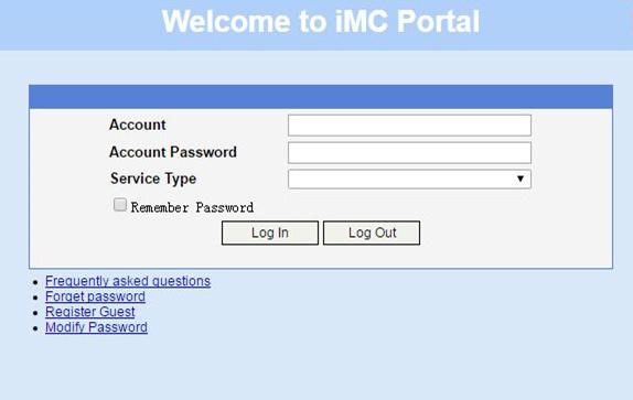
# Display IPoE session information to verify that the host has passed Web authentication and come online.
[Device] display ip subscriber session verbose
Basic:
Description : -
Username : user1
Domain : dm2
VPN instance : N/A
IP address : 192.168.0.2
User address type : N/A
MAC address : 0015-e947-f4d4
Service-VLAN/Customer-VLAN : -/-
Access interface : GE3/1/2
User ID : 0x3808001c
VPI/VCI(for ATM) : -/-
VSI Index : -
VSI link ID : -
VXLAN ID : -
DNS servers : 8.8.8.8
IPv6 DNS servers : N/A
DHCP lease : 86400 sec
DHCP remain lease : 86380 sec
Access time : Aug 2 16:52:28 2016
Online time(hh:mm:ss) : 00:00:20
Service node : Slot 3 CPU 0
Authentication type : Web
IPv4 access type : DHCP
IPv4 detect state : Detecting
State : Online
AAA:
ITA policy name : N/A
IP pool : pool1
IPv6 pool : N/A
Primary DNS server : N/A
Secondary DNS server : N/A
Primary IPv6 DNS server : N/A
Secondary IPv6 DNS server : N/A
Session idle cut : N/A
Session duration : N/A, remaining: N/A
Traffic quota : N/A
Traffic remained : N/A
Acct start-fail action : Online
Acct update-fail action : Online
Acct quota-out action : Offline
Dual-stack accounting mode : Merge
Max IPv4 multicast addresses: 4
IPv4 multicast address list : N/A
Max IPv6 multicast addresses: 4
IPv6 multicast address list : N/A
Accounting start time : Aug 2 16:52:28 2016
Subscriber ID : -
QoS:
User profile : N/A
Session group profile : N/A
User group ACL : N/A
Inbound CAR : N/A
Outbound CAR : N/A
Inbound user priority : N/A
Outbound user priority : N/A
Flow statistic:
Uplink packets/bytes : 0/0
Downlink packets/bytes : 0/0
IPv6 uplink packets/bytes : 0/0
IPv6 downlink packets/bytes : 0/0
# Click Log Out on the page as shown in Figure 121.
# Verify that the user returns to the preauthentication status.
[Device] display ip subscriber session verbose
Basic:
Description : -
Username : 0015e947f4d4
Domain : dm1
VPN instance : N/A
IP address : 192.168.0.2
User address type : N/A
MAC address : 0015-e947-f4d4
Service-VLAN/Customer-VLAN : -/-
Access interface : GE3/1/2
User ID : 0x3808001c
VPI/VCI(for ATM) : -/-
VSI Index : -
VSI link ID : -
VXLAN ID : -
DNS servers : 8.8.8.8
IPv6 DNS servers : N/A
DHCP lease : 86400 sec
DHCP remain lease : N/A
Access time : Aug 2 16:52:59 2016
Online time(hh:mm:ss) : 00:00:20
Service node : Slot 3 CPU 0
Authentication type : Web pre-auth
IPv4 access type : DHCP
IPv4 detect state : Detecting
State : Online
AAA:
ITA policy name : N/A
IP pool : pool1
IPv6 pool : N/A
Primary DNS server : N/A
Secondary DNS server : N/A
Primary IPv6 DNS server : N/A
Secondary IPv6 DNS server : N/A
Session idle cut : N/A
Session duration : N/A, remaining: N/A
Traffic quota : N/A
Traffic remained : N/A
Acct start-fail action : Online
Acct update-fail action : Online
Acct quota-out action : Offline
Dual-stack accounting mode : Merge
Max IPv4 multicast addresses: 4
IPv4 multicast address list : N/A
Max IPv6 multicast addresses: 4
IPv6 multicast address list : N/A
Accounting start time : Aug 2 16:52:59 2016
Redirect URL : http://4.4.4.5:8080/portal/
Subscriber ID : -
QoS:
User profile : N/A
Session group profile : N/A
User group ACL : web (active)
Inbound CAR : N/A
Outbound CAR : N/A
Inbound user priority : N/A
Outbound user priority : N/A
Flow statistic:
Uplink packets/bytes : 0/0
Downlink packets/bytes : 0/0
IPv6 uplink packets/bytes : 0/0
IPv6 downlink packets/bytes : 0/0
# Open the browser, and enter any address in the address bar to access http://63.1.1.240/. Display session information. The output shows that the user has come online through Web authentication.
[Device] display ip subscriber session verbose
Basic:
Description : -
Username : web
Domain : dm2
VPN instance : N/A
IP address : 192.168.0.2
User address type : N/A
MAC address : 0015-e947-f4d4
Service-VLAN/Customer-VLAN : -/-
Access interface : GE3/1/2
User ID : 0x3808001c
VPI/VCI(for ATM) : -/-
VSI Index : -
VSI link ID : -
VXLAN ID : -
DNS servers : 8.8.8.8
IPv6 DNS servers : N/A
DHCP lease : 86400 sec
DHCP remain lease : N/A
Access time : Aug 2 16:53:28 2016
Online time(hh:mm:ss) : 00:00:20
Service node : Slot 3 CPU 0
Authentication type : Web mac-auth
IPv4 access type : DHCP
IPv4 detect state : Detecting
State : Online
AAA:
ITA policy name : N/A
IP pool : pool1
IPv6 pool : N/A
Primary DNS server : N/A
Secondary DNS server : N/A
Primary IPv6 DNS server : N/A
Secondary IPv6 DNS server : N/A
Session idle cut : N/A
Session duration : N/A, remaining: N/A
Traffic quota : N/A
Traffic remained : N/A
Acct start-fail action : Online
Acct update-fail action : Online
Acct quota-out action : Offline
Dual-stack accounting mode : Merge
Max IPv4 multicast addresses: 4
IPv4 multicast address list : N/A
Max IPv6 multicast addresses: 4
IPv6 multicast address list : N/A
Accounting start time : Aug 2 16:53:28 2016
Subscriber ID : -
QoS:
User profile : N/A
Session group profile : N/A
User group ACL : N/A
Inbound CAR : N/A
Outbound CAR : N/A
Inbound user priority : N/A
Outbound user priority : N/A
Flow statistic:
Uplink packets/bytes : 0/0
Downlink packets/bytes : 0/0
IPv6 uplink packets/bytes : 0/0
IPv6 downlink packets/bytes : 0/0
Example: Configuring IPoE Layer 3 transparent MAC authentication
Network configuration
As shown in Figure 122, the host accesses the BRAS as a DHCP client though a Layer 3 network. The BRAS also acts as the DHCP server. A server installed with H3C IMC acts as the portal authentication server and the portal Web server. A RADIUS server that supports MAC binding acts as the authentication, authorization, and accounting server and performs MAC binding. The FTP server is an internal network server.
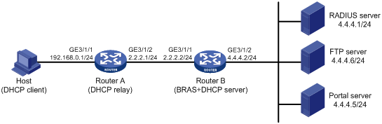
Procedure
1. Configure the DHCP relay agent:
# Enable DHCP.
<RouterA> system-view
[RouterA] dhcp enable
# Enable the DHCP relay agent to record client information in relay entries.
[RouterA] dhcp relay client-information record
# Disable the DHCP relay agent from periodically refreshing dynamic relay entries.
[RouterA] undo dhcp relay client-information refresh enable
# Enable DHCP server proxy on the DHCP relay agent and specify DHCP server address 2.2.2.2 on GigabitEthernet 3/1/1.
[RouterA] interface gigabitethernet 3/1/1
[RouterA–GigabitEthernet3/1/1] dhcp select relay proxy
[RouterA–GigabitEthernet3/1/1] dhcp relay server-address 2.2.2.2
[RouterA–GigabitEthernet3/1/1] quit
# Configure the default route from the DHCP relay agent to the BRAS.
[RouterA] ip route-static 0.0.0.0 24 2.2.2.2
2. Configure Router B:
a. Configure IP addresses for interfaces. (Details not shown.)
b. Configure the DHCP server:
# Enable DHCP.
<RouterB> system-view
[RouterB] dhcp enable
# Create an IP address pool named pool1 and enter its view.
[RouterB] dhcp server ip-pool pool1
# Specify primary subnet 192.168.0.0/24 for dynamic allocation in DHCP address pool pool1.
[RouterB-dhcp-pool-pool1] network 192.168.0.0 24
# Specify gateway address 192.168.0.1 in DHCP address pool pool1.
[RouterB-dhcp-pool-pool1] gateway-list 192.168.0.1
# Specify DNS server address 8.8.8.8 in DHCP address pool pool1.
[RouterB-dhcp-pool-pool1] dns-list 8.8.8.8
# Exclude IP address 192.168.0.1 from dynamic allocation in DHCP address pool pool1.
[RouterB-dhcp-pool-pool1] forbidden-ip 192.168.0.1
[RouterB-dhcp-pool-pool1] quit
# Configure a static route to the DHCP relay agent.
[RouterB] ip route-static 192.168.0.0 24 2.2.2.1
c. Configure the IP address of the portal authentication server newpt as 4.4.4.5 and the plaintext key 123456.
[RouterB] portal server newpt
[RouterB-portal-server-newpt] ip 4.4.4.5 key simple 123456
[RouterB-portal-server-newpt] quit
d. Specify 11111 as the HTTPS redirect listening port number.
[RouterB] http-redirect https-port 11111
e. Create a local user group named web.
[RouterB] user-group web
New user group added.
[Device-ugroup-web] quit
f. Configure ACLs for preauthentication:
# Create an IPv4 advanced ACL named web_permit. Configure a rule to permit all packets destined for the portal server from users in user group web.
[RouterB] acl advanced name web_permit
[RouterB-acl-ipv4-adv-web_permit] rule 0 permit ip destination 4.4.4.5 0 user-group web
[RouterB-acl-ipv4-adv-web_permit] quit
# Create an IPv4 advanced ACL named neiwang. Configure a rule to permit all packets destined for the internal network server from users in user group web.
[RouterB] acl advanced name neiwang
[RouterB-acl-ipv4-adv-neiwang] rule 0 permit ip destination 4.4.4.6 0 user-group web
[RouterB-acl-ipv4-adv-neiwang] quit
# Create an IPv4 advanced ACL named web_http. Configure a rule to permit TCP packets with the destination port 80 (HTTP packets) from users in user group web.
[RouterB] acl advanced name web_http
[RouterB-acl-ipv4-adv-web_http] rule 0 permit tcp destination-port eq www user-group web
[RouterB-acl-ipv4-adv-web_http] quit
# Create an IPv4 advanced ACL named web_https, and configure a rule to permit TCP packets with the destination port 443 (HTTPS packets) from users in user group web.
[RouterB] acl advanced name web_https
[RouterB-acl-ipv4-adv-web_https] rule 0 permit tcp destination-port eq 443 user-group web
[RouterB-acl-ipv4-adv-web_https] quit
# Create an IPv4 advanced ACL named ip, and configure a rule to permit IP packets from users in user group web.
[RouterB] acl advanced name ip
[RouterB-acl-ipv4-adv-ip] rule 0 permit ip user-group web
[RouterB-acl-ipv4-adv-ip] quit
# Create an IPv4 advanced ACL named neiwang_out, and configure a rule to permit IP packets from the internal network server in user group web.
[RouterB] acl advanced name neiwang_out
[RouterB-acl-ipv4-adv-neiwang_out] rule 0 permit ip source 4.4.4.6 0 user-group web
[RouterB-acl-ipv4-adv-neiwang_out] quit
# Create an IPv4 advanced ACL named web_out, and configure a rule to permit IP packets from the portal server in user group web.
[RouterB] acl advanced name web_out
[RouterB-acl-ipv4-adv-web_out] rule 0 permit ip source 4.4.4.5 0 user-group web
[RouterB-acl-ipv4-adv-web_out] quit
g. Configure QoS traffic classes for preauthentication users:
# Create the traffic class web_permit and specify ACL web_permit as the match criterion.
[RouterB] traffic classifier web_permit operator and
[RouterB-classifier-web_permit] if-match acl name web_permit
[RouterB-classifier-web_permit] quit
# Create the traffic class neiwang and specify ACL neiwang as the match criterion.
[RouterB] traffic classifier neiwang operator and
[RouterB-classifier-neiwang] if-match acl name neiwang
[RouterB-classifier-neiwang] quit
# Create the traffic class web_http and specify ACL web_http as the match criterion.
[RouterB] traffic classifier web_http operator and
[RouterB-classifier-web_http] if-match acl name web_http
[RouterB-classifier-web_http] quit
# Create the traffic class web_https and specify ACL web_https as the match criterion.
[RouterB] traffic classifier web_https operator and
[RouterB-classifier-web_https] if-match acl name web_https
[RouterB-classifier-web_https] quit
# Create the traffic class ip_cpu and specify ACL ip as the match criterion.
[Device] traffic classifier ip_cpu operator and
[Device-classifier-ip_cpu] if-match acl name ip
[Device-classifier-ip_cpu] quit
# Create the traffic class ip_deny and specify ACL ip as the match criterion.
[Device] traffic classifier ip_deny operator and
[Device-classifier-ip_deny] if-match acl name ip
[Device-classifier-ip_deny] quit
# Create the traffic class neiwang_out and specify ACL neiwang_out as the match criterion.
[RouterB] traffic classifier neiwang_out operator and
[RouterB-classifier-neiwang_out] if-match acl name neiwang_out
[RouterB-classifier-neiwang_out] quit
# Create the traffic class web_out and specify ACL web_out as the match criterion.
[RouterB] traffic classifier web_out operator and
[RouterB-classifier-web_out] if-match acl name web_out
[RouterB-classifier-web_out] quit
h. Configure QoS traffic behaviors:
# Configure the traffic behavior web_permit to permit traffic to pass through without rate limiting or accounting.
[RouterB] traffic behavior web_permit
[RouterB-behavior-web_permit] filter permit
[RouterB-behavior-web_permit] free account
[RouterB-behavior-web_permit] quit
# Configure the traffic behavior neiwang to permit traffic to pass through.
[RouterB] traffic behavior neiwang
[RouterB-behavior-neiwang] filter permit
[RouterB-behavior-neiwang] quit
# Configure the traffic behavior web_http to redirect HTTP packets to the CPU.
[RouterB] traffic behavior web_http
[RouterB-behavior-web_http] redirect http-to-cpu
[RouterB-behavior-web_http] quit
# Configure the traffic behavior web_https to redirect HTTPS packets to the CPU.
[RouterB] traffic behavior web_https
[RouterB-behavior-web_https] redirect https-to-cpu
[RouterB-behavior-web_https] quit
# Configure the traffic behavior web_cpu to redirect traffic to the CPU.
[Device] traffic behavior web_cpu
[Device-behavior-web_cpu] redirect cpu
[Device-behavior-web_cpu] quit
# Configure the traffic behavior web_deny to deny traffic.
[RouterB] traffic behavior web_deny
[RouterB-behavior-web_deny] filter deny
[RouterB-behavior-web_deny] free account
[RouterB-behavior-web_deny] quit
# Configure the traffic behavior neiwang_out to permit traffic to pass through.
[RouterB] traffic behavior neiwang_out
[RouterB-behavior-neiwang_out] filter permit
[RouterB-behavior-neiwang_out] quit
# Configure the traffic behavior web_out to permit traffic without rate limiting or traffic accounting.
[RouterB] traffic behavior web_out
[RouterB-behavior-web_out] filter permit
[RouterB-behavior-web_out] free account
[RouterB-behavior-web_out] quit
i. Configure the QoS policies:
# Create a QoS policy named web.
[RouterB] qos policy web
# Associate the traffic class web_permit with the traffic behavior web_permit.
[RouterB-qospolicy-web] classifier web_permit behavior web_permit
# Associate the traffic class neiwang with the traffic behavior neiwang.
[RouterB-qospolicy-web] classifier neiwang behavior neiwang
# Associate the traffic class web_http with the traffic behavior web_http.
[RouterB-qospolicy-web] classifier web_http behavior web_http
# Associate the traffic class web_https with the traffic behavior web_https.
[RouterB-qospolicy-web] classifier web_https behavior web_https
# Associate the traffic class ip_cpu with the traffic behavior web_cpu.
[RouterB-qospolicy-web] classifier ip_cpu behavior web_cpu
# Associate the traffic class ip_deny with the traffic behavior web_deny.
[RouterB-qospolicy-web] classifier ip_deny behavior web_deny
[RouterB-qospolicy-web] quit
# Configure a QoS policy named out.
[RouterB] qos policy out
# Associate the traffic class web_out with the traffic behavior web_out. Associate the traffic class neiwang_out with the traffic behavior neiwang_out. Associate the traffic class ip_deny with the traffic behavior web_deny.
[RouterB-qospolicy-out] classifier web_out behavior web_out
[RouterB-qospolicy-out] classifier neiwang_out behavior neiwang_out
[RouterB-qospolicy-out] classifier ip_deny behavior web_deny
[RouterB-qospolicy-out] quit
j. Apply the QoS policies:
# Apply the QoS Policy web to the inbound traffic globally.
[RouterB] qos apply policy web global inbound
# Apply the QoS Policy out to the outbound traffic globally.
[RouterB] qos apply policy out global outbound
k. Configure a RADIUS scheme:
# Create a RADIUS scheme named rs1 and enter its view.
[RouterB] radius scheme rs1
# Configure primary servers and keys for authentication and accounting.
[RouterB-radius-rs1] primary authentication 4.4.4.1
[RouterB-radius-rs1] primary accounting 4.4.4.1
[RouterB-radius-rs1] key authentication simple radius
[RouterB-radius-rs1] key accounting simple radius
# Exclude the ISP name from the username sent to the RADIUS server.
[RouterB-radius-rs1] user-name-format without-domain
[RouterB-radius-rs1] quit
l. Configure the preauthentication ISP domain and Web authentication ISP domain:
# Configure the ISP domain dm1 for IPoE user preauthentication.
[RouterB] domain name dm1
[RouterB-isp-dm1] authentication ipoe none
[RouterB-isp-dm1] authorization ipoe none
[RouterB-isp-dm1] accounting ipoe none
# Configure the authorized IP address pool and user group in ISP domain dm1.
[RouterB-isp-dm1] authorization-attribute user-group web
[RouterB-isp-dm1] authorization-attribute ip-pool pool1
# Configure the Web authentication page URL in ISP domain dm1.
[RouterB-isp-dm1] web-server url http://4.4.4.5:8080/portal/
[RouterB-isp-dm1] quit
# Configure the ISP domain dm2 for IPoE user Web authentication.
[RouterB] domain name dm2
[RouterB-isp-dm2] authentication ipoe radius-scheme rs1
[RouterB-isp-dm2] authorization ipoe radius-scheme rs1
[RouterB-isp-dm2] accounting ipoe radius-scheme rs1
[RouterB-isp-dm2] quit
m. Configure basic IPoE transparent authentication:
# Enable IPoE and configure Layer 3 access mode on GigabitEthernet 3/1/1.
[RouterB] interface gigabitethernet 3/1/1
[RouterB–GigabitEthernet3/1/1] ip subscriber routed enable
# Configure Web MAC authentication for IPoE users on GigabitEthernet 3/1/1.
[RouterB–GigabitEthernet3/1/1] ip subscriber authentication-method web mac-auth
The operation may cut all users on this interface. Continue?[Y/N]:y
# Configure the ISP domain dm1 for preauthentication and the ISP domain dm2 for preauthentication on GigabitEthernet 3/1/1.
[RouterB–GigabitEthernet3/1/1] ip subscriber pre-auth domain dm1
[RouterB–GigabitEthernet3/1/1] ip subscriber web-auth domain dm2
# Configure online detection on GigabitEthernet 3/1/1. The maximum number of detection attempts is 5, the detection timer is 120 seconds, and the detection packet type is ICMP.
The detection packet type is ARP by default. To use Layer 3 transparent authentication, you must set the detection packet type to ICMP or disable online detection.
[RouterB–GigabitEthernet3/1/1] ip subscriber user-detect ip icmp retry 5 interval 120
[RouterB–GigabitEthernet3/1/1] quit
n. (Optional.) Allow abnormally logged out IPoE DHCP users to come online again:
|
|
NOTE: · To allow abnormally logged out DHCP users to come online again through packet initiation in the network, configure this feature. · This section describes only the key configuration for allowing abnormally logged out users to come online again. For how this feature works and the configuration restrictions and guidelines for this feature, see "Allowing abnormally logged out DHCP users to come online again through packet initiation." |
# Enable DHCP packet initiation.
[Device] interface gigabitethernet 3/1/1
[Device–GigabitEthernet3/1/1] ip subscriber initiator dhcp enable
# Enable ARP packet initiation.
[Device–GigabitEthernet3/1/1] ip subscriber initiator arp enable
# Enable unclassified-IP packet initiation.
[Device–GigabitEthernet3/1/1] ip subscriber initiator unclassified-ip enable matching-user
[Device–GigabitEthernet3/1/1] quit
o. (Optional.) Configure roaming for IPoE DHCP users:
|
|
NOTE: · Configure this feature in a network where users need roaming. · This section describes only the key configuration for DHCP user roaming. For how this feature works and the configuration restrictions and guidelines for this feature, see "Enabling roaming for IPoE individual users." |
# Enable DHCP packet initiation.
[Device] interface gigabitethernet 3/1/1
[Device–GigabitEthernet3/1/1] ip subscriber initiator dhcp enable
# Enable ARP packet initiation.
[Device–GigabitEthernet3/1/1] ip subscriber initiator arp enable
# Enable unclassified-IP packet initiation.
[Device–GigabitEthernet3/1/1] ip subscriber initiator unclassified-ip enable matching-user
# Enable roaming for IPoE individual users.
[Device–GigabitEthernet3/1/1] ip subscriber roaming enable
# Configure DHCP on GigabitEthernet 3/1/1 to release the online lease for a MAC address of a user and then allocate an IP address to the user after GigabitEthernet 3/1/1 receives a DHCP-DISCOVER packet from an online user whose physical location changes and MAC address does not change.
[Device–GigabitEthernet3/1/1] dhcp session-mismatch action fast-renew
[Device–GigabitEthernet3/1/1] quit
3. Configure the RADIUS server.
For more information about configuring AAA and MAC binding on the RADIUS server, see the configuration guide for the RADIUS server.
4. Configure the portal server:
a. Configure the portal homepage:
i Select User Access Policy > Portal Service > Server from the navigation tree to open the portal server configuration page, as shown in Figure 123.
ii Click OK.
Figure 123 Portal server configuration page
a. Configure portal authentication source IP address range:
i Select User Access Policy > Portal Service > IP Group from the navigation tree to open the portal IP address group configuration page.
ii Click Add to open the page as shown in Figure 124.
iii Enter the IP group name IPoE_Web_User.
iv Enter the start IP address (192.168.0.1) and end IP address (192.168.0.255) of the IP group. Make sure the host IP address is in the IP group.
v Click OK.
Figure 124 Adding an IP address group
a. Add a portal device:
i Select User Access Policy > Portal Service > Device from the navigation tree to open the portal device configuration page.
ii Click Add to open the page as shown in Figure 125.
iii Enter the device name NAS.
iv Enter the IP address of the portal packets' outgoing interface GigabitEthernet 3/1/2 (4.4.4.2).
v Enter the key 123456.
vi Select Directly Connect for access method.
vii Click OK.
Figure 125 Adding a portal device
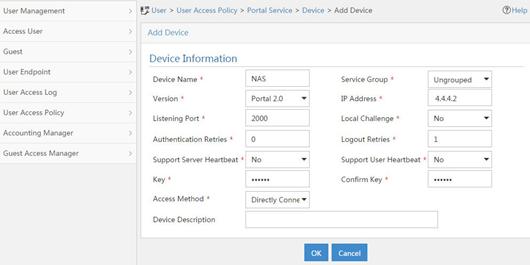
a. Associate the portal device with the IP address group:
i Click the icon in the Port Group Information Management column of device NAS to open the port group configuration page, as shown in Figure 126.
ii Click Add to open the page as shown in Figure 127.
iii Enter the port group name group.
iv Select the configured IP address group IPoE_Web_User. Make sure the IP address used by the user to access the network is within this IP address group.
v Click OK.
Figure 127 Port group configuration
Verifying the configuration
# Display IPoE session information to verify that the host has passed preauthentication.
[RouterB] display ip subscriber session verbose
Basic:
Description : -
Username : 0015e947f4d4
Domain : dm1
VPN instance : N/A
IP address : 192.168.0.2
User address type : N/A
MAC address : 0015-e947-f4d4
Service-VLAN/Customer-VLAN : -/-
Access interface : GE3/1/1
User ID : 0x3808001c
VPI/VCI(for ATM) : -/-
VSI Index : -
VSI link ID : -
VXLAN ID : -
DNS servers : 8.8.8.8
IPv6 DNS servers : N/A
DHCP lease : 86400 sec
DHCP remain lease : 86380 sec
Access time : Aug 2 16:51:28 2016
Online time(hh:mm:ss) : 00:00:20
Service node : Slot 3 CPU 0
Authentication type : Web pre-auth
IPv4 access type : DHCP
IPv4 detect state : Detecting
State : Online
AAA:
ITA policy name : N/A
IP pool : pool1
IPv6 pool : N/A
Primary DNS server : N/A
Secondary DNS server : N/A
Primary IPv6 DNS server : N/A
Secondary IPv6 DNS server : N/A
Session idle cut : N/A
Session duration : N/A, remaining: N/A
Traffic quota : N/A
Traffic remained : N/A
Acct start-fail action : Online
Acct update-fail action : Online
Acct quota-out action : Offline
Dual-stack accounting mode : Merge
Max IPv4 multicast addresses: 4
IPv4 multicast address list : N/A
Max IPv6 multicast addresses: 4
IPv6 multicast address list : N/A
Accounting start time : Aug 2 16:51:28 2016
Redirect URL : http://4.4.4.5:8080/portal/
Subscriber ID : -
QoS:
User profile : N/A
Session group profile : N/A
User group ACL : web (active)
Inbound CAR : N/A
Outbound CAR : N/A
Inbound user priority : N/A
Outbound user priority : N/A
Flow statistic:
Uplink packets/bytes : 0/0
Downlink packets/bytes : 0/0
IPv6 uplink packets/bytes : 0/0
IPv6 downlink packets/bytes : 0/0
As shown in Figure 128, the Web login page opens after preauthentication. Enter the username and password on the page.
# Display IPoE session information to verify that the host has passed Web authentication and come online.
[RouterB] display ip subscriber session verbose
Basic:
Description : -
Username : user1
Domain : dm2
VPN instance : N/A
IP address : 192.168.0.2
User address type : N/A
MAC address : 0015-e947-f4d4
Service-VLAN/Customer-VLAN : -/-
Access interface : GE3/1/1
User ID : 0x3808001c
VPI/VCI(for ATM) : -/-
VSI Index : -
VSI link ID : -
VXLAN ID : -
DNS servers : 8.8.8.8
IPv6 DNS servers : N/A
DHCP lease : 86400 sec
DHCP remain lease : 86380 sec
Access time : Aug 2 16:52:28 2016
Online time(hh:mm:ss) : 00:00:20
Service node : Slot 3 CPU 0
Authentication type : Web
IPv4 access type : DHCP
IPv4 detect state : Detecting
State : Online
AAA:
ITA policy name : N/A
IP pool : pool1
IPv6 pool : N/A
Primary DNS server : N/A
Secondary DNS server : N/A
Primary IPv6 DNS server : N/A
Secondary IPv6 DNS server : N/A
Session idle cut : N/A
Session duration : N/A, remaining: N/A
Traffic quota : N/A
Traffic remained : N/A
Acct start-fail action : Online
Acct update-fail action : Online
Acct quota-out action : Offline
Dual-stack accounting mode : Merge
Max IPv4 multicast addresses: 4
IPv4 multicast address list : N/A
Max IPv6 multicast addresses: 4
IPv6 multicast address list : N/A
Accounting start time : Aug 2 16:52:28 2016
Subscriber ID : -
QoS:
User profile : N/A
Session group profile : N/A
User group ACL : N/A
Inbound CAR : N/A
Outbound CAR : N/A
Inbound user priority : N/A
Outbound user priority : N/A
Flow statistic:
Uplink packets/bytes : 0/0
Downlink packets/bytes : 0/0
IPv6 uplink packets/bytes : 0/0
IPv6 downlink packets/bytes : 0/0
# Click Log Out on the page as shown in Figure 128.
# Verify that the user returns to the preauthentication status.
[RouterB] display ip subscriber session verbose
Basic:
Description : -
Username : 0015e947f4d4
Domain : dm1
VPN instance : N/A
IP address : 192.168.0.2
User address type : N/A
MAC address : 0015-e947-f4d4
Service-VLAN/Customer-VLAN : -/-
Access interface : GE3/1/1
User ID : 0x3808001c
VPI/VCI(for ATM) : -/-
VSI Index : -
VSI link ID : -
VXLAN ID : -
DNS servers : 8.8.8.8
IPv6 DNS servers : N/A
DHCP lease : 86400 sec
DHCP remain lease : N/A
Access time : Aug 2 16:52:59 2016
Online time(hh:mm:ss) : 00:00:20
Service node : Slot 3 CPU 0
Authentication type : Web pre-auth
IPv4 access type : DHCP
IPv4 detect state : Detecting
State : Online
AAA:
ITA policy name : N/A
IP pool : pool1
IPv6 pool : N/A
Primary DNS server : N/A
Secondary DNS server : N/A
Primary IPv6 DNS server : N/A
Secondary IPv6 DNS server : N/A
Session idle cut : N/A
Session duration : N/A, remaining: N/A
Traffic quota : N/A
Traffic remained : N/A
Acct start-fail action : Online
Acct update-fail action : Online
Acct quota-out action : Offline
Dual-stack accounting mode : Merge
Max IPv4 multicast addresses: 4
IPv4 multicast address list : N/A
Max IPv6 multicast addresses: 4
IPv6 multicast address list : N/A
Accounting start time : Aug 2 16:52:59 2016
Redirect URL : http://4.4.4.5:8080/portal/
Subscriber ID : -
QoS:
User profile : N/A
Session group profile : N/A
User group ACL : web (active)
Inbound CAR : N/A
Outbound CAR : N/A
Inbound user priority : N/A
Outbound user priority : N/A
Flow statistic:
Uplink packets/bytes : 0/0
Downlink packets/bytes : 0/0
IPv6 uplink packets/bytes : 0/0
IPv6 downlink packets/bytes : 0/0
# Open the browser, and enter any address in the address bar to access http://63.1.1.240/. Display session information. The output shows that the user has come online through Web authentication.
[RouterB] display ip subscriber session verbose
Basic:
Description : -
Username : web
Domain : dm2
VPN instance : N/A
IP address : 192.168.0.2
User address type : N/A
MAC address : 0015-e947-f4d4
Service-VLAN/Customer-VLAN : -/-
Access interface : GE3/1/1
User ID : 0x3808001c
VPI/VCI(for ATM) : -/-
VSI Index : -
VSI link ID : -
VXLAN ID : -
DNS servers : 8.8.8.8
IPv6 DNS servers : N/A
DHCP lease : 86400 sec
DHCP remain lease : N/A
Access time : Aug 2 16:53:28 2016
Online time(hh:mm:ss) : 00:00:20
Service node : Slot 3 CPU 0
Authentication type : Web mac-auth
IPv4 access type : DHCP
IPv4 detect state : Detecting
State : Online
AAA:
ITA policy name : N/A
IP pool : pool1
IPv6 pool : N/A
Primary DNS server : N/A
Secondary DNS server : N/A
Primary IPv6 DNS server : N/A
Secondary IPv6 DNS server : N/A
Session idle cut : N/A
Session duration : N/A, remaining: N/A
Traffic quota : N/A
Traffic remained : N/A
Acct start-fail action : Online
Acct update-fail action : Online
Acct quota-out action : Offline
Dual-stack accounting mode : Merge
Max IPv4 multicast addresses: 4
IPv4 multicast address list : N/A
Max IPv6 multicast addresses: 4
IPv6 multicast address list : N/A
Accounting start time : Aug 2 16:53:28 2016
Subscriber ID : -
QoS:
User profile : N/A
Session group profile : N/A
User group ACL : N/A
Inbound CAR : N/A
Outbound CAR : N/A
Inbound user priority : N/A
Outbound user priority : N/A
Flow statistic:
Uplink packets/bytes : 0/0
Downlink packets/bytes : 0/0
IPv6 uplink packets/bytes : 0/0
IPv6 downlink packets/bytes : 0/0
Example: Configuring IPoE transparent MAC authentication for dual-stack users
Network configuration
As shown in Figure 129, the host accesses the BRAS as a DHCP client though a Layer 2 device. It obtains configuration information from the DHCP server through the BRAS. The BRAS performs AAA for the host through the RADIUS server. A server installed with H3C IMC acts as the portal authentication server and the portal Web server. A RADIUS server that supports MAC binding acts as the authentication, authorization, and accounting server and performs MAC binding. The FTP server is an internal network server. Limit the access rate to 5 Mbps for the user after passing Web authentication.
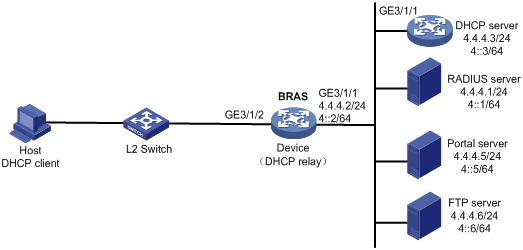
Procedure
1. Configure IP addresses and routes.
As shown in Figure 129, configure IP addresses for interfaces and make sure the BRAS and servers can reach each other at Layer 3. (Details not shown.)
2. Configure the DNS server.
Configure the DNS server properly, so that the server can parse the IPv4 URL or IPv6 URL corresponding to the Web authentication page http://www.h3c.web.com according to the first protocol stack that comes online of the IPoE dual-stack user. (Details not shown.)
3. Configure the DHCP servers:
a. Configure the DHCPv4 address pool:
# Enable DHCP.
<DHCP> system-view
[DHCP] dhcp enable
# Create a DHCPv4 address pool named pool1 and enter its view.
[DHCP] dhcp server ip-pool pool1
# Specify primary subnet 192.168.0.0/24 for dynamic allocation in DHCPv4 address pool pool1.
[DHCP-dhcp-pool-pool1] network 192.168.0.0 24
# Specify gateway address 192.168.0.1 in DHCPv4 address pool pool1.
[DHCP-dhcp-pool-pool1] gateway-list 192.168.0.1
# Exclude IP address 192.168.0.1 from dynamic allocation in DHCPv4 address pool pool1.
[DHCP-dhcp-pool-pool1] forbidden-ip 192.168.0.1
[DHCP-dhcp-pool-pool1] quit
# Configure a static route to specify the next hop of DHCPv4 replies destined to network segment 192.168.0.0 as the IP address of the interface connected to the DHCPv4 client, 4.4.4.2.
[DHCP] ip route-static 192.168.0.0 24 4.4.4.2
b. Configure the DHCPv6 address pool:
# Create a DHCPv6 address pool named pool2 and enter its view.
[DHCP] ipv6 dhcp pool pool2
# Specify primary subnet 192::0/64 for dynamic allocation in DHCPv6 address pool pool2.
[DHCP-dhcp6-pool-pool2] network 192::0/64
[DHCP-dhcp6-pool-pool2] quit
# Exclude IP address 192::1 from dynamic allocation in DHCPv6 address pool pool2.
[DHCP] ipv6 dhcp server forbidden-address 192::1
# Enable the DHCPv6 server on GigabitEthernet 3/1/1.
[DHCP] interface gigabitethernet 3/1/1
[DHCP-GigabitEthernet3/1/1] ipv6 dhcp select server
[DHCP-GigabitEthernet3/1/1] quit
# Configure a static route to specify the next hop of DHCPv6 replies destined to network segment 192::0 as the IP address of the interface connected to the DHCPv6 client, 4::2.
[DHCP] ipv6 route-static 192::0 64 4::2
4. Configure the BRAS:
a. Configure the DHCP relay agent:
# Enable DHCP.
<Device> system-view
[Device] dhcp enable
# Enable the DHCP relay agent to record client information in relay entries.
[Device] dhcp relay client-information record
# Disable the DHCP relay agent from periodically refreshing dynamic relay entries.
[Device] undo dhcp relay client-information refresh enable
# Create an IP address pool named pool1 for the DHCP relay agent.
[Device] dhcp server ip-pool pool1
# Specify gateway address 192.168.0.1 in DHCP address pool pool1.
[Device-dhcp-pool-pool1] gateway-list 192.168.0.1 export-route
# Specify DHCP server 4.4.4.3 in DHCP address pool pool1.
[Device-dhcp-pool-pool1] remote-server 4.4.4.3
[Device-dhcp-pool-pool1] quit
# Create an IP address pool named pool2 for the DHCP relay agent.
[Device] ipv6 dhcp pool pool2
# Specify gateway address 192::1 in DHCP address pool pool2.
[Device-dhcp6-pool-pool2] gateway-list 192::1
# Specify DHCP server 4::3 in DHCP address pool pool2.
[Device-dhcp6-pool-pool2] remote-server 4::3
[Device-dhcp6-pool-pool2] quit
# Enable DHCP server proxy on the DHCPv4 relay agent on GigabitEthernet 3/1/2.
[Device] interface gigabitethernet 3/1/2
[Device–GigabitEthernet3/1/2] dhcp select relay proxy
# Automatically generate a link-local address for GigabitEthernet 3/1/2.
[Device–GigabitEthernet3/1/2] ipv6 address auto link-local
# Enable the DHCPv6 relay agent on GigabitEthernet 3/1/2.
[Device–GigabitEthernet3/1/2] ipv6 dhcp select relay proxy
# Enable recording client information in DHCPv6 relay entries.
[Device–GigabitEthernet3/1/2] ipv6 dhcp relay client-information record
# Disable RA message suppression on GigabitEthernet 3/1/2.
[Device–GigabitEthernet3/1/2] undo ipv6 nd ra halt
# Set the managed address configuration flag (M) to 1 in RA advertisements to be sent. Then, the host uses a DHCPv6 server to obtain IPv6 addresses.
[Device–GigabitEthernet3/1/2] ipv6 nd autoconfig managed-address-flag
# Set the other stateful configuration flag (O) to 1 in RA advertisements to be sent. Then, the host uses a DHCPv6 server to obtain configuration information other than IPv6 addresses.
[Device–GigabitEthernet3/1/2] ipv6 nd autoconfig other-flag
# Disable GigabitEthernet 3/1/2 from advertising the specified prefix in RA messages, preventing the endpoint from obtaining a temporary IPv6 address. In an IPv6 network, an endpoint might use a temporary IPv6 address for IPoE Web authentication, which will cause authentication failure.
[Device–GigabitEthernet3/1/2] ipv6 nd ra prefix 192::/64 no-advertise
[Device–GigabitEthernet3/1/2] quit
b. Configure the portal servers:
# Configure the IP address of the IPv4 portal authentication server newpt1 as 4.4.4.5 and the plaintext key 123456.
[Device] portal server newpt1
[Device-portal-server-newpt1] ip 4.4.4.5 key simple 123456
[Device-portal-server-newpt1] quit
# Configure the IPv6 address of the IPv6 portal authentication server newpt2 as 4::5 and the plaintext key 123456.
[Device] portal server newpt2
[Device-portal-server-newpt2] ipv6 4::5 key simple 123456
[Device-portal-server-newpt2] quit
c. Specify 11111 as the HTTPS redirect listening port number.
[Device] http-redirect https-port 11111
d. Create a local user group named web.
[Device] user-group web
New user group added.
[Device-ugroup-web] quit
e. Configure ACLs for preauthentication:
# Create an IPv4 and IPv6 advanced ACL named web_permit separately. Configure a rule to permit all packets destined for the portal server from users in user group web.
[Device] acl advanced name web_permit
[Device-acl-ipv4-adv-web_permit] rule 0 permit ip destination 4.4.4.5 0 user-group web
[Device-acl-ipv4-adv-web_permit] quit
[Device] acl ipv6 advanced name web_permit
[Device-acl-ipv6-adv-web_permit] rule 0 permit ipv6 destination 4::5 128 user-group web
[Device-acl-ipv6-adv-web_permit] quit
# Create an IPv4 and IPv6 advanced ACL named neiwang separately. Configure a rule to permit all packets destined for the internal network server from users in user group web.
[Device] acl advanced name neiwang
[Device-acl-ipv4-adv-neiwang] rule 0 permit ip destination 4.4.4.6 0 user-group web
[Device-acl-ipv4-adv-neiwang] quit
[Device] acl ipv6 advanced name neiwang
[Device-acl-ipv6-adv-neiwang] rule 0 permit ipv6 destination 4::6 128 user-group web
[Device-acl-ipv6-adv-neiwang] quit
# Create an IPv4 and IPv6 advanced ACL named web_http separately. Configure a rule to permit TCP packets with the destination port 80 (HTTP packets) from users in user group web.
[Device] acl advanced name web_http
[Device-acl-ipv4-adv-web_http] rule 0 permit tcp destination-port eq www user-group web
[Device-acl-ipv4-adv-web_http] quit
[Device] acl ipv6 advanced name web_http
[Device-acl-ipv6-adv-web_http] rule 0 permit tcp destination-port eq www user-group web
[Device-acl-ipv6-adv-web_http] quit
# Create an IPv4 and IPv6 advanced ACL named web_https separately, and configure a rule to permit TCP packets with the destination port 443 (HTTPS packets) from users in user group web.
[Device] acl advanced name web_https
[Device-acl-ipv4-adv-web_https] rule 0 permit tcp destination-port eq 443 user-group web
[Device-acl-ipv4-adv-web_https] quit
[Device] acl ipv6 advanced name web_https
[Device-acl-ipv6-adv-web_https] rule 0 permit tcp destination-port eq 443 user-group web
[Device-acl-ipv6-adv-web_https] quit
# Create an IPv4 and IPv6 advanced ACL named ip separately, and configure a rule to permit IP packets from users in user group web.
[Device] acl advanced name ip
[Device-acl-ipv4-adv-ip] rule 0 permit ip user-group web
[Device-acl-ipv4-adv-ip] quit
[Device] acl ipv6 advanced name ip
[Device-acl-ipv6-adv-ip] rule 0 permit ipv6 user-group web
[Device-acl-ipv6-adv-ip] quit
# Create an IPv4 and IPv6 advanced ACL named neiwang_out separately, and configure a rule to permit IP packets from the internal network server in user group web.
[Device] acl advanced name neiwang_out
[Device-acl-ipv4-adv-neiwang_out] rule 0 permit ip source 4.4.4.6 0 user-group web
[Device-acl-ipv4-adv-neiwang_out] quit
[Device] acl ipv6 advanced name neiwang_out
[Device-acl-ipv6-adv-neiwang_out] rule 0 permit ipv6 source 4::6 128 user-group web
[Device-acl-ipv6-adv-neiwang_out] quit
# Create an IPv4 and IPv6 advanced ACL named web_out separately, and configure a rule to permit IP packets from the portal server in user group web.
[Device] acl advanced name web_out
[Device-acl-ipv4-adv-web_out] rule 0 permit ip source 4.4.4.5 0 user-group web
[Device-acl-ipv4-adv-web_out] quit
[Device] acl ipv6 advanced name web_out
[Device-acl-ipv6-adv-web_out] rule 0 permit ipv6 source 4::5 128 user-group web
[Device-acl-ipv6-adv-web_out] quit
f. Configure QoS traffic classes for preauthentication users:
# Create the traffic class web_permit and specify ACL web_permit as the match criterion.
[Device] traffic classifier web_permit operator or
[Device-classifier-web_permit] if-match acl name web_permit
[Device-classifier-web_permit] if-match acl ipv6 name web_permit
[Device-classifier-web_permit] quit
# Create the traffic class neiwang and specify ACL neiwang as the match criterion.
[Device] traffic classifier neiwang operator or
[Device-classifier-neiwang] if-match acl name neiwang
[Device-classifier-neiwang] if-match acl ipv6 name neiwang
[Device-classifier-neiwang] quit
# Create the traffic class web_http and specify ACL web_http as the match criterion.
[Device] traffic classifier web_http operator or
[Device-classifier-web_http] if-match acl name web_http
[Device-classifier-web_http] if-match acl ipv6 name web_http
[Device-classifier-web_http] quit
# Create the traffic class web_https and specify ACL web_https as the match criterion.
[Device] traffic classifier web_https operator or
[Device-classifier-web_https] if-match acl name web_https
[Device-classifier-web_https] if-match acl ipv6 name web_https
[Device-classifier-web_https] quit
# Create the traffic class ip_cpu and specify ACL ip as the match criterion.
[Device] traffic classifier ip_cpu operator or
[Device-classifier-ip_cpu] if-match acl name ip
[Device-classifier-ip_cpu] if-match acl ipv6 name ip
[Device-classifier-ip_cpu] quit
# Create the traffic class ip_deny and specify ACL ip as the match criterion.
[Device] traffic classifier ip_deny operator or
[Device-classifier-ip_deny] if-match acl name ip
[Device-classifier-ip_deny] if-match acl ipv6 name ip
[Device-classifier-ip_deny] quit
# Create the traffic class neiwang_out and specify ACL neiwang_out as the match criterion.
[Device] traffic classifier neiwang_out operator or
[Device-classifier-neiwang_out] if-match acl name neiwang_out
[Device-classifier-neiwang_out] if-match acl ipv6 name neiwang_out
[Device-classifier-neiwang_out] quit
# Create the traffic class web_out and specify ACL web_out as the match criterion.
[Device] traffic classifier web_out operator or
[Device-classifier-web_out] if-match acl name web_out
[Device-classifier-web_out] if-match acl ipv6 name web_out
[Device-classifier-web_out] quit
g. Configure QoS traffic behaviors:
# Configure the traffic behavior web_permit to permit traffic to pass through without rate limiting or accounting.
[Device] traffic behavior web_permit
[Device-behavior-web_permit] filter permit
[Device-behavior-web_permit] free account
[Device-behavior-web_permit] quit
# Configure the traffic behavior neiwang to permit traffic to pass through.
[Device] traffic behavior neiwang
[Device-behavior-neiwang] filter permit
[Device-behavior-neiwang] quit
# Configure the traffic behavior web_http to redirect HTTP packets to the CPU.
[Device] traffic behavior web_http
[Device-behavior-web_http] redirect http-to-cpu
[Device-behavior-web_http] quit
# Configure the traffic behavior web_https to redirect HTTPS packets to the CPU.
[Device] traffic behavior web_https
[Device-behavior-web_https] redirect https-to-cpu
[Device-behavior-web_https] quit
# Configure the traffic behavior web_cpu to redirect IP packets to the CPU.
[Device] traffic behavior web_cpu
[Device-behavior-web_cpu] redirect cpu
[Device-behavior-web_cpu] quit
# Configure the traffic behavior web_deny to deny traffic.
[Device] traffic behavior web_deny
[Device-behavior-web_deny] filter deny
[Device-behavior-web_deny] free account
[Device-behavior-web_deny] quit
# Configure the traffic behavior neiwang_out to permit traffic to pass through.
[Device] traffic behavior neiwang_out
[Device-behavior-neiwang_out] filter permit
[Device-behavior-neiwang_out] quit
# Configure the traffic behavior web_out to permit traffic without rate limiting or traffic accounting.
[Device] traffic behavior web_out
[Device-behavior-web_out] filter permit
[Device-behavior-web_out] free account
[Device-behavior-web_out] quit
h. Configure the QoS policies:
# Create a QoS policy named web.
[Device] qos policy web
# Associate the traffic class web_permit with the traffic behavior web_permit.
[Device-qospolicy-web] classifier web_permit behavior web_permit
# Associate the traffic class neiwang with the traffic behavior neiwang.
[Device-qospolicy-web] classifier neiwang behavior neiwang
# Associate the traffic class web_http with the traffic behavior web_http.
[Device-qospolicy-web] classifier web_http behavior web_http
# Associate the traffic class web_https with the traffic behavior web_https.
[Device-qospolicy-web] classifier web_https behavior web_https
# Associate the traffic class ip_cpu with the traffic behavior web_cpu.
[Device-qospolicy-web] classifier ip_cpu behavior web_cpu
# Associate the traffic class ip_deny with the traffic behavior web_deny.
[Device-qospolicy-web] classifier ip_deny behavior web_deny
[Device-qospolicy-web] quit
# Configure a QoS policy named out.
[Device] qos policy out
# Associate the traffic class web_out with the traffic behavior web_out. Associate the traffic class neiwang_out with the traffic behavior neiwang_out. Associate the traffic class web_deny with the traffic behavior web_deny.
[Device-qospolicy-out] classifier web_out behavior web_out
[Device-qospolicy-out] classifier neiwang_out behavior neiwang_out
[Device-qospolicy-out] classifier ip_deny behavior web_deny
[Device-qospolicy-out] quit
i. Apply the QoS policies:
# Apply the QoS Policy web to the inbound traffic globally.
[Device] qos apply policy web global inbound
# Apply the QoS Policy out to the outbound traffic globally.
[Device] qos apply policy out global outbound
j. Verify that the applied QoS policies take effect:
# Display the configuration and running status of the QoS policy applied to the inbound traffic globally.
[Device] display qos policy global slot 3 inbound
Direction: Inbound
Policy: web
Classifier: web_permit
Operator: OR
Rule(s) :
If-match acl name web_permit
If-match acl ipv6 name web_permit
Behavior: web_permit
Filter enable: Permit
Free account enable
Classifier: neiwang
Operator: OR
Rule(s) :
If-match acl name neiwang
If-match acl ipv6 name neiwang
Behavior: neiwang
Filter enable: Permit
Classifier: web_http
Operator: OR
Rule(s) :
If-match acl name web_http
If-match acl ipv6 name web_http
Behavior: web_http
Redirecting:
Redirect http to CPU
Classifier: web_https
Operator: OR
Rule(s) :
If-match acl name web_https
If-match acl ipv6 name web_https
Behavior: web_https
Redirecting:
Redirect https to CPU
Classifier: ip_cpu
Operator: OR
Rule(s) :
If-match acl name ip
If-match acl ipv6 name ip
Behavior: web_cpu
Redirecting:
Redirect to the CPU
Classifier: ip_deny
Operator: OR
Rule(s) :
If-match acl name ip
If-match acl ipv6 name ip
Behavior: web_deny
Filter enable: Deny
Free account enable
# Display the configuration and running status of the QoS policy applied to the outbound traffic globally.
[Device] display qos policy global slot 3 outbound
Direction: Outbound
Policy: out
Classifier: web_out
Operator: OR
Rule(s) :
If-match acl name web_out
If-match acl ipv6 name web_out
Behavior: web_out
Filter enable: Permit
Free account enable
Classifier: neiwang_out
Operator: OR
Rule(s) :
If-match acl name neiwang_out
If-match acl ipv6 name neiwang_out
Behavior: neiwang_out
Filter enable: Permit
Classifier: ip_deny
Operator: OR
Rule(s) :
If-match acl name ip
If-match acl ipv6 name ip
Behavior: web_deny
Filter enable: Deny
Free account enable
k. Configure a RADIUS scheme:
# Create a RADIUS scheme named rs1 and enter its view.
[Device] radius scheme rs1
# Configure primary servers and keys for authentication and accounting.
[Device-radius-rs1] primary authentication 4.4.4.1
[Device-radius-rs1] primary accounting 4.4.4.1
[Device-radius-rs1] key authentication simple radius
[Device-radius-rs1] key accounting simple radius
# Exclude the ISP name from the username sent to the RADIUS server.
[Device-radius-rs1] user-name-format without-domain
[Device-radius-rs1] quit
# Set the IP address of the RADIUS DAE client to 4.4.4.1, and set the shared key to radius for the RADIUS DAE client to exchange DAE packets.
[Device] radius dynamic-author server
[Device-radius-da-server] client ip 4.4.4.1 key simple radius
[Device-radius-da-server] quit
l. Configure the user profile:
# Create a user profile named car. Configure the user profile to perform traffic policing for incoming traffic of online users, with the CIR as 5210 kbps and CBS as 325625 bytes.
[Device] user-profile car
[Device-user-profile-car] qos car inbound any cir 5210 cbs 325625
[Device-user-profile-car] quit
m. Configure the preauthentication ISP domain and Web authentication ISP domain:
# Configure the ISP domain dm1 for IPoE user preauthentication.
[Device] domain name dm1
[Device-isp-dm1] authentication ipoe none
[Device-isp-dm1] authorization ipoe none
[Device-isp-dm1] accounting ipoe none
# Configure the authorized user group and IP address pools in preauthentication ISP domain dm1.
[Device-isp-dm1] authorization-attribute user-group web
[Device-isp-dm1] authorization-attribute ip-pool pool1
[Device-isp-dm1] authorization-attribute ipv6-pool pool2
# Configure the Web authentication page URL in ISP domain dm1.
[Device-isp-dm1] web-server url http://www.h3c.web.com
[Device-isp-dm1] quit
# Configure the ISP domain dm2 for IPoE user Web authentication.
[Device] domain name dm2
[Device-isp-dm2] authentication ipoe radius-scheme rs1
[Device-isp-dm2] authorization ipoe radius-scheme rs1
[Device-isp-dm2] accounting ipoe radius-scheme rs1
[Device-isp-dm2] authorization-attribute user-profile car
[Device-isp-dm2] quit
n. Configure basic IPoE transparent authentication:
# Enable IPoE and configure Layer 2 access mode on GigabitEthernet 3/1/2.
[Device] interface gigabitethernet 3/1/2
[Device–GigabitEthernet3/1/2] ip subscriber l2-connected enable
# Configure Web MAC authentication for IPoE users on GigabitEthernet 3/1/2.
[Device–GigabitEthernet3/1/2] ip subscriber authentication-method web mac-auth
The operation may cut all users on this interface. Continue?[Y/N]:y
# Configure the ISP domain dm1 for preauthentication and the ISP domain dm2 for Web authentication and Web MAC authentication on GigabitEthernet 3/1/2.
[Device–GigabitEthernet3/1/2] ip subscriber pre-auth domain dm1
[Device–GigabitEthernet3/1/2] ip subscriber web-auth domain dm2
[Device–GigabitEthernet3/1/2] ip subscriber mac-auth domain dm2
[Device–GigabitEthernet3/1/2] quit
o. (Optional.) Allow abnormally logged out IPoE DHCP users to come online again:
|
|
NOTE: · To allow abnormally logged out DHCP users to come online again through packet initiation in the network, configure this feature. · This section describes only the key configuration for allowing abnormally logged out users to come online again. For how this feature works and the configuration restrictions and guidelines for this feature, see "Allowing abnormally logged out DHCP users to come online again through packet initiation." |
# Enable DHCP packet initiation.
[Device] interface gigabitethernet 3/1/2
[Device–GigabitEthernet3/1/2] ip subscriber initiator dhcp enable
# Enable ARP packet initiation.
[Device–GigabitEthernet3/1/2] ip subscriber initiator arp enable
# Enable unclassified-IP packet initiation.
[Device–GigabitEthernet3/1/2] ip subscriber initiator unclassified-ip enable matching-user
[Device–GigabitEthernet3/1/2] quit
p. (Optional.) Configure roaming for IPoE DHCP users:
|
|
NOTE: · Configure this feature in a network where users need roaming. · This section describes only the key configuration for DHCP user roaming. For how this feature works and the configuration restrictions and guidelines for this feature, see "Enabling roaming for IPoE individual users." |
# Enable DHCP packet initiation.
[Device] interface gigabitethernet 3/1/2
[Device–GigabitEthernet3/1/2] ip subscriber initiator dhcp enable
# Enable ARP packet initiation.
[Device–GigabitEthernet3/1/2] ip subscriber initiator arp enable
# Enable unclassified-IP packet initiation.
[Device–GigabitEthernet3/1/2] ip subscriber initiator unclassified-ip enable matching-user
# Enable roaming for IPoE individual users.
[Device–GigabitEthernet3/1/2] ip subscriber roaming enable
[Device–GigabitEthernet3/1/2] quit
# Configure DHCP on GigabitEthernet 3/1/2 to release the online lease for a MAC address of a user and then allocate an IP address to the user after GigabitEthernet 3/1/2 receives a DHCP-DISCOVER packet from an online user whose physical location changes and MAC address does not change.
[Device–GigabitEthernet3/1/2] dhcp session-mismatch action fast-renew
[Device–GigabitEthernet3/1/2] ipv6 dhcp session-mismatch action fast-renew
[Device–GigabitEthernet3/1/2] quit
q. (Optional.) Allow IPoE DHCP users to access in loose mode.
|
|
NOTE: · To allow DHCP users coming online before the system or the slot where the access interface resides is rebooted to come online again in the network, configure this feature. · This section describes only the key configuration for allowing DHCP users to access in loose mode. For how this feature works and the configuration restrictions and guidelines for this feature, see "Allowing dynamic users to access in loose mode." |
# Enable DHCP packet initiation.
[Device] interface gigabitethernet 3/1/2
[Device–GigabitEthernet3/1/2] ip subscriber initiator dhcp enable
# Enable ARP packet initiation.
[Device–GigabitEthernet3/1/2] ip subscriber initiator arp enable
# Enable unclassified-IP packet initiation.
[Device–GigabitEthernet3/1/2] ip subscriber initiator unclassified-ip enable matching-user
[Device–GigabitEthernet3/1/2] quit
# Specify that the IPoE users can access in loose mode all time after the system or the slot where the access interface resides is rebooted.
[Device] ip subscriber access-trigger loose all-time
5. Configure the RADIUS server.
For how to configure AAA and MAC binding on the RADIUS server, see the RADIUS server configuration guide.
6. Configure the portal server:
|
|
NOTE: The following section uses an IMC server as an example to describe how to configure the portal server. The configuration procedure might vary by IMC version. For the exact configuration procedure, see the guide for the specific IMC version. The configuration procedure in this section is only for your reference. |
a. Configure the portal homepage:
vi Select User Access Policy > Portal Service > Server from the navigation tree to open the portal server configuration page, as shown in Figure 130.
vii Click OK.
Figure 130 Portal server configuration page
a. Configure portal authentication source IP address range:
viii Select User Access Policy > Portal Service > IP Group from the navigation tree to open the portal IP address group configuration page.
ix Click Add to open the page as shown in Figure 131.
x Enter the IP group name IPoE_Web_User.
xi Enter the start IP address (192.168.0.1) and end IP address (192.168.0.255) of the IP group. Make sure the host IP address is in the IP group.
xii Click OK.
Figure 131 Adding an IP address group (IPv4)

xiii Select User Access Policy > Portal Service > IP Group from the navigation tree to open the portal IP address group configuration page.
xiv Click Add to open the page as shown in Figure 132.
xv Enter the IP group name IPoE_Web_User-2.
xvi Select Yes from the IPv6 list.
xvii Enter the start IP address (192::1) and end IP address (192::FFFF) of the IP group. Make sure the host IPv6 address is in the IP group.
xviii Click OK.
Figure 132 Adding an IP address group (IPv6)

a. Add a portal device:
xix Select User Access Policy > Portal Service > Device from the navigation tree to open the portal device configuration page.
xx Click Add to open the page as shown in Figure 133.
xxi Enter the device name NAS.
xxii Enter the IP address of the portal packets' outgoing interface GigabitEthernet 3/1/1 (4.4.4.2).
xxiii Enter the key 123456.
xxiv Select Directly Connect for access method.
xxv Click OK.
Figure 133 Adding a portal device (IPv4)
xxvi Select User Access Policy > Portal Service > Device from the navigation tree to open the portal device configuration page.
xxvii Click Add to open the page as shown in Figure 134.
xxviii Enter the device name NAS-2.
xxix Select Portal 3.0 from the Version list.
xxx Enter the IP address of the portal packets' outgoing interface GigabitEthernet 3/1/1 (4::2).
xxxi Enter the key 123456.
xxxii Select Directly Connect for access method.
xxxiii Click OK.
Figure 134 Adding a portal device (IPv6)

a. Associate the portal device with the IP address group:
xxxiv Select User Access Policy > Portal Service > Device from the navigation tree to open the portal device configuration page.
xxxv Click the icon in the Port Group Information Management column of device NAS to open the port group configuration page, as shown in Figure 135.
xxxvi Click Add to open the page as shown in Figure 136.
xxxvii Enter the port group name group.
xxxviii Select the configured IP address group IPoE_Web_User. Make sure the IP address used by the user to access the network is within this IP address group.
xxxix Click OK.

Figure 136 Port group configuration (IPv4)
xl Select User Access Policy > Portal Service > Device from the navigation tree to open the portal device configuration page.
xli Click the icon in the Port Group Information Management column of device NAS-2 to open the port group configuration page, as shown in Figure 135.
xlii Click Add to open the page as shown in Figure 137.
xliii Enter the port group name group-2.
xliv Select the configured IP address group IPoE_Web_User-2. Make sure the IPv6 address used by the user to access the network is within this IPv6 address group.
xlv Click OK.
Figure 137 Port group configuration (IPv6)
a. From the navigation tree, select User Access Manager > Service Parameters > Validate System Configuration to validate the settings.
Verifying the configuration
# Display IPoE session information to verify that the host has passed preauthentication and obtained IPv4 address 192.168.0.2 and IPv6 address 192::2.
[Device] display ip subscriber session verbose
Basic:
Description : -
Username : 001b21a80949
Domain : dm1
VPN instance : N/A
IP address : 192.168.0.2
IPv6 address : 192::2
User address type : N/A
MAC address : 001b-21a8-0949
Service-VLAN/Customer-VLAN : -/-
Access interface : GE3/1/2
User ID : 0x30000004
VPI/VCI(for ATM) : -/-
VSI Index : -
VSI link ID : -
VXLAN ID : -
DNS servers : N/A
IPv6 DNS servers : N/A
DHCP lease : 86400 sec
DHCP remain lease : 86383 sec
DHCPv6 lease : 2592000 sec
DHCPv6 remain lease : 2591981 sec
Access time : May 27 00:48:51 2018
Online time(hh:mm:ss) : 00:00:19
Service node : Slot 3 CPU 0
Authentication type : Web pre-auth
IPv4 access type : DHCP
IPv6 access type : DHCP
IPv4 detect state : Detecting
IPv6 detect state : Detecting
State : Online
AAA:
ITA policy name : N/A
IP pool : pool1
IPv6 pool : pool2
Primary DNS server : N/A
Secondary DNS server : N/A
Primary IPv6 DNS server : N/A
Secondary IPv6 DNS server : N/A
Session idle cut : N/A
Session duration : N/A, remaining: N/A
Traffic quota : N/A
Traffic remained : N/A
Acct start-fail action : Online
Acct update-fail action : Online
Acct quota-out action : Offline
Dual-stack accounting mode : Merge
Max IPv4 multicast addresses: 4
IPv4 multicast address list : N/A
Max IPv6 multicast addresses: 4
IPv6 multicast address list : N/A
Accounting start time : May 27 00:48:51 2018
Redirect URL : http://www.h3c.web.com
Subscriber ID : -
QoS:
User profile : N/A
Session group profile : N/A
User group ACL : web (active)
Inbound CAR : N/A
Outbound CAR : N/A
Inbound user priority : N/A
Outbound user priority : N/A
Flow statistic:
Uplink packets/bytes : 0/0
Downlink packets/bytes : 0/0
IPv6 uplink packets/bytes : 0/0
IPv6 downlink packets/bytes : 0/0
As shown in Figure 138, the Web login page opens after preauthentication. Enter the username and password on the page.
# Display IPoE session information to verify that the host has passed Web authentication and come online.
[Device] display ip subscriber session verbose
Basic:
Description : -
Username : user1@dm2
Domain : dm2
VPN instance : N/A
IP address : 192.168.0.2
IPv6 address : 192::2
User address type : N/A
MAC address : 001b-21a8-0949
Service-VLAN/Customer-VLAN : -/-
Access interface : GE3/1/2
User ID : 0x30000004
VPI/VCI(for ATM) : -/-
VSI Index : -
VSI link ID : -
VXLAN ID : -
DNS servers : N/A
IPv6 DNS servers : N/A
DHCP lease : 86400 sec
DHCP remain lease : 86356 sec
DHCPv6 lease : 2592000 sec
DHCPv6 remain lease : 2591954 sec
Access time : May 27 00:49:20 2018
Online time(hh:mm:ss) : 00:00:04
Service node : Slot 3 CPU 0
Authentication type : Web
IPv4 access type : DHCP
IPv6 access type : DHCP
IPv4 detect state : Detecting
IPv6 detect state : Detecting
State : Online
AAA:
ITA policy name : N/A
IP pool : pool1
IPv6 pool : pool2
Primary DNS server : N/A
Secondary DNS server : N/A
Primary IPv6 DNS server : N/A
Secondary IPv6 DNS server : N/A
Session idle cut : N/A
Session duration : 86400 sec, remaining: 86395 sec
Traffic quota : N/A
Traffic remained : N/A
Acct start-fail action : Online
Acct update-fail action : Online
Acct quota-out action : Offline
Dual-stack accounting mode : Merge
Max IPv4 multicast addresses: 4
IPv4 multicast address list : N/A
Max IPv6 multicast addresses: 4
IPv6 multicast address list : N/A
Accounting start time : May 27 00:49:20 2018
Subscriber ID : -
QoS:
User profile : car (active)
Session group profile : N/A
User group ACL : N/A
Inbound CAR : N/A
Outbound CAR : N/A
Inbound user priority : N/A
Outbound user priority : N/A
Flow statistic:
Uplink packets/bytes : 0/0
Downlink packets/bytes : 0/0
IPv6 uplink packets/bytes : 0/0
IPv6 downlink packets/bytes : 0/0
# Click Log Out on the Web login page as shown in Figure 138.
# Verify that the user returns to the preauthentication status.
[Device] display ip subscriber session verbose
Basic:
Description : -
Username : 001b21a80949
Domain : dm1
VPN instance : N/A
IP address : 192.168.0.2
IPv6 address : 192::2
User address type : N/A
MAC address : 001b-21a8-0949
Service-VLAN/Customer-VLAN : -/-
Access interface : GE3/1/2
User ID : 0x30000004
VPI/VCI(for ATM) : -/-
VSI Index : -
VSI link ID : -
VXLAN ID : -
DNS servers : N/A
IPv6 DNS servers : N/A
DHCP lease : 86400 sec
DHCP remain lease : 86383 sec
DHCPv6 lease : 2592000 sec
DHCPv6 remain lease : 2591981 sec
Access time : May 27 00:49:30 2018
Online time(hh:mm:ss) : 00:00:19
Service node : Slot 3 CPU 0
Authentication type : Web pre-auth
IPv4 access type : DHCP
IPv6 access type : DHCP
IPv4 detect state : Detecting
IPv6 detect state : Detecting
State : Online
AAA:
ITA policy name : N/A
IP pool : pool1
IPv6 pool : pool2
Primary DNS server : N/A
Secondary DNS server : N/A
Primary IPv6 DNS server : N/A
Secondary IPv6 DNS server : N/A
Session idle cut : N/A
Session duration : N/A, remaining: N/A
Traffic quota : N/A
Traffic remained : N/A
Acct start-fail action : Online
Acct update-fail action : Online
Acct quota-out action : Offline
Dual-stack accounting mode : Merge
Max IPv4 multicast addresses: 4
IPv4 multicast address list : N/A
Max IPv6 multicast addresses: 4
IPv6 multicast address list : N/A
Accounting start time : May 27 00:49:30 2018
Redirect URL : http://www.h3c.web.com
Subscriber ID : -
QoS:
User profile : N/A
Session group profile : N/A
User group ACL : web (active)
Inbound CAR : N/A
Outbound CAR : N/A
Inbound user priority : N/A
Outbound user priority : N/A
Flow statistic:
Uplink packets/bytes : 0/0
Downlink packets/bytes : 0/0
IPv6 uplink packets/bytes : 0/0
IPv6 downlink packets/bytes : 0/0
# Open the browser, and enter an address randomly, for example, http://63.1.1.240/.
# Verify that the user has come online through IPoE Web MAC authentication.
[Device] display ip subscriber session verbose
Basic:
Description : -
Username : web
Domain : dm2
VPN instance : N/A
IP address : 192.168.0.2
IPv6 address : 192::2
User address type : N/A
MAC address : 001b-21a8-0949
Service-VLAN/Customer-VLAN : -/-
Access interface : GE3/1/2
User ID : 0x30000004
VPI/VCI(for ATM) : -/-
VSI Index : -
VSI link ID : -
VXLAN ID : -
DNS servers : N/A
IPv6 DNS servers : N/A
DHCP lease : 86400 sec
DHCP remain lease : 86356 sec
DHCPv6 lease : 2592000 sec
DHCPv6 remain lease : 2591954 sec
Access time : May 27 00:50:01 2018
Online time(hh:mm:ss) : 00:00:04
Service node : Slot 3 CPU 0
Authentication type : Web mac-auth
IPv4 access type : DHCP
IPv6 access type : DHCP
IPv4 detect state : Detecting
IPv6 detect state : Detecting
State : Online
AAA:
ITA policy name : N/A
IP pool : pool1
IPv6 pool : pool2
Primary DNS server : N/A
Secondary DNS server : N/A
Primary IPv6 DNS server : N/A
Secondary IPv6 DNS server : N/A
Session idle cut : N/A
Session duration : 86400 sec, remaining: 86395 sec
Traffic quota : N/A
Traffic remained : N/A
Acct start-fail action : Online
Acct update-fail action : Online
Acct quota-out action : Offline
Dual-stack accounting mode : Merge
Max IPv4 multicast addresses: 4
IPv4 multicast address list : N/A
Max IPv6 multicast addresses: 4
IPv6 multicast address list : N/A
Accounting start time : May 27 00:50:01 2018
Subscriber ID : -
QoS:
User profile : car (active)
Session group profile : N/A
User group ACL : N/A
Inbound CAR : N/A
Outbound CAR : N/A
Inbound user priority : N/A
Outbound user priority : N/A
Flow statistic:
Uplink packets/bytes : 0/0
Downlink packets/bytes : 0/0
IPv6 uplink packets/bytes : 0/0
IPv6 downlink packets/bytes : 0/0
Example: Configuring IPoE Web authentication with EAP
Network configuration
As shown in Figure 139, the host accesses the BRAS as a DHCP client though a Layer 2 device. It obtains configuration information from the DHCP server through the BRAS. A server installed with H3C IMC acts as the RADIUS server, the portal authentication server, and the portal Web server.
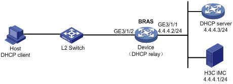
Procedure
1. Configure the DHCP server:
# Enable DHCP.
<DHCP-server> system-view
[DHCP-server] dhcp enable
# Create an IP address pool named pool1 and enter its view.
[DHCP-server] dhcp server ip-pool pool1
# Specify primary subnet 192.168.0.0/24 for dynamic allocation in DHCP address pool pool1.
[DHCP-server-dhcp-pool-pool1] network 192.168.0.0 24
# Specify gateway address 192.168.0.1 in DHCP address pool pool1.
[DHCP-server-dhcp-pool-pool1] gateway-list 192.168.0.1
# Specify DNS server address 8.8.8.8 in DHCP address pool pool1.
[DHCP-server-dhcp-pool-pool1] dns-list 8.8.8.8
# Exclude IP address 192.168.0.1 from dynamic allocation in DHCP address pool pool1.
[DHCP-server-dhcp-pool-pool1] forbidden-ip 192.168.0.1
[DHCP-server-dhcp-pool-pool1] quit
# Configure a static route to specify the next hop of DHCP replies destined to network segment 192.168.0.0 as the IP address of the interface connected to the DHCP client, 4.4.4.2.
[DHCP-server] ip route-static 192.168.0.0 24 4.4.4.2
2. Configure the BRAS:
a. Configure IP addresses for interfaces. (Details not shown.)
b. Configure the DHCP relay agent:
# Enable DHCP.
<Device> system-view
[Device] dhcp enable
# Enable the DHCP relay agent to record client information in relay entries.
[Device] dhcp relay client-information record
# Disable the DHCP relay agent from periodically refreshing dynamic relay entries.
[Device] undo dhcp relay client-information refresh enable
# Enable DHCP server proxy on the DHCP relay agent on GigabitEthernet 3/1/2.
[Device] interface gigabitethernet 3/1/2
[Device–GigabitEthernet3/1/2] dhcp select relay proxy
[Device–GigabitEthernet3/1/2] quit
# Create an IP address pool named pool1 for the DHCP relay agent.
[Device] dhcp server ip-pool pool1
# Specify gateway address 192.168.0.1 in DHCP address pool pool1.
[Device-dhcp-pool-pool1] gateway-list 192.168.0.1 export-route
# Specify DHCP server 4.4.4.3 in DHCP address pool pool1.
[Device-dhcp-pool-pool1] remote-server 4.4.4.3
[Device-dhcp-pool-pool1] quit
c. Configure the IP address of the portal authentication server newpt as 4.4.4.1 and the plaintext key 123456.
[Device] portal server newpt
[Device-portal-server-newpt] ip 4.4.4.1 key simple 123456
[Device-portal-server-newpt] quit
d. Configure a RADIUS scheme:
# Create a RADIUS scheme named rs1 and enter its view.
[Device] radius scheme rs1
# Configure primary servers and keys for authentication and accounting.
[Device-radius-rs1] primary authentication 4.4.4.1
[Device-radius-rs1] primary accounting 4.4.4.1
[Device-radius-rs1] key authentication simple 123456
[Device-radius-rs1] key accounting simple 123456
# Exclude the ISP name from the username sent to the RADIUS server.
[Device-radius-rs1] user-name-format without-domain
[Device-radius-rs1] quit
e. Configure the preauthentication ISP domain and Web authentication ISP domain:
# Configure the ISP domain dm1 for IPoE user preauthentication.
[Device] domain name dm1
[Device-isp-dm1] authentication ipoe none
[Device-isp-dm1] authorization ipoe none
[Device-isp-dm1] accounting ipoe none
# Configure the authorized IP address pool and user group in ISP domain dm1.
[Device-isp-dm1] authorization-attribute user-group web
[Device-isp-dm1] authorization-attribute ip-pool pool1
# Configure the Web authentication page URL and Web server IP address in ISP domain dm1.
[Device-isp-dm1] web-server url http://4.4.4.1:8080/portal/
[Device-isp-dm1] web-server ip 4.4.4.1
[Device-isp-dm1] quit
# Configure the ISP domain dm2 for IPoE user Web authentication.
[Device] domain name dm2
[Device-isp-dm2] authentication ipoe radius-scheme rs1
[Device-isp-dm2] authorization ipoe radius-scheme rs1
[Device-isp-dm2] accounting ipoe radius-scheme rs1
[Device-isp-dm2] quit
f. Configure IPoE:
# Enable IPoE and configure Layer 2 access mode on GigabitEthernet 3/1/2.
[Device] interface gigabitethernet 3/1/2
[Device–GigabitEthernet3/1/2] ip subscriber l2-connected enable
# Configure Web authentication for IPoE users on GigabitEthernet 3/1/2.
[Device–GigabitEthernet3/1/2] ip subscriber authentication-method web
The operation may cut all users on this interface. Continue?[Y/N]:y
# Configure the ISP domain dm1 for preauthentication and the ISP domain dm2 for Web authentication on GigabitEthernet 3/1/2.
[Device–GigabitEthernet3/1/2] ip subscriber pre-auth domain dm1
[Device–GigabitEthernet3/1/2] ip subscriber web-auth domain dm2
[Device–GigabitEthernet3/1/2] quit
3. Configure the RADIUS server:
a. Configure the access device:
i Log in to the IMC platform and click the User tab.
ii Select User Access Policy > Access Device Management > Access Device from the navigation tree to open the access device configuration page.
iii Click Add to open the page as shown in Figure 140.
iv Enter the shared key radius.
v Use the default settings for other parameters.
Figure 140 Adding an access device
vi Click Add Manually in the Device List area to open the page as shown in Figure 141.
vii Enter the access device's IP address 4.4.4.2.
viii Click OK.
Figure 141 Manually adding an access device
a. Add an access policy:
i Select User Access Policy > Access Policy from the navigation tree to open the access policy page.
ii Click Add to open the page as shown in Figure 142.
iii Enter the access policy name.
iv Select EAP for Certificate Authentication.
v Use the default settings for other parameters.
vi Click OK.
Figure 142 Adding an access policy
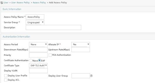
a. Add an access service:
i Select User Access Policy > Access Service from the navigation tree to open the access service page.
ii Click Add to open the page as shown in Figure 143.
iii Enter the service name.
iv Select AccessPolicy from the Default Access Policy list.
v Use the default settings for other parameters.
vi Click OK.
Figure 143 Adding an access service
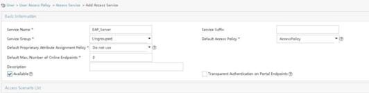
a. Add an access user:
i Select Access User > All Access Users from the navigation tree to open the access user page.
ii Click Add to open the page as shown in Figure 144.
iii Select an access user.
iv Set the password.
v Click OK.
Figure 144 Adding an access user
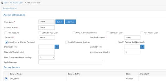
# Select User Access Policy > Service Parameters > Validate System Configuration from the navigation tree to validate the configurations.
4. Configure the portal server (IMC PLAT 7.1):
|
|
NOTE: This example uses a portal server running IMC PLAT 7.1(E0303), IMC EIA 7.1(F0303), and IMC EIP 7.1(F0303). |
a. Configure the portal homepage:
i Select User Access Policy > Portal Service > Server from the navigation tree to open the portal server configuration page, as shown in Figure 145.
ii Click OK.
Figure 145 Portal server configuration page
a. Configure portal authentication source IP address range:
i Select User Access Policy > Portal Service > IP Group from the navigation tree to open the portal IP address group configuration page.
ii Click Add to open the page as shown in Figure 146.
iii Enter the IP group name IPoE_Web_User.
iv Enter the start IP address (192.168.0.1) and end IP address (192.168.0.255) of the IP group. Make sure the host IP address is in the IP group.
v Click OK.
Figure 146 Adding an IP address group
a. Add a portal device:
i Select User Access Policy > Portal Service > Device from the navigation tree to open the portal device configuration page.
ii Click Add to open the page as shown in Figure 147.
iii Enter the device name NAS.
iv Enter the IP address of the portal packets' outgoing interface GigabitEthernet 3/1/1 (4.4.4.2).
v Enter the key 123456
vi Select Directly Connect for access method.
vii Click OK.
Figure 147 Adding a portal device
a. Associate the portal device with the IP address group:
i Click the icon in the Port Group Information Management column of device NAS to open the port group configuration page, as shown in Figure 148.
ii Click Add to open the page as shown in Figure 149.
iii Enter the port group name group.
iv Select the configured IP address group IPoE_Web_User. Make sure the IP address used by the user to access the network is within this IP address group.
v Select EAP from the Authentication Type list.
vi Click OK.
Figure 149 Port group configuration
a. From the navigation tree, select User Access Manager > Service Parameters > Validate System Configuration to validate the settings.
Verifying the configuration
# Display IPoE session information to verify that the host has passed preauthentication.
[Device] display ip subscriber session verbose
Basic:
Description : -
Username : 0015e947f4d4
Domain : dm1
VPN instance : N/A
IP address : 192.168.0.2
User address type : N/A
MAC address : 0015-e947-f4d4
Service-VLAN/Customer-VLAN : -/-
Access interface : GE3/1/2
User ID : 0x3808001c
VPI/VCI(for ATM) : -/-
VSI Index : -
VSI link ID : -
VXLAN ID : -
DNS servers : 8.8.8.8
IPv6 DNS servers : N/A
DHCP lease : 86400 sec
DHCP remain lease : N/A
Access time : Aug 2 16:51:28 2016
Online time(hh:mm:ss) : 00:00:20
Service node : Slot 3 CPU 0
Authentication type : Web pre-auth
IPv4 access type : DHCP
IPv4 detect state : Detecting
State : Online
AAA:
ITA policy name : N/A
IP pool : pool1
IPv6 pool : N/A
Primary DNS server : N/A
Secondary DNS server : N/A
Primary IPv6 DNS server : N/A
Secondary IPv6 DNS server : N/A
Session idle cut : N/A
Session duration : N/A, remaining: N/A
Traffic quota : N/A
Traffic remained : N/A
Acct start-fail action : Online
Acct update-fail action : Online
Acct quota-out action : Offline
Dual-stack accounting mode : Merge
Max IPv4 multicast addresses: 4
IPv4 multicast address list : N/A
Max IPv6 multicast addresses: 4
IPv6 multicast address list : N/A
Accounting start time : Aug 2 16:51:28 2016
Redirect URL : http://4.4.4.1:8080/portal/
Subscriber ID : -
QoS:
User profile : N/A
Session group profile : N/A
User group ACL : web (active)
Inbound CAR : N/A
Outbound CAR : N/A
Inbound user priority : N/A
Outbound user priority : N/A
Flow statistic:
Uplink packets/bytes : 0/0
Downlink packets/bytes : 0/0
IPv6 uplink packets/bytes : 0/0
IPv6 downlink packets/bytes : 0/0
# As shown in Figure 150, open the iNode login page after preauthentication. Enter the server address, the username, and the password on the page. Click the dropdown arrow next to Disconnect. The page shown in Figure 151 opens.
# As shown in Figure 151, select Certificate Authentication in the Enable advanced authentication list and select an authentication type (EAP-TLS in this example) in the Advanced tab of the Properties dialog box. In the Certificate Options area, click Client Certificate, select a certificate on the window that opens, and select Validate server certificate chain.
Figure 151 Setting iNode client attribute
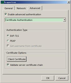
# After the configuration of iNode client attribute, click OK to return to the iNode client authentication page.
# Click Connect on the iNode authentication page to perform EAP authentication. Display IPoE session information to verify that the host has passed Web authentication and come online.
[Device] display ip subscriber session verbose
Basic:
Description : -
Username : client
Domain : dm2
VPN instance : N/A
IP address : 192.168.0.2
User address type : N/A
MAC address : 0015-e947-f4d4
Service-VLAN/Customer-VLAN : -/-
Access interface : GE3/1/2
User ID : 0x3808001c
VPI/VCI(for ATM) : -/-
VSI Index : -
VSI link ID : -
VXLAN ID : -
DNS servers : 8.8.8.8
IPv6 DNS servers : N/A
DHCP lease : 86400 sec
DHCP remain lease : N/A
Access time : Aug 2 16:52:28 2016
Online time(hh:mm:ss) : 00:00:20
Service node : Slot 3 CPU 0
Authentication type : Web
IPv4 access type : DHCP
IPv4 detect state : Detecting
State : Online
AAA:
ITA policy name : N/A
IP pool : pool1
IPv6 pool : N/A
Primary DNS server : N/A
Secondary DNS server : N/A
Primary IPv6 DNS server : N/A
Secondary IPv6 DNS server : N/A
Session idle cut : N/A
Session duration : N/A, remaining: N/A
Traffic quota : N/A
Traffic remained : N/A
Acct start-fail action : Online
Acct update-fail action : Online
Acct quota-out action : Offline
Dual-stack accounting mode : Merge
Max IPv4 multicast addresses: 4
IPv4 multicast address list : N/A
Max IPv6 multicast addresses: 4
IPv6 multicast address list : N/A
Accounting start time : Aug 2 16:52:28 2016
Subscriber ID : -
QoS:
User profile : N/A
Session group profile : N/A
User group ACL : N/A
Inbound CAR : N/A
Outbound CAR : N/A
Inbound user priority : N/A
Outbound user priority : N/A
Flow statistic:
Uplink packets/bytes : 0/0
Downlink packets/bytes : 0/0
IPv6 uplink packets/bytes : 0/0
IPv6 downlink packets/bytes : 0/0
# Click Disconnect on the iNode login page as shown in Figure 150.
# Verify that the user returns to the preauthentication status.
[Device] display ip subscriber session verbose
Basic:
Description : -
Username : 0015e947f4d4
Domain : dm1
VPN instance : N/A
IP address : 192.168.0.2
User address type : N/A
MAC address : 0015-e947-f4d4
Service-VLAN/Customer-VLAN : -/-
Access interface : GE3/1/2
User ID : 0x3808001c
VPI/VCI(for ATM) : -/-
VSI Index : -
VSI link ID : -
VXLAN ID : -
DNS servers : 8.8.8.8
IPv6 DNS servers : N/A
DHCP lease : 86400 sec
DHCP remain lease : N/A
Access time : Aug 2 16:52:59 2016
Online time(hh:mm:ss) : 00:00:20
Service node : Slot 3 CPU 0
Authentication type : Web pre-auth
IPv4 access type : DHCP
IPv4 detect state : Detecting
State : Online
AAA:
ITA policy name : N/A
IP pool : pool1
IPv6 pool : N/A
Primary DNS server : N/A
Secondary DNS server : N/A
Primary IPv6 DNS server : N/A
Secondary IPv6 DNS server : N/A
Session idle cut : N/A
Session duration : N/A, remaining: N/A
Traffic quota : N/A
Traffic remained : N/A
Acct start-fail action : Online
Acct update-fail action : Online
Acct quota-out action : Offline
Dual-stack accounting mode : Merge
Max IPv4 multicast addresses: 4
IPv4 multicast address list : N/A
Max IPv6 multicast addresses: 4
IPv6 multicast address list : N/A
Accounting start time : Aug 2 16:52:59 2016
Redirect URL : http://4.4.4.1:8080/portal/
Subscriber ID : -
QoS:
User profile : N/A
Session group profile : N/A
User group ACL : web (active)
Inbound CAR : N/A
Outbound CAR : N/A
Inbound user priority : N/A
Outbound user priority : N/A
Flow statistic:
Uplink packets/bytes : 0/0
Downlink packets/bytes : 0/0
IPv6 uplink packets/bytes : 0/0
IPv6 downlink packets/bytes : 0/0
Example: Configuring a roaming user
Network configuration
As shown in Figure 152, the host accesses the BRAS as a roaming user. The host obtains an IP address from the DHCP server. The BRAS performs AAA for the host through the RADIUS server.
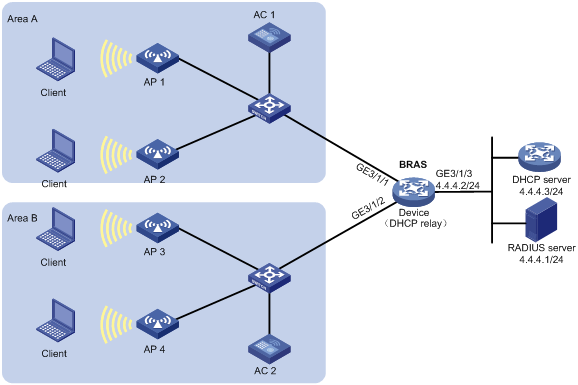
Procedure
|
|
NOTE: In this example, when a user obtains an IP address through DHCP, the DHCP packets do not carry Option 60. |
1. Configure the RADIUS server: (This section uses the Linux Free RADIUS server as an example.)
# Add BRAS IP address 4.4.4.2 and secret radius to the clients.conf file.
client 4.4.4.2/32 {
ipaddr = 4.4.4.2
netmask=32
secret=radius
}
# Add the username and password to the users user information file. The username is the host MAC address and the password is radius.
000c29a6b656 Cleartext-Password :="radius"
2. Configure the DHCP server:
a. Configure the DHCPv4 address pool:
# Enable DHCP.
<DHCP-server> system-view
[DHCP-server] dhcp enable
# Create a DHCPv4 address pool named pool1 and enter its view.
[DHCP-server] dhcp server ip-pool pool1
# Specify the subnet 3.3.3.0/24 for dynamic allocation in the pool.
[DHCP-server-dhcp-pool-pool1] network 3.3.3.0 24
# Specify gateway address 3.3.3.1 in the address pool.
[DHCP-server-dhcp-pool-pool1] gateway-list 3.3.3.1
# Exclude IP address 3.3.3.1 from dynamic allocation in the pool.
[DHCP-server-dhcp-pool-pool1] forbidden-ip 3.3.3.1
[DHCP-server-dhcp-pool-pool1] quit
# Configure a static route to specify the next hop of DHCP replies destined to network segment 3.3.3.0 as the IP address of the interface connected to the DHCP client, 4.4.4.2.
[DHCP-server] ip route-static 3.3.3.0 24 4.4.4.2
3. Configure the BRAS:
a. Configure IP addresses for interfaces. (Details not shown.)
b. Configure a RADIUS scheme:
# Create a RADIUS scheme named rs1 and enter its view.
<Device> system-view
[Device] radius scheme rs1
# Configure primary servers and keys for authentication and accounting.
[Device-radius-rs1] primary authentication 4.4.4.1
[Device-radius-rs1] primary accounting 4.4.4.1
[Device-radius-rs1] key authentication simple radius
[Device-radius-rs1] key accounting simple radius
# Exclude the ISP name from the username sent to the RADIUS server.
[Device-radius-rs1] user-name-format without-domain
[Device-radius-rs1] quit
c. Configure the ISP domain:
# Create an ISP domain named dm1 and enter its view.
[Device] domain name dm1
# Configure ISP domain dm1 to use RADIUS scheme rs1 and authorize a relay address pool.
[Device-isp-dm1] authentication ipoe radius-scheme rs1
[Device-isp-dm1] authorization ipoe radius-scheme rs1
[Device-isp-dm1] accounting ipoe radius-scheme rs1
[Device-isp-dm1] authorization-attribute ip-pool pool1
[Device-isp-dm1] quit
d. Configure the DHCP relay agent:
# Enable DHCP.
[Device] dhcp enable
# Enable the DHCP relay agent to record client information in relay entries.
[Device] dhcp relay client-information record
# Disable the DHCP relay agent from periodically refreshing dynamic relay entries.
[Device] undo dhcp relay client-information refresh enable
# Enable the DHCP server proxy on the relay agent on GigabitEthernet 1/0/1 and GigabitEthernet 1/0/2.
[Device] interface range gigabitethernet 1/0/1 gigabitethernet 1/0/2
[Device–if-range] dhcp select relay proxy
# Configure DHCP on GigabitEthernet 1/0/1 or GigabitEthernet 1/0/2 to release the online lease for a MAC address of a user and then allocate an IP address to the user after GigabitEthernet 1/0/1 or GigabitEthernet 1/0/2 receives a DHCP-DISCOVER packet from an online user whose physical location changes and MAC address does not change.
|
|
NOTE: When an attacker uses a DHCP-DISCOVER packet with a spoofing MAC address to request coming online, the corresponding normally online user might go offline. To use the dhcp session-mismatch action fast-renew command, make sure no attacks exist in the network. |
[Device–if-range] dhcp session-mismatch action fast-renew
[Device–if-range] quit
# Create a DHCP relay agent address pool pool1, specify a gateway address in the DHCP address pool, and specify a DHCP server for the address pool.
[Device] dhcp server ip-pool pool1
[Device-dhcp-pool-pool1] gateway-list 3.3.3.1 export-route
[Device-dhcp-pool-pool1] remote-server 4.4.4.3
[Device-dhcp-pool-pool1] quit
e. Configure IPoE:
# Enable IPoE and configure Layer 2 access mode on GigabitEthernet 3/1/1.
[Device] interface gigabitethernet 3/1/1
[Device–GigabitEthernet3/1/1] ip subscriber l2-connected enable
# Enable DHCPv4 packet initiation on GigabitEthernet 3/1/1.
[Device–GigabitEthernet3/1/1] ip subscriber initiator dhcp enable
# Enable ARP packet initiation.
[Device–GigabitEthernet3/1/2] ip subscriber initiator arp enable
# Enable unclassified-IP packet initiation on GigabitEthernet 3/1/1.
[Device–GigabitEthernet3/1/1] ip subscriber initiator unclassified-ip enable matching-user
# Enabling roaming for IPoE individual users on GigabitEthernet 3/1/1.
[Device–GigabitEthernet3/1/1] ip subscriber roaming enable
# Specify dm1 as the ISP domain for DHCP users.
[Device–GigabitEthernet3/1/1] ip subscriber dhcp domain dm1
# Configure plaintext password radius for authentication.
[Device–GigabitEthernet3/1/1] ip subscriber password plaintext radius
[Device–GigabitEthernet3/1/1] quit
# Enable IPoE and configure Layer 2 access mode on GigabitEthernet 3/1/2.
[Device–GigabitEthernet3/1/2] ip subscriber l2-connected enable
# Enable DHCPv4 packet initiation on GigabitEthernet 3/1/2.
[Device–GigabitEthernet3/1/2] ip subscriber initiator dhcp enable
# Enable ARP packet initiation on GigabitEthernet 3/1/2.
[Device–GigabitEthernet3/1/2] ip subscriber initiator arp enable
# Enable unclassified-IPv4 packet initiation on GigabitEthernet 3/1/2.
[Device–GigabitEthernet3/1/2] ip subscriber initiator unclassified-ip enable matching-user
# Enabling roaming for IPoE individual users on GigabitEthernet 3/1/2.
[Device–GigabitEthernet3/1/2] ip subscriber roaming enable
# Specify dm1 as the ISP domain for DHCP users.
[Device–GigabitEthernet3/1/2] ip subscriber dhcp domain dm1
# Configure plaintext password radius for authentication.
[Device–GigabitEthernet3/1/2] ip subscriber password plaintext radius
[Device–GigabitEthernet3/1/2] quit
Verifying the configuration
# Display IPoE session information to verify that the host in area A has come online.
[Device] display ip subscriber session
Type: D-DHCP S-Static U-Unclassified-IP N-NDRS
Interface IP address MAC address Type State
IPv6 address SVLAN/CVLAN VXLAN
Username
GE3/1/1 3.3.3.2 000c-29a6-b656 D/- Online
- -/- -
000c29a6b656
# Display IPoE session information to verify that the user has roamed from area A to area B.
[Device] display ip subscriber session
Type: D-DHCP S-Static U-Unclassified-IP N-NDRS
Interface IP address MAC address Type State
IPv6 address SVLAN/CVLAN VXLAN
Username
GE3/1/2 3.3.3.2 000c-29a6-b656 D/- Online
- -/- -
000c29a6b656
Troubleshooting IPoE
DHCP clients failed to come online
Symptom
DHCP clients cannot come online, although network connections and interface IPoE configurations are correct.
Solution
To solve the problem:
1. Use debug commands or a packet analyzer to check DHCP packets from the DHCP client.
By default, DHCPv4 and DHCPv6 clients use ISP domains specified in Option 60 and Option 16/Option 17, respectively.
2. If the DHCPv4 packet carries Option 60 or the DHCPv6 packet carries Option 16/Option 17, verify that the ISP domain in the option exists on the BRAS.
3. If the DHCP packet does not carry Option 60 or Option 16/Option 17, verify that the ISP domain specified on the interface exists on the BRAS.
4. If the problem persists, contact H3C Support.