- Table of Contents
-
- 16-BRAS Services Configuration Guide
- 00-Preface
- 01-BRAS services overview
- 02-AAA configuration
- 03-ANCP configuration
- 04-PPP configuration
- 05-ITA configuration
- 06-EDSG configuration
- 07-DHCP configuration
- 08-DHCPv6 configuration
- 09-User profile configuration
- 10-Connection limit configuration
- 11-L2TP configuration
- 12-PPPoE configuration
- 13-Portal configuration
- 14-IPoE configuration
- Related Documents
-
| Title | Size | Download |
|---|---|---|
| 12-PPPoE configuration | 291.30 KB |
Restrictions and guidelines: PPPoE configuration
PPPoE server tasks at a glance
Setting the maximum number of PPPoE sessions
Configuring the per-slot user count trap feature
Limiting the PPPoE access rate
Configuring the NAS-Port-ID attribute
Configuring NAS-Port-ID binding for PPPoE access users
Setting a service name for the PPPoE server
Setting the maximum number of PADI packets that the device can receive per second
Configuring PPPoE user blocking
Configuring PPPoE protocol packet attack prevention
Forbidding PPPoE users from coming online through an interface
Configuring the interface-down policy for PPPoE users on an interface
Display and maintenance commands for PPPoE
Display and maintenance commands for PPPoE server
Example: Configuring the PPPoE server to assign IPv4 addresses through a PPP address pool
Example: Configuring the PPPoE server to assign IPv4 addresses through the local DHCP server
Example: Configuring the PPPoE server to assign IPv4 addresses through a remote DHCP server
Example: Configuring the PPPoE server to assign IPv6 addresses through the IA_NA+IA_PD method
Example: Configuring PPPoE server RADIUS-based IP address assignment
Configuring PPPoE
About PPPoE
Point-to-Point Protocol over Ethernet (PPPoE) extends PPP by transporting PPP frames encapsulated in Ethernet over point-to-point links.
PPPoE specifies the methods for establishing PPPoE sessions and encapsulating PPP frames over Ethernet. PPPoE requires a point-to-point relationship between peers instead of a point-to-multipoint relationship as in multi-access environments such as Ethernet. PPPoE provides Internet access for the hosts in an Ethernet through a remote access device and implement access control, authentication, and accounting on a per-host basis. Integrating the low cost of Ethernet and scalability and management functions of PPP, PPPoE gained popularity in various application environments, such as residential access networks.
For more information about PPPoE, see RFC 2516.
PPPoE network structure
PPPoE uses the client/server model. The PPPoE client initiates a connection request to the PPPoE server. After session negotiation between them is complete, a session is established between them, and the PPPoE server provides access control, authentication, and accounting to the PPPoE client.
PPPoE network structures are classified into router-initiated and host-initiated network structures depending on the starting point of the PPPoE session.
Router-initiated network structure
As shown in Figure 1, the PPPoE session is established between routers (Router A and Router B). All hosts share one PPPoE session for data transmission without being installed with PPPoE client software. This network structure is typically used by enterprises.
Figure 1 Router-initiated network structure
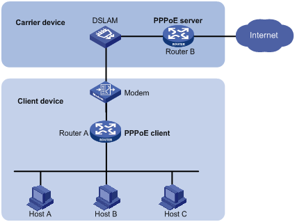
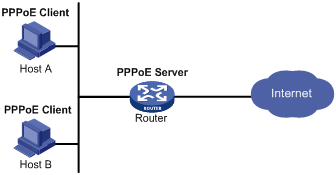
Host-initiated network structure
As shown in Figure 2, a PPPoE session is established between each host (PPPoE client) and the carrier router (PPPoE server). The service provider assigns an account to each host for billing and control. The host must be installed with PPPoE client software.
Figure 2 Host-initiated network structure
Protocols and standards
RFC 2516: A Method for Transmitting PPP Over Ethernet (PPPoE)
Restrictions and guidelines: PPPoE configuration
The device can only act as a PPPoE server.
This feature is available only when the system operates in standard mode. For more information about the system operating modes, see device management in Fundamentals Configuration Guide.
This feature is supported only on CSPEX (except CSPEX-1104-E)/CEPC cards.
When you configure the PPPoE server to assign IPv6 addresses through the IA_NA method, only IA_NA access in CPE mode and directly connecting endpoints to the BRAS device through IA_NA access are supported in the current software version. When you directly connect endpoints to the BRAS device through IA_NA access, follow these restrictions and guidelines:
· For some endpoints (for example, endpoints running Windows) to operate properly, the following requirements must be met:
¡ The BRAS device also acts as the DHCP server.
¡ The address-alloc-mode interface-id command is configured.
· When the BRAS acts as a DHCP relay agent, you must execute the ipv6 dhcp relay client-information record command on the access interfaces.
Make sure the statistics polling interval is 300 seconds when you configure the PPPoE server. For more information about the statistics polling interval, see Ethernet interface configuration in Interface Configuration Guide.
Set the keepalive interval on the VT interface to no less than 60 seconds when the following requirements are met:
· You need to separate the accounting for IPv4 and IPv6 traffic of a PPPoE user.
· The PPPoE user goes online through a Layer 3 aggregate interface or a Layer 3 aggregate subinterface.
For more information about the keepalive interval on a VT interface, see PPP configuration in BRAS Services Configuration Guide.
When a subinterface has a large number of PPPoE users online, as a best practice, do not configure VRRP control VLANs on the subinterface. For more information about VRRP, see VRRP configuration in High Availability Configuration Guide.
In PPPoE applications, the advertisement pushing function takes effect only on HTTP packets with port number 80 or 8080.
The PPPoE server supports the following interfaces:
· Layer 3 Ethernet interfaces/subinterfaces.
· Layer 3 aggregate interfaces/subinterfaces.
· L3VE interfaces/subinterfaces.
Configuring the PPPoE server
PPPoE server tasks at a glance
To configure PPPoE server, perform the following tasks:
1. Configuring a PPPoE session
2. (Optional.) Setting the maximum number of PPPoE sessions
3. (Optional.) Configuring the per-slot user count trap feature
4. (Optional.) Enabling PPPoE logging
5. (Optional.) Limiting the PPPoE access rate
6. (Optional.) Configuring the NAS-Port-ID attribute
7. Configuring NAS-Port-ID binding for PPPoE access users
Perform this task if you need to acquire the physical location of the PPPoE user access interface by NAS-Port-ID.
8. (Optional.) Setting a service name for the PPPoE server
9. (Optional.) Setting the maximum number of PADI packets that the device can receive per second
10. (Optional.) Configuring PPPoE user blocking
11. Configuring PPPoE protocol packet attack prevention
12. Forbidding PPPoE users from coming online through an interface
13. Configuring the interface-down policy for PPPoE users on an interface
Configuring a PPPoE session
1. Enter system view.
system-view
2. Create a VT interface and enter VT interface view.
interface virtual-template number
3. Set PPP parameters.
For more information setting PPP parameters, see PPP configuration in BRAS Services Configuration Guide.
When configuring PPP authentication, use the PPPoE server as the authenticator.
4. Return to system view.
quit
5. Enter interface view.
interface interface-type interface-number
6. Enable the PPPoE server on the interface and bind this interface to the specified VT interface.
pppoe-server bind virtual-template number
By default, the PPPoE server is disabled on the interface.
7. (Optional.) Configure an access concentrator (AC) name for the PPPoE server.
pppoe-server tag ac-name name
By default, the AC name for the PPPoE server is the device name.
PPPoE clients can choose a PPPoE server according to the AC name.
8. (Optional.) Enable the PPPoE server to support the ppp-max-payload tag and specify a range for the PPP maximum payload.
pppoe-server tag ppp-max-payload [ minimum minvalue maximum maxvalue ]
By default, The PPPoE server does not support the ppp-max-payload tag.
9. (Optional) Set the response delay time for user access.
pppoe-server access-delay delay-time [ even-mac | odd-mac ]
By default, no response delay time is set.
10. Return to system view.
quit
11. Configure the PPPoE server to perform authentication, authorization, and accounting for PPP users.
For more information, see AAA configuration in BRAS Services Configuration Guide.
Setting the maximum number of PPPoE sessions
About the PPPoE session upper limit
PPPoE can establish a session when none of the following limits are reached:
· Limit for a user on an interface.
· Limit for a VLAN on an interface.
· Limit on an interface.
· Limit on a card.
Restrictions and guidelines for maximum number of PPPoE sessions
If the configured limit is smaller than the number of existing online sessions on the interface, the configuration succeeds. The configuration does not affect the existing online sessions. However, new sessions cannot be established on the interface.
The total maximum number of PPPoE sessions set for all cards cannot be greater than the maximum number of PPPoE sessions supported by the device.
Setting the maximum number of PPPoE sessions in interface view
1. Enter system view.
system-view
2. Enter interface view.
interface interface-type interface-number
The PPPoE server is enabled on the interface.
3. Set the maximum number of PPPoE sessions.
¡ Set the maximum number of PPPoE sessions on an interface.
pppoe-server session-limit number
By default, the number of PPPoE sessions on an interface is not limited.
¡ Set the maximum number of PPPoE sessions for a VLAN.
pppoe-server session-limit per-vlan number
By default, the number of PPPoE sessions for a VLAN on an interface is not limited.
¡ Set the maximum number of PPPoE sessions for a user.
pppoe-server session-limit per-mac number
By default, a user is allowed to create a maximum of 1 PPPoE sessions.
Setting the maximum number of PPPoE sessions in system view
1. Enter system view.
system-view
2. Set the maximum number of PPPoE sessions.
In standalone mode:
pppoe-server session-limit slot slot-number total number
In IRF mode:
pppoe-server session-limit chassis chassis-number slot slot-number total number
By default, the number of PPPoE sessions is not limited.
Configuring the per-slot user count trap feature
About this task
You can use this feature to set the per-slot user count alarm threshold. When the user count on a slot exceeds the threshold, an alarm is triggered automatically. Then, the administrator can promptly know the online user conditions of the network.
This feature counts only the number of IPoE users and PPPoE users.
· A dual-stack PPPoE user is counted as one user.
· A dual-stack IPoE user is counted as two users.
· For IPoE leased users, one interface-leased user is counted as two users, and one subnet-leased user is counted as one user.
· For IPoE leased subusers, one subuser is counted as one user.
Suppose the per-slot maximum user count allowed is a and the per-slot user count alarm threshold is b. The following rules apply:
· When the user count on a slot exceeds a×b, the alarm information is output.
· When the user count on a slot drops within the normal range, the alarm clearing information is output.
In some special cases, the user count on a slot frequently changes in the critical range, which causes frequent output of alarm information and alarm clearing information. To avoid this problem, the system introduces a buffer area when the user count on a slot drops below the threshold. The buffer area size is 10% of the threshold set. Suppose the buffer area size is c. Then, c=a×b÷10. When the user count on a slot drops below a×b-c, the alarm clearing information is output.
For example, suppose a is 1000 and b is 80%. Then, c= a×b÷10=1000×80%÷10=80.
· When the user count on a slot exceeds a×b=1000×80%=800, the alarm information is output.
· When the user count on a slot drops below a×b-c=800-80=720, the alarm clearing information is output.
The alarm information and alarm clearing information output both contain the logs and traps. For traps to be correctly sent to the NMS host, you must execute the snmp-agent trap enable slot-user-warning-threshold command in addition to configuring the SNMP alarm feature correctly.
Procedure
1. Enter system view.
system-view
2. Set the per-slot user count alarm threshold.
slot-user-warning-threshold threshold-value
By default, the per-slot user count alarm threshold is 100.
3. Enable the per-slot user count trap feature.
snmp-agent trap enable slot-user-warning-threshold
By default, the per-slot user count trap feature is disabled.
Enabling PPPoE logging
About PPPoE logging
The PPPoE logging feature enables the device to generate PPPoE logs and send them to the information center. Logs are generated when the following requirements are met:
· The number of PPPoE sessions reaches the upper limit for an interface, user, VLAN, or the system.
· New users request to come online.
A log entry records the interface-based, MAC-based, VLAN-based, or system-based session limit. For information about the log destination and output rule configuration in the information center, see Network Management and Monitoring Configuration Guide.
Restrictions and guidelines
As a best practice, disable this feature to prevent excessive PPP log output.
Procedure
1. Enter system view.
system-view
2. Enable PPPoE logging.
pppoe-server log enable
By default, PPPoE logging is disabled.
Limiting the PPPoE access rate
About the PPPoE access rate
The device can limit the rate at which a user (identified by an MAC address) can create PPPoE sessions on an interface. If the number of PPPoE requests within the monitoring time reaches the configured threshold, the device discards the excessive requests, and outputs log messages. If the blocking time is set to 0, the device does not block any requests, and it only outputs log messages.
The device uses a monitoring table and a blocking table to control PPP access rates:
· Monitoring table—Stores a maximum of 8000 monitoring entries. Each entry records the number of PPPoE sessions created by a user within the monitoring time. When the monitoring entries reach the maximum, the system stops monitoring and blocking session requests from new users. The aging time of monitoring entries is determined by the session-request-period argument. When the timer expires, the system starts a new round of monitoring for the user.
· Blocking table—Stores a maximum of 8000 blocking entries. The system creates a blocking entry if the access rate of a user reaches the threshold, and blocks requests from that user. When the blocking entries reach the maximum number, the system stops blocking session requests from new users and it only outputs log messages. The aging time of the blocking entries is determined by the blocking-period argument. When the timer expires, the system starts a new round of monitoring for the user.
Restrictions and guidelines
If the access rate setting is changed, the system removes all monitoring and blocking entries, and uses the new settings to limit PPPoE access rates.
Procedure
1. Enter system view.
system-view
2. Enter interface view.
interface interface-type interface-number
The PPPoE server is enabled on the interface.
3. Set the PPPoE access limit.
pppoe-server throttle per-mac session-requests session-request-period blocking-period
By default, the PPPoE access rate is not limited.
Configuring the NAS-Port-ID attribute
About the NAS-Port-ID attribute
The PPPoE server on a BRAS device uses the RADIUS NAS-Port-ID attribute to send the access line ID received from a DSLAM device to the RADIUS server. The access line ID includes the circuit-id and remote-id. The RADIUS server compares the received NAS-Port-ID attribute with the local line ID information to verify the location of the user.
You can configure the content of the NAS-Port-ID attribute that the PPPoE server sends to the RADIUS server.
Restrictions and guidelines
If the attribute 87 format command is executed in RADIUS scheme view, the format of the NAS-Port-ID attribute sent to the RADIUS server is determined by using this command. In this case, the NAS-Port-ID attribute format defined in PPPoE does not take effect. For more information about the attribute 87 format command, see AAA commands in BRAS Services Command Reference.
Procedure
1. Enter system view.
system-view
2. Enter interface view.
interface interface-type interface-number
The PPPoE server is enabled on the interface.
3. Configure the content of the NAS-Port-ID attribute.
pppoe-server access-line-id content { all [ separator ] | circuit-id | remote-id }
By default, the NAS-Port-ID attribute contains only the circuit-id.
4. Configure the NAS-Port-ID attribute to include the BAS information automatically.
pppoe-server access-line-id bas-info [ cn-163 | cn-163-redback ]
By default, the NAS-Port-ID attribute does not include the BAS information automatically.
5. Configure the PPPoE server to trust the access line ID in received packets.
pppoe-server access-line-id trust
By default, the PPPoE server does not trust the access line ID in received packets.
6. Configure the format that is used to parse the circuit-id.
pppoe-server access-line-id circuit-id parse-mode { cn-telecom | tr-101 }
The default mode is TR-101.
7. Configure the transmission format for the circuit-id.
pppoe-server access-line-id circuit-id trans-format { ascii | hex }
The default format is a string of characters.
8. Configure the transmission format for the remote-id.
pppoe-server access-line-id remote-id trans-format { ascii | hex }
The default format is a string of characters.
9. Insert the VXLAN information into the NAS-Port-ID attribute.
pppoe-server access-line-id vxlan-info enable
By default, VXLAN information is not inserted into the NAS-Port-ID attribute.
Configuring NAS-Port-ID binding for PPPoE access users
About NAS-Port-ID binding for PPPoE access users
A device uses information about the interface through which a user comes online to fill in the NAS-Port-ID attribute and sends it to the RADIUS server by default. In some special applications, when you need to manually specify the access interface information to be filled in the NAS-Port-ID attribute, you can use this command. For example, suppose the RADIUS server restricts user A's access to only interface A. When user A accesses through interface B and you do not want to modify the RADIUS server configuration, you can configure this command to use information about interface A to fill in the NAS-Port-ID attribute for user A and send the attribute to the RADIUS server.
When the bas-info format is China-Telecom 163, the configuration of this command will be used to fill in the following access interface information: chassis=NAS_chassis;slot=NAS_slot;subslot=NAS_subslot;port=NAS_port.
When the bas-info format is China-Telecom, the configuration of this command will be used to fill in the following NAS information: {eth|trunk|atm} NAS_chassis/NAS_slot/NAS_subslot/NAS_port.
Restrictions and guidelines
If the attribute 87 format command is executed in RADIUS scheme view, the format of the NAS-Port-ID attribute sent to the RADIUS server is determined by using this command. In this case, the NAS-Port-ID attribute format defined in PPPoE does not take effect. For more information about the attribute 87 format command, see AAA commands in BRAS Services Command Reference.
This feature takes effect only when the corresponding interface is configured to automatically include BAS information in the NAS-Port-ID attribute by using the pppoe-server access-line-id bas-info command.
The information configured in this feature is also used to fill in the NAS-Port attribute.
Procedure
1. Enter system view.
system-view
2. Enter interface view.
interface interface-type interface-number
3. Configure a device to use information of the specified interface to fill in the NAS-Port-ID attribute.
pppoe-server nas-port-id interface interface-type interface-number
By default, information about the interface through which the user comes online is used to fill in the NAS-Port-ID attribute.
Setting a service name for the PPPoE server
About the service name for the PPPoE server
Upon receiving a PADI or a PADR packet from a PPPoE client, the PPPoE server compares its service name with the service-name tag field of the packet. The server accepts the session establishment request only if the field matches the service name. Table 1 describes different matching rules in different matching modes.
Table 1 Service name matching rules
|
Matching mode |
PPPoE client |
PPPoE server |
Result |
|
Exact match |
No service name is specified. |
The number of configured service names is less than 8. |
Success |
|
The number of configured service names is 8. |
Failure |
||
|
A service name is specified. |
A service name that is the same as that of the client is configured. |
Success |
|
|
A service name that is the same as that of the client is not configured. |
Failure |
||
|
Fuzzy match |
No service name is specified. |
Any configuration. |
Success |
|
A service name is specified. |
A service name that is the same as that of the client is configured, or the number of configured service names is less than 8. |
Success |
|
|
A service name that is the same as that of the client is not configured, or the number of configured service names is 8. |
Failure |
Restrictions and guidelines
Service names identify the traffic destined for PPPoE servers when multiple PPPoE servers are providing services on the network.
You can configure a maximum of 8 service names on an interface.
Procedure
1. Enter system view.
system-view
2. Enter interface view.
interface interface-type interface-number
3. Configure the service name matching mode for the PPPoE server as exact match.
pppoe-server service-name-tag exact-match
By default, the service name matching mode for the PPPoE server is fuzzy match.
4. Set a service name for the PPPoE server.
pppoe-server tag service-name name
By default, the PPPoE server does not have a service name.
Setting the maximum number of PADI packets that the device can receive per second
About the maximum number of PADI packets
When device reboot or version update is performed, the burst of online requests might affect the device performance. To avoid device performance degradation and make sure the device can process PADI packets correctly, use this feature to adjust the PADI packet receiving rate limit.
This feature is only supported by CSPEX (except CSPEX-1104-E)/CEPC cards.
Restrictions and guidelines
Table 2 Default settings for the PADI packet receiving rate limit
|
MPU model |
PADI packet receiving rate limit |
|
CSR05SRP1L1 CSR05SRP1L3 CSR05SRP1P3 |
500 |
|
Other MPUs |
200 |
Procedure
1. Enter system view.
system-view
2. Set the maximum number of PADI packets that the LNS can receive per second.
In standalone mode:
pppoe-server padi-limit slot slot-number number
In IRF mode:
pppoe-server padi-limit chassis chassis-number slot slot-number number
The default settings vary by MPU model, as shown in Table 2.
Configuring PPPoE user blocking
About PPPoE user blocking
In the Discovery phase of the PPPoE link establishment process, the PPPoE client sends PADI or PADR packets to find the PPPoE server that can provide the access service. After the PPPoE session is established, the PPPoE client can send PADT packets at any time to terminate the PPPoE session.
You can use this feature to prevent multiple PPPoE users from frequently coming online and going offline or prevent protocol packet attacks. After this feature is enabled, a user who performs the following operations for the specified number of times within a period will be blocked:
· Come online.
· Go offline.
· Send PPPoE connection requests.
Packets from blocked users will be discarded during the blocking period. If PPPoE protocol packets received from a user meet the blocking conditions again before the blocking period expires, the packets from the user will be discarded for one more blocking period. The packets will be processed after the blocking period expires.
User blocking includes MAC-based user blocking and option105-based user blocking.
Restrictions and guidelines for PPPoE user blocking configuration
· If you enable this feature in system view, the feature applies to all PPPoE users.
· If you enable this feature in interface view, the feature applies to PPPoE users accessing the interface.
· If you execute this command in both system view and interface view, a user is monitored by blocking conditions in both views. When the user meets the blocking conditions in any view first, the user is blocked by the blocking settings in the view.
· If you enable MAC-based user blocking, the device uniquely identifies a blocked user by using its MAC address, the outermost VLAN ID, and the slot that hosts the access interface.
· If you enable option105-based user blocking, the device uniquely identifies a blocked user by using its circuit ID, remote ID, and the slot that hosts the access interface.
Enabling MAC-based user blocking in system view
1. Enter system view.
system-view
2. Enable MAC-based user blocking globally.
pppoe-server connection chasten [ quickoffline ] [ multi-sessions-permac ] requests request-period blocking-period
By default, MAC-based user blocking is disabled globally.
Enabling MAC-based user blocking in interface view
1. Enter system view.
system-view
2. Enter interface view.
interface interface-type interface-number
The PPPoE server is enabled on the interface.
3. Enable MAC-based user blocking on the interface.
pppoe-server connection chasten [ quickoffline ] [ multi-sessions-permac ] requests request-period blocking-period
By default, MAC-based user blocking is disabled on an interface.
Enabling option105-based user blocking in system view
1. Enter system view.
system-view
2. Enable option105-based user blocking globally.
pppoe-server connection chasten option105 [ quickoffline ] requests request-period blocking-period
By default, option105-based user blocking is disabled globally.
Enabling option105-based user blocking in interface view
1. Enter system view.
system-view
2. Enter interface view.
interface interface-type interface-number
The PPPoE server is enabled on the interface.
3. Enable option105-based user blocking on the interface.
pppoe-server connection chasten option105 [ quickoffline ] requests request-period blocking-period
By default, option105-based user blocking is disabled on an interface.
Configuring PPPoE protocol packet attack prevention
About PPPoE protocol packet attack prevention
In the Discovery phase of the PPPoE link establishment process, the PPPoE client sends PADI or PADR packets to find the PPPoE server that can provide the access service. After the PPPoE session is established, the PPPoE client can send PADT packets at any time to terminate the PPPoE session.
To prevent a large number of users frequently coming online and going offline or illegal users from initiating protocol packet attacks, which will occupy a large number of system resources, you can configure the PPPoE protocol packet attack prevention feature. With this feature configured, if the number of protocol packets that the PPPoE server receives within the detection interval exceeds the specified number, the PPPoE protocol packets received from the interface will be rate-limited. During the rate-limiting period, the excess PPPoE protocol packets are dropped. If PPPoE protocol packets received from the interface meet the rate-limiting conditions again before the rate-limiting period expires, the packets will be rate-limited for one more rate-limiting period. After the rate-limiting period expires, the rate-limiting on the PPPoE protocol packets received from the interface is cancelled.
Procedure
1. Enter system view.
system-view
2. Enter interface view.
interface interface-type interface-number
Make sure the interface has PPPoE server enabled.
3. Enable PPPoE protocol packet attack prevention.
pppoe-server connection chasten per-interface number interval rate-limit-period
By default, PPPoE protocol packet attack prevention is disabled.
Forbidding PPPoE users from coming online through an interface
About forbidding PPPoE users from coming online through an interface
With this feature configured on an interface, the interface directly drops received PADI and PADR packets to forbid users from coming online through this interface.
Restrictions and guidelines
This feature does not affect existing PPPoE users.
Procedure
1. Enter system view.
system-view
2. Enter interface view.
interface interface-type interface-number
3. Forbid PPPoE users from coming online through the interface.
pppoe-server block
By default, PPPoE users are permitted to come online.
Configuring the interface-down policy for PPPoE users on an interface
About the interface-down policy for PPPoE users
By default, when an interface goes down, PPPoE users on the interface are forced to go offline immediately. If the interface comes up after the users are forced to go offline, these offline users must perform authentication again to come online. To prevent users from frequently coming online and going offline because the interface frequently comes up and goes down, you can use this feature to keep users online after the interface goes down.
To prevent users from being forced to go offline because the keepalive times out during the period of restoring a down interface to the up state, specify the no-keepalive keyword in this command.
Procedure
1. Enter system view.
system-view
2. Enter interface view.
interface interface-type interface-number
3. Configure the interface-down policy for PPPoE users on the interface.
pppoe-server user-policy interface-down online [ no-keepalive ]
By default, PPPoE users on an interface are forced to go offline after the interface goes down.
Display and maintenance commands for PPPoE
Display and maintenance commands for PPPoE server
Execute display commands in any view and reset commands in user view.
|
Task |
Command |
|
Display PPPoE user blocking configuration information. |
display pppoe-server chasten configuration [ global | interface interface-type interface-number ] |
|
Display the PPPoE protocol packet attack prevention entries. |
In standalone mode: display pppoe-server chasten per-interface [ interface interface-type interface-number ] [ slot slot-number ] In IRF mode: display pppoe-server chasten per-interface [ interface interface-type interface-number ] [ chassis chassis-number slot slot-number ] |
|
Display the PPPoE protocol packet attack prevention configuration information. |
display pppoe-server chasten per-interface configuration [ interface interface-type interface-number ] |
|
Display PPPoE chasten statistics. |
In standalone mode: display pppoe-server chasten statistics [ mac-address | option105 ] [ interface interface-type interface-number ] [ slot slot-number ] In IRF mode: display pppoe-server chasten statistics [ mac-address | option105 ] [ interface interface-type interface-number ] [ chassis chassis-number slot slot-number ] |
|
Display information about blocked PPPoE users. |
In standalone mode: display pppoe-server chasten user [ mac-address [ mac-address ] | option105 [ circuit-id circuit-id ] [ remote-id remote-id ] ] [ interface interface-type interface-number ] [ slot slot-number ] [ verbose ] In IRF mode: display pppoe-server chasten user [ mac-address [ mac-address ] | option105 [ circuit-id circuit-id ] [ remote-id remote-id ] ] [ interface interface-type interface-number ] [ chassis chassis-number slot slot-number ] [ verbose ] |
|
Display PPPoE server negotiation packet statistics. |
In standalone mode: display pppoe-server packet statistics [ slot slot-number ] In IRF mode: display pppoe-server packet statistics [ chassis chassis-number slot slot-number ] |
|
Display summary information for PPPoE sessions. |
In standalone mode: display pppoe-server session summary [ [ interface interface-type interface-number | slot slot-number ] | mac-address mac-address ] * In IRF mode: display pppoe-server session summary [ [ interface interface-type interface-number | chassis chassis-number slot slot-number ] | mac-address mac-address ] * |
|
Display information about blocked users. |
In standalone mode: display pppoe-server throttled-mac { slot slot-number | interface interface-type interface-number } In IRF mode: display pppoe-server throttled-mac { chassis chassis-number slot slot-number | interface interface-type interface-number } |
|
Clear PPPoE sessions. |
reset pppoe-server { all | [ interface interface-type interface-number | mac-address mac-address ] * | virtual-template number } |
|
Clear PPPoE protocol packet attack prevention entry information. |
In standalone mode: reset pppoe-server chasten per-interface [ packets ] [ interface interface-type interface-number ] [ slot slot-number ] In IRF mode: reset pppoe-server chasten per-interface [ packets ] [ interface interface-type interface-number ] [ chassis chassis-number slot slot-number ] |
|
Clear information of blocked PPPoE users. |
In standalone mode: reset pppoe-server chasten user [ packets ] [ mac-address [ mac-address ] | option105 [ circuit-id circuit-id ] [ remote-id remote-id ] ] [ interface interface-type interface-number ] [ slot slot-number ] In IRF mode: reset pppoe-server chasten user [ packets ] [ mac-address [ mac-address ] | option105 [ circuit-id circuit-id ] [ remote-id remote-id ] ] [ interface interface-type interface-number ] [ chassis chassis-number slot slot-number ] |
|
Clear PPPoE server negotiation packet statistic |
In standalone mode: reset pppoe-server packet statistics [ slot slot-number ] In IRF mode: reset pppoe-server packet statistics [ chassis chassis-number slot slot-number ] |
PPPoE configuration examples
Example: Configuring the PPPoE server to assign IPv4 addresses through a PPP address pool
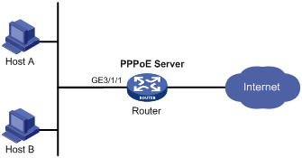
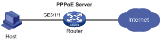
Network configuration
As shown in Figure 3, Host A and Host B run PPPoE client dialup software. The PPPoE server on the router performs local authentication and assigns IP addresses to the clients through a PPP address pool. As a best practice, use a DHCP address pool to assign IP addresses when there are a large number of users.
Procedure
# Create a PPPoE user.
<Router> system-view
[Router] local-user user1 class network
[Router-luser-network-user1] password simple pass1
[Router-luser-network-user1] service-type ppp
[Router-luser-network-user1] quit
# Configure Virtual-Template 1 to use CHAP for authentication. Set the DNS server IP address for the peer.
[Router] interface virtual-template 1
[Router-Virtual-Template1] ppp authentication-mode chap domain dm1
[Router-Virtual-Template1] ppp ipcp dns 8.8.8.8
# Enable PPP accounting.
[Router-Virtual-Template1] ppp account-statistics enable
[Router-Virtual-Template1] quit
# Configure a PPP address pool that contains nine assignable IP addresses, and configure a gateway address for the PPP address pool.
[Router] ip pool pool1 1.1.1.2 1.1.1.10
[Router] ip pool pool1 gateway 1.1.1.1
# Enable the PPPoE server on GigabitEthernet 3/1/1, and bind the interface to Virtual-Template 1.
[Router] interface gigabitethernet 3/1/1
[Router-GigabitEthernet3/1/1] pppoe-server bind virtual-template 1
[Router-GigabitEthernet3/1/1] quit
# In ISP domain dm1, perform local AAA for PPP users and authorize an address pool.
[Router] domain name dm1
[Router-isp-dm1] authentication ppp local
[Router-isp-dm1] accounting ppp local
[Router-isp-dm1] authorization ppp local
[Router-isp-dm1] authorization-attribute ip-pool pool1
[Router-isp-dm1] quit
Verifying the configuration
# Verify that Host A and Host B can access the Internet by using the username user1 and password pass1. (Details not shown.)
Example: Configuring the PPPoE server to assign IPv4 addresses through the local DHCP server
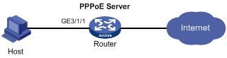
Network configuration
As shown in Figure 4, configure the PPPoE server as a DHCP server to assign an IP address to the host.
Procedure
# Configure Virtual-Template 1 to use PAP for authentication.
<Router> system-view
[Router] interface virtual-template 1
[Router-Virtual-Template1] ppp authentication-mode pap domain dm1
# Enable PPP accounting.
[Router-Virtual-Template1] ppp account-statistics enable
[Router-Virtual-Template1] quit
# Enable the PPPoE server on GigabitEthernet 3/1/1, and bind the interface to Virtual-Template 1.
[Router] interface gigabitethernet 3/1/1
[Router-GigabitEthernet3/1/1] pppoe-server bind virtual-template 1
[Router-GigabitEthernet3/1/1] quit
# Enable DHCP.
[Router] dhcp enable
# Configure DHCP address pool pool1.
[Router] dhcp server ip-pool pool1
[Router-dhcp-pool-pool1] network 1.1.1.0 24 export-route
[Router-dhcp-pool-pool1] gateway-list 1.1.1.1 export-route
[Router-dhcp-pool-pool1] dns-list 8.8.8.8
# Exclude the IP address 1.1.1.1 from dynamic allocation in DHCP address pool pool1.
[Router-dhcp-pool-pool1] forbidden-ip 1.1.1.1
[Router-dhcp-pool-pool1] quit
# Create a PPPoE user.
[Router] local-user user1 class network
[Router-luser-network-user1] password simple pass1
[Router-luser-network-user1] service-type ppp
[Router-luser-network-user1] quit
# In ISP domain dm1, perform local AAA for PPP users and authorize an address pool.
[Router] domain name dm1
[Router-isp-dm1] authentication ppp local
[Router-isp-dm1] accounting ppp local
[Router-isp-dm1] authorization ppp local
[Router-isp-dm1] authorization-attribute ip-pool pool1
[Router-isp-dm1] quit
Verifying the configuration
# Log in to the router by using username user1 and password pass1.
# Display information about IP addresses assigned by the DHCP server.
[Router] display dhcp server ip-in-use
IP address Client identifier/ Lease expiration Type
Hardware address
1.1.1.2 3030-3030-2e30-3030- Unlimited Auto(C)
662e-3030-3033-2d45-
7468-6572-6e65-74
The output shows that the router has assigned an IP address to the host.
Example: Configuring the PPPoE server to assign IPv4 addresses through a remote DHCP server
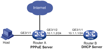
Network configuration
As shown in Figure 5, configure the PPPoE server as a DHCP relay agent to relay an IP address from the DHCP server to the host.
Procedure
1. Configure Router A as the PPPoE server:
# Configure Virtual-Template 1 to use PAP for authentication.
<RouterA> system-view
[RouterA] interface virtual-template 1
[RouterA-Virtual-Template1] ppp authentication-mode pap domain dm1
# Enable PPP accounting.
[RouterA-Virtual-Template1] ppp account-statistics enable
[RouterA-Virtual-Template1] quit
# Enable the PPPoE server on GigabitEthernet 3/1/1, and bind the interface to Virtual-Template 1.
[RouterA] interface gigabitethernet 3/1/1
[RouterA-GigabitEthernet3/1/1] pppoe-server bind virtual-template 1
[RouterA-GigabitEthernet3/1/1] quit
# Enable DHCP.
[RouterA] dhcp enable
# Enable recording of relay entries on the relay agent.
[RouterA] dhcp relay client-information record
# Create DHCP relay address pool pool1.
[RouterA] dhcp server ip-pool pool1
# Specify a gateway address for the clients in pool1.
[RouterA-dhcp-pool-pool1] gateway-list 2.2.2.1 export-route
# Specify a DHCP server for pool1.
[RouterA-dhcp-pool-pool1] remote-server 10.1.1.1
[RouterA-dhcp-pool-pool1] quit
# Specify an IP address for GigabitEthernet 3/1/2.
[RouterA] interface gigabitethernet 3/1/2
[RouterA-GigabitEthernet3/1/2] ip address 10.1.1.2 24
[RouterA-GigabitEthernet3/1/2] quit
# Create a PPPoE user.
[RouterA] local-user user1 class network
[RouterA-luser-network-user1] password simple pass1
[RouterA-luser-network-user1] service-type ppp
[RouterA-luser-network-user1] quit
# In ISP domain dm1, perform local AAA for PPP users and authorize an address pool.
[Router] domain name dm1
[Router-isp-dm1] authentication ppp local
[Router-isp-dm1] accounting ppp local
[Router-isp-dm1] authorization ppp local
[Router-isp-dm1] authorization-attribute ip-pool pool1
[Router-isp-dm1] quit
2. Configure Router B as a DHCP server.
# Enable DHCP.
<RouterB> system-view
[RouterB] dhcp enable
# Create DHCP address pool pool1, and specify a primary subnet and a gateway address for DHCP clients.
[RouterB] dhcp server ip-pool pool1
[RouterB-dhcp-pool-pool1] network 2.2.2.0 24
[RouterB-dhcp-pool-pool1] gateway-list 2.2.2.1
[RouterB-dhcp-pool-pool1] dns-list 8.8.8.8
# Exclude the IP address 2.2.2.1 from dynamic allocation in DHCP address pool pool1.
[RouterB-dhcp-pool-pool1] forbidden-ip 2.2.2.1
[RouterB-dhcp-pool-pool1] quit
# Specify an IP address for GigabitEthernet 3/1/1.
[RouterB] interface gigabitethernet 3/1/1
[RouterB-GigabitEthernet3/1/1] ip address 10.1.1.1 24
[RouterB-GigabitEthernet3/1/1] quit
# Configure a static route to the PPPoE server.
[RouterB] ip route-static 2.2.2.0 24 10.1.1.2
Verifying the configuration
# Log in to Router A by using username user1 and password pass1.
# Display relay entries on the DHCP relay agent on Router A.
[RouterA] display dhcp relay client-information
Total number of client-information items: 1
Total number of dynamic items: 1
Total number of temporary items: 0
IP address MAC address Type Interface VPN name
2.2.2.3 00e0-0000-0001 Dynamic BAS0 N/A
# Display information about the assigned IP addresses on Router B.
[RouterB] display dhcp server ip-in-use
IP address Client identifier/ Lease expiration Type
Hardware address
2.2.2.3 00e0-0000-0001 Nov 14 20:14:26 2017 Auto(C)
The output shows that Router B has assigned an IP address to the host.
Example: Configuring the PPPoE server to assign IPv6 addresses through the IA_NA method (remote DHCP server)
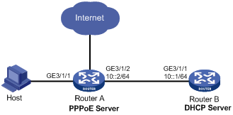
Network configuration
As shown in Figure 6, configure the PPPoE server as a DHCP relay agent to relay an IPv6 address from the DHCP server to the host.
Procedure
1. Configure Router A as the PPPoE server:
# Configure Virtual-Template 1 to use PAP for authentication.
<RouterA> system-view
[RouterA] interface virtual-template 1
[RouterA-Virtual-Template1] ppp authentication-mode pap domain dm1
# Configure Virtual-Template 1 to automatically generate an IPv6 link-local address.
[RouterA-Virtual-Template1] ipv6 address auto link-local
# Disable RA message suppression on Virtual-Template 1.
[RouterA-Virtual-Template1] undo ipv6 nd ra halt
# Set the managed address configuration flag (M) to 1 in RA advertisements to be sent on Virtual-Template 1. Hosts that receive the advertisements will obtain IPv6 addresses through DHCPv6.
[RouterA-Virtual-Template1] ipv6 nd autoconfig managed-address-flag
# Set the other stateful configuration flag (O) to 1 in RA advertisements to be sent on Virtual-Template 1.
[RouterA-Virtual-Template1] ipv6 nd autoconfig other-flag
# Enable the DHCPv6 relay agent and enable recording client information in DHCPv6 relay entries on Virtual-Template 1.
[RouterA-Virtual-Template1] ipv6 dhcp select relay
[RouterA-Virtual-Template1] ipv6 dhcp relay client-information record
# Enable PPP accounting.
[RouterA-Virtual-Template1] ppp account-statistics enable
[RouterA-Virtual-Template1] quit
# Enable the PPPoE server on GigabitEthernet 3/1/1, and bind the interface to Virtual-Template 1.
[RouterA] interface gigabitethernet 3/1/1
[RouterA-GigabitEthernet3/1/1] pppoe-server bind virtual-template 1
[RouterA-GigabitEthernet3/1/1] quit
# Create DHCP relay address pool pool1.
[RouterA] ipv6 dhcp pool pool1
# Specify a gateway address for the clients in pool1.
[RouterA-dhcp6-pool-pool1] gateway-list 3001::1
# Specify a DHCP server for pool1.
[RouterA-dhcp6-pool-pool1] remote-server 10::1
[RouterA-dhcp6-pool-pool1] quit
# Create a PPPoE user.
[RouterA] local-user user1 class network
[RouterA-luser-network-user1] password simple pass1
[RouterA-luser-network-user1] service-type ppp
[RouterA-luser-network-user1] quit
# In ISP domain dm1, perform local AAA for PPP users and authorize an address pool.
[Router] domain name dm1
[Router-isp-dm1] authentication ppp local
[Router-isp-dm1] accounting ppp local
[Router-isp-dm1] authorization ppp local
[RouterA-isp-dm1] authorization-attribute ipv6-pool pool1
[Router-isp-dm1] quit
2. Configure Router B as a DHCP server.
# Create DHCPv6 address pool pool1.
<RouterB> system-view
[RouterB] ipv6 dhcp pool pool1
# Specify primary subnet 3001::/32 for dynamic address allocation in the DHCPv6 address pool.
[RouterB-dhcp6-pool-pool1] network 3001::/32
# Specify DNS server 2001:2::3 in the DHCPv6 address pool.
[RouterB-dhcp6-pool-pool1] dns-server 2001:2::3
[RouterB-dhcp6-pool-pool1] quit
# Exclude the IP address 3001::1 from dynamic allocation in DHCPv6 address pool pool1.
[RouterB] ipv6 dhcp server forbidden-address 3001::1
# Enable the DHCPv6 server on GigabitEthernet 3/1/1.
[RouterB] interface gigabitethernet 3/1/1
[RouterB-GigabitEthernet3/1/1] ipv6 dhcp select server
[RouterB-GigabitEthernet3/1/1] quit
# Configure a static route to specify the next hop as 10::2 (IPv6 address of the interface connected to the DHCPv6 client) for the DHCPv6 replies destined to 3001::/32.
[RouterB] ipv6 route-static 3001:: 32 10::2
Verifying the configuration
# Log in to Router A by using username user1 and password pass1.
# Display PPP user information on GigabitEthernet 3/1/1.
[RouterA] display ppp access-user interface gigabitethernet 3/1/1
Interface MAC address IP address Username
S/C-VLAN IPv6 PDPrefix IPv6 address
BAS0 0000-5e08-9d00 - user1
-/- - 3001::2
The output shows that Router A has assigned a global unicast IPv6 address to the host through DHCPv6.
Example: Configuring the PPPoE server to assign IPv6 addresses through the NDRA method (authorized prefixes)
Network configuration
As shown in Figure 7, configure the PPPoE server to advertise the following information to the host:
· IPv6 prefix in RA messages.
· IPv6 interface identifier during IPv6CP negotiation.
The host uses the IPv6 prefix and IPv6 interface identifier to generate an IPv6 global unicast address. The IPv6 address prefixes in RA packets are authorized prefixes.

Procedure
# Create Virtual-Template 1.
<Router> system-view
[Router] interface virtual-template 1
# Configure Virtual-Template 1 to use PAP to authenticate the peer.
[Router-Virtual-Template1] ppp authentication-mode pap domain dm1
# Configure Virtual-Template 1 to automatically generate an IPv6 link-local address.
[Router-Virtual-Template1] ipv6 address auto link-local
# Enable Virtual-Template 1 to advertise RA messages.
[Router-Virtual-Template1] undo ipv6 nd ra halt
# Set the other stateful configuration flag (O) to 1 in RA advertisements to be sent.
[Router-Virtual-Template1] ipv6 nd autoconfig other-flag
# Enable the DHCPv6 Server on Virtual-Template 1.
[Router-Virtual-Template1] ipv6 dhcp select server
# Enable PPP accounting.
[Router-Virtual-Template1] ppp account-statistics enable
[Router-Virtual-Template1] quit
# Enable the PPPoE sever on GigabitEthernet 3/1/1, and bind the interface to Virtual-Template 1.
[Router] interface gigabitethernet 3/1/1
[Router-GigabitEthernet3/1/1] pppoe-server bind virtual-template 1
[Router-GigabitEthernet3/1/1] quit
# Create a DHCPv6 address pool named pool1 and specify DNS server IPv6 address 2:2::3.
[Router] ipv6 dhcp pool pool1
[Router-dhcp6-pool-pool1] dns-server 2:2::3
[Router-dhcp6-pool-pool1] quit
# Configure a PPPoE user.
[Router] local-user user1 class network
[Router-luser-network-user1] password simple pass1
[Router-luser-network-user1] service-type ppp
[Router-luser-network-user1] quit
# Configure local AAA for the PPP users in the ISP domain dm1.
[Router] domain name dm1
[Router-isp-dm1] authentication ppp local
[Router-isp-dm1] accounting ppp local
[Router-isp-dm1] authorization ppp local
# Configure an IPv6 prefix and a DHCPv6 address pool authorized to the users in the ISP domain dm1.
[Router-isp-dm1] authorization-attribute ipv6-prefix 2003:: 64
[Router-isp-dm1] authorization-attribute ipv6-pool pool1
[Router-isp-dm1] quit
Verifying the configuration
# Display PPP user information on GigabitEthernet 3/1/1.
[Router] display ppp access-user interface gigabitethernet 3/1/1
Interface MAC address IP address Username
S/C-VLAN IPv6 PDPrefix IPv6 address
BAS0 0000-5e08-9d00 - user1
-/- - 2003::9CBC:3898:0:605
Example: Configuring the PPPoE server to assign IPv6 addresses through the NDRA method (one prefix per user)
Network configuration
As shown in Figure 7, configure the PPPoE server to advertise the following information to the host:
· IPv6 prefix in RA messages.
· IPv6 interface identifier during IPv6CP negotiation.
The host uses the IPv6 prefix and IPv6 interface identifier to generate an IPv6 global unicast address. The IPv6 address prefixes in RA packets are authorized prefixes.
Figure 8 Network diagram
Procedure
# Create Virtual-Template 1.
<Router> system-view
[Router] interface virtual-template 1
# Configure Virtual-Template 1 to use PAP to authenticate the peer.
[Router-Virtual-Template1] ppp authentication-mode pap domain dm1
# Configure Virtual-Template 1 to automatically generate an IPv6 link-local address.
[Router-Virtual-Template1] ipv6 address auto link-local
# Enable Virtual-Template 1 to advertise RA messages.
[Router-Virtual-Template1] undo ipv6 nd ra halt
# Enable the DHCPv6 Server on Virtual-Template 1.
[Router-Virtual-Template1] ipv6 dhcp select server
# Enable issuing ND prefix network routes.
[Router-Virtual-Template1] ppp nd-prefix-route enable
# Enable PPP accounting.
[Router-Virtual-Template1] ppp account-statistics enable
[Router-Virtual-Template1] quit
# Enable the PPPoE sever on GigabitEthernet 3/1/1, and bind the interface to Virtual-Template 1.
[Router] interface gigabitethernet 3/1/1
[Router-GigabitEthernet3/1/1] pppoe-server bind virtual-template 1
[Router-GigabitEthernet3/1/1] quit
# Create prefix pool 1, and specify the prefix 2003::/32 with the assigned prefix length 64. Prefix pool 1 contains 4294967296 prefixes from 2003::/64 to 2003:0:FFFF:FFFF::/64.
[Router] ipv6 dhcp prefix-pool 1 prefix 2003::/32 assign-len 64
# Create a DHCPv6 address pool named pool1, and apply prefix pool 1 to the address pool.
[Router] ipv6 dhcp pool pool1
[Router-dhcp6-pool-pool1] prefix-pool 1
[Router-dhcp6-pool-pool1] quit
# Configure a PPPoE user.
[Router] local-user user1 class network
[Router-luser-network-user1] password simple pass1
[Router-luser-network-user1] service-type ppp
[Router-luser-network-user1] quit
# Configure local AAA for the PPP users in the ISP domain dm1.
[Router] domain name dm1
[Router-isp-dm1] authentication ppp local
[Router-isp-dm1] accounting ppp local
[Router-isp-dm1] authorization ppp local
# Authorize ND prefix pool pool1 and the primary DNS server to users in the ISP domain dm1.
[Router-isp-dm1] authorization-attribute ipv6-nd-prefix-pool pool1
[Router-isp-dm1] authorization-attribute primary-dns ipv6 2:2::3
[Router-isp-dm1] quit
Verifying the configuration
# Display PPP user information on GigabitEthernet 3/1/1.
[Router] display ppp access-user interface gigabitethernet 3/1/1
Interface MAC address IP address Username
S/C-VLAN IPv6 PDPrefix IPv6 address
BAS0 0000-5e08-9d00 - user1
-/- - 2003::9CBC:3898:0:605
Example: Configuring the PPPoE server to assign IPv6 addresses through the IA_NA+IA_PD method
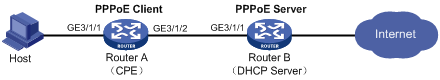
Network configuration
As shown in Figure 9, configure the PPPoE server to assign an IPv6 global unicast address to the CPE WAN interface through IA_NA and assign a prefix to Router A through IA_PD. Router A then assigns the prefix to the host for it to generate an IPv6 address.
Procedure
1. Configure Router B (PPPoE server):
# Create Virtual-Template 1.
<RouterB> system-view
[RouterB] interface virtual-template 1
# Configure Virtual-Template 1 to use PAP to authenticate the peer.
[RouterB-Virtual-Template1] ppp authentication-mode pap domain dm1
# Automatically generate a link-local address for Virtual-Template 1.
[RouterB-Virtual-Template1] ipv6 address auto link-local
# Enable Virtual-Template 1 to advertise RA messages.
[RouterB-Virtual-Template1] undo ipv6 nd ra halt
# Set the managed address configuration flag (M) to 1 in RA advertisements to be sent on Virtual-Template 1. Hosts that receive the advertisements will obtain IPv6 addresses through DHCPv6.
[RouterB-Virtual-Template1] ipv6 nd autoconfig managed-address-flag
# Set the other stateful configuration flag (O) to 1 in RA advertisements to be sent on Virtual-Template 1. Hosts that receive the advertisements will obtain information other than IPv6 address through DHCPv6.
[RouterB-Virtual-Template1] ipv6 nd autoconfig other-flag
# Enable the DHCPv6 server feature.
[RouterB-Virtual-Template1] ipv6 dhcp select server
# Enable PPP accounting.
[RouterB-Virtual-Template1] ppp account-statistics enable
[RouterB-Virtual-Template1] quit
# Enable the PPPoE sever on GigabitEthernet 3/1/1, and bind the interface to Virtual-Template 1.
[RouterB] interface gigabitethernet 3/1/1
[RouterB-GigabitEthernet3/1/1] pppoe-server bind virtual-template 1
[RouterB-GigabitEthernet3/1/1] quit
# Create prefix pool 6, and specify prefix 4001::/32 with assigned prefix length 42.
[RouterB] ipv6 dhcp prefix-pool 6 prefix 4001::/32 assign-len 42
# Create address pool 1, specify IPv6 subnet 3001::/32 for dynamic allocation in the address pool, and apply prefix pool 6 to address pool 1.
[RouterB] ipv6 dhcp pool pool1
[RouterB-dhcp6-pool-pool1] network 3001::/32
[RouterB-dhcp6-pool-pool1] prefix-pool 6
[RouterB-dhcp6-pool-pool1] quit
# Configure a PPPoE user.
[RouterB] local-user user1 class network
[RouterB-luser-network-user1] password simple pass1
[RouterB-luser-network-user1] service-type ppp
[RouterB-luser-network-user1] quit
# In the ISP domain dm1, perform local AAA for PPP users, and authorize an address pool to PPP users.
[Router] domain name dm1
[Router-isp-dm1] authentication ppp local
[Router-isp-dm1] accounting ppp local
[Router-isp-dm1] authorization ppp local
[Router-isp-dm1] authorization-attribute ipv6-pool pool1
[Router-isp-dm1] quit
2. Configure Router A (PPPoE Client):
|
|
NOTE: · The device (Router B in this example) can act as a PPPoE server, and cannot act as a PPPoE client. · The configuration commands for the device acting as the PPPoE client might vary by version. The configuration in this section is an example. For more information about the PPPoE client configuration, see the product manual for the device acting as the PPPoE client. |
# Enable bundle DDR on Dialer 1.
<RouterA> system-view
[RouterA] interface dialer 1
[RouterA-Dialer1] dialer bundle enable
# Assign Dialer 1 to dialer group 1.
[RouterA-Dialer1] dialer-group 1
# Set the local username and password that Router A sends to Router B for PAP authentication on Dialer 1.
[RouterA-Dialer1] ppp pap local-user user1 password simple pass1
# Configure Dialer 1 as a DHCPv6 client to use DHCPv6 for obtaining IPv6 addresses and other network configuration parameters.
[RouterA-Dialer1] ipv6 address dhcp-alloc
# Configure Dialer 1 to use DHCPv6 for obtaining IPv6 prefixes and other network configuration parameters. Specify ID 1 for the obtained IPv6 prefix.
[RouterA-Dialer1] ipv6 dhcp client pd 1
[RouterA-Dialer1] quit
# Establish a PPPoE session and specify dialer bundle 1 corresponding to Dialer 1 for the session.
[RouterA] interface gigabitethernet 3/1/2
[RouterA-GigabitEthernet3/1/2] pppoe-client dial-bundle-number 1
[RouterA-GigabitEthernet3/1/2] quit
# Configure the default route.
[RouterA] ipv6 route-static :: 0 dialer 1
# Configure the PPPoE client to operate in permanent online mode.
[RouterA] interface dialer 1
[RouterA-Dialer1] dialer timer idle 0
# Set the auto-dial timer to 60 seconds on Dialer 1.
[RouterA-Dialer1] dialer timer autodial 60
[RouterA-Dialer1] quit
# Disable RA message suppression on GigabitEthernet 3/1/1.
[RouterA] interface gigabitethernet 3/1/1
[RouterA-GigabitEthernet3/1/1] undo ipv6 nd ra halt
# Configure GigabitEthernet 3/1/1 to generate an IPv6 address by using the prefix with ID 1 and assign the IPv6 prefix with ID 1 to endpoints through RA messages.
[RouterA-GigabitEthernet3/1/1] ipv6 address 1 123::123:1:1/64
[RouterA-GigabitEthernet3/1/1] quit
Verifying the configuration
# Verify that Router B has assigned a prefix to Router A.
[RouterB] display ipv6 dhcp server pd-in-use
Pool: 1
IPv6 prefix Type Lease expiration
4001::/42 Auto(C) Jul 10 19:45:01 2013
Then, Router A can assign the prefix 4001::1/42 to the host who uses the prefix to generate an IPv6 global unicast address.
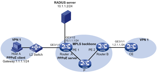
Example: Configuring PPPoE server RADIUS-based IP address assignment
Network configuration
As shown in Figure 10, configure the PPPoE server to meet the following requirements:
· The PPPoE server uses the RADIUS server to perform authentication, authorization, and accounting for access users
· The RADIUS server assigns access users a DHCP address pool named pool1 and a VPN instance named vpn1.
· Users in vpn1 obtain IP addresses from DHCP address pool pool1.
Procedure
1. Configure the MPLS L3VPN feature.
For the two ends of VPN 1 to communicate with each other, specify the same route target attributes on the two PEs (Router A and Router B). This example describes only the authentication-related configuration on the PE that is connected to the PPPoE client. For information about configuring MPLS L3VPN, see MPLS Configuration Guide.
2. Configure the RADIUS server:
This example uses Free RADIUS that runs in the Linux operating system.
# Add the following text to the client.conf file to configure RADIUS client information.
client 10.1.1.1/24 {
secret = radius
}
Where, secret represents the shared key for authentication, authorization, and accounting.
# Add the following text to the users.conf file to configure legal user information.
user1 Auth-Type == CHAP,User-Password := pass1
Service-Type = Framed-User,
Framed-Protocol = PPP,
Framed-Pool = "pool1",
H3C-VPN-Instance = "vpn1",
3. Configure Router A:
a. Configure the PPPoE server:
# Configure Virtual-Template 1 to use CHAP for authentication and use ISP domain dm1 as the authentication domain.
<RouterA> system-view
[RouterA] interface virtual-template 1
[RouterA-Virtual-Template1] ppp authentication-mode chap domain dm1
# Enable PPP accounting.
[RouterA-Virtual-Template1] ppp account-statistics enable
[RouterA-Virtual-Template1] quit
# Enable DHCP.
[RouterA] dhcp enable
# Configure DHCP address pool pool1.
[RouterA] dhcp server ip-pool pool1
[RouterA-dhcp-pool-pool1] vpn-instance vpn1
[RouterA-dhcp-pool-pool1] network 1.1.1.0 24 export-route
[RouterA-dhcp-pool-pool1] gateway-list 1.1.1.1 export-route
[RouterA-dhcp-pool-pool1] dns-list 8.8.8.8
# Exclude IP address 1.1.1.1 from dynamic allocation in the address pool.
[RouterA-dhcp-pool-pool1] forbidden-ip 1.1.1.1
[RouterA-dhcp-pool-pool1] quit
# Enable the PPPoE server on GigabitEthernet 3/1/1, and bind the interface to Virtual-Template 1.
[RouterA] interface gigabitethernet 3/1/1
[RouterA-GigabitEthernet3/1/1] pppoe-server bind virtual-template 1
[RouterA-GigabitEthernet3/1/1] quit
b. Configure a RADIUS scheme:
# Create a RADIUS scheme named rs1, and enter its view.
[RouterA] radius scheme rs1
# Specify the primary authentication server and the primary accounting server.
[RouterA-radius-rs1] primary authentication 10.1.1.2
[RouterA-radius-rs1] primary accounting 10.1.1.2
# Set the shared key for secure communication with the server to radius in plain text.
[RouterA-radius-rs1] key authentication simple radius
[RouterA-radius-rs1] key accounting simple radius
# Exclude domain names in the usernames sent to the RADIUS server.
[RouterA-radius-rs1] user-name-format without-domain
[RouterA-radius-rs1] quit
c. Configure an authentication domain:
# Create an ISP domain named dm1.
[RouterA] domain name dm1
# In ISP domain dm1, perform RADIUS authentication, authorization, and accounting for users based on scheme rs1.
[RouterA-isp-dm1] authentication ppp radius-scheme rs1
[RouterA-isp-dm1] authorization ppp radius-scheme rs1
[RouterA-isp-dm1] accounting ppp radius-scheme rs1
[RouterA-isp-dm1] quit
Verifying the configuration
# Verify that Host A can successfully ping CE. (Details not shown.)
# Display binding information about assigned IP addresses in VPN1.
[RouterA] display dhcp server ip-in-use vpn-instance vpn1
IP address Client identifier/ Lease expiration Type
Hardware address
1.1.1.2 3030-3030-2e30-3030- Unlimited Auto(C)
662e-3030-3033-2d45-
7468-6572-6e65-74