- Table of Contents
-
- 16-BRAS Services Configuration Guide
- 00-Preface
- 01-BRAS services overview
- 02-AAA configuration
- 03-ANCP configuration
- 04-PPP configuration
- 05-ITA configuration
- 06-EDSG configuration
- 07-DHCP configuration
- 08-DHCPv6 configuration
- 09-User profile configuration
- 10-Connection limit configuration
- 11-L2TP configuration
- 12-PPPoE configuration
- 13-Portal configuration
- 14-IPoE configuration
- Related Documents
-
| Title | Size | Download |
|---|---|---|
| 04-PPP configuration | 189.00 KB |
PPP link establishment process
Restoring the default settings for the VT interface
Configuring PPP authentication
Configuring PAP authentication
Configuring CHAP authentication (authenticator name is configured)
Configuring CHAP authentication (authenticator name is not configured)
Configuring MS-CHAP or MS-CHAP-V2 authentication
Configuring the polling feature
Configuring a VT interface not to perform keepalive detection when PPP users have traffic·
Enabling fast reply for keepalive packets
Configuring the PPP negotiation timeout time
Configuring IPv4 address negotiation on the client
Configuring IPv4 address negotiation on the server
Configuring IPv6 address negotiation on the server
Configuring DNS server IP address negotiation on the client
Configuring DNS server IP address negotiation on the server
Configuring magic number check for PPP
Enabling MRU check for PPP packets
Enabling source IP check for PPP users
Configuring the nas-port-type attribute
Suppressing adding PPP peer host routes to the local direct route table
Enabling issuing ND prefix network routes
Configuring the traffic accounting frequency mode for online PPP users
Configuring PPP logging and service tracing objects
Enabling logging for PPP users
Configuring service tracing objects
Display and maintenance commands for PPP
Configuring PPP
PPP in this chapter serves only PPPoE and L2TP applications. For information about PPPoE and L2TP, see BRAS Services Configuration Guide.
About PPP
Point-to-Point Protocol (PPP) is a point-to-point link layer protocol. It provides user authentication, supports synchronous/asynchronous communication, and allows for easy extension.
PPP protocols
PPP includes the following protocols:
· Link control protocol (LCP)—Establishes, tears down, and monitors data links.
· Network control protocol (NCP)—Negotiates the packet format and type for data links.
· Authentication protocols—Authenticate users. Protocols include the following:
¡ Password Authentication Protocol (PAP).
¡ Challenge Handshake Authentication Protocol (CHAP).
¡ Microsoft CHAP (MS-CHAP).
¡ Microsoft CHAP Version 2 (MS-CHAP-V2).
PPP link establishment process
Figure 1 shows the PPP link establishment process.
Figure 1 PPP link establishment process
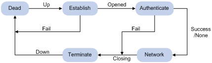
1. Initially, PPP is in Link Dead phase. After the physical layer goes up, PPP enters the Link Establishment phase (Establish).
2. In the Link Establishment phase, the LCP negotiation is performed. The LCP configuration options include Authentication-Protocol, Async-Control-Character-Map (ACCM), Maximum-Receive-Unit (MRU), Magic-Number, Protocol-Field-Compression (PFC), Address-and-Control-Field-Compression (ACFC), and MP.
¡ If the negotiation fails, LCP reports a Fail event, and PPP returns to the Dead phase.
¡ If the negotiation succeeds, LCP enters the Opened state and reports an Up event, indicating that the underlying layer link has been established. At this time, the PPP link is not established for the network layer, and network layer packets cannot be transmitted over the link.
3. If authentication is configured, the PPP link enters the Authentication phase, where PAP, CHAP, MS-CHAP, or MS-CHAP-V2 authentication is performed.
¡ If the client fails to pass the authentication, LCP reports a Fail event and enters the Link Termination phase. In this phase, the link is torn down and LCP goes down.
¡ If the client passes the authentication, LCP reports a Success event.
4. If a network layer protocol is configured, the PPP link enters the Network-Layer Protocol phase for NCP negotiation, such as IPCP negotiation and IPv6CP negotiation.
¡ If the NCP negotiation succeeds, the link goes up and becomes ready to carry negotiated network-layer protocol packets.
¡ If the NCP negotiation fails, NCP reports a Down event and enters the Link Termination phase.
If the interface is configured with an IP address, the IPCP negotiation is performed. IPCP configuration options include IP addresses and DNS server IP addresses. After the IPCP negotiation succeeds, the link can carry IP packets.
5. After the NCP negotiation is performed, the PPP link remains active until either of the following events occurs:
¡ Explicit LCP or NCP frames close the link.
¡ Some external events take place (for example, the intervention of a user).
PPP authentication
PPP supports the following authentication methods:
· PAP—PAP is a two-way handshake authentication protocol using the username and password.
PAP sends username/password pairs in plain text over the network. If authentication packets are intercepted in transit, network security might be threatened. For this reason, it is suitable only for low-security environments.
· CHAP—CHAP is a three-way handshake authentication protocol.
CHAP transmits usernames but not passwords over the network. It transmits the result calculated from the password and random packet ID by using the MD5 algorithm. It is more secure than PAP. The authenticator may or may not be configured with a username. As a best practice, configure a username for the authenticator, which makes it easier for the peer to verify the identity of the authenticator.
· MS-CHAP—MS-CHAP is a three-way handshake authentication protocol.
MS-CHAP differs from CHAP as follows: MS-CHAP provides authentication retry. If the peer fails authentication, it is allowed to retransmit authentication information to the authenticator for reauthentication. The authenticator allows a peer to retransmit a maximum of three times.
· MS-CHAP-V2—MS-CHAP-V2 is a three-way handshake authentication protocol.
MS-CHAP-V2 differs from CHAP as follows:
¡ MS-CHAP-V2 provides two-way authentication by piggybacking a peer challenge on the Response packet and an authenticator response on the Acknowledge packet.
¡ MS-CHAP-V2 supports authentication retry. If the peer fails authentication, it is allowed to retransmit authentication information to the authenticator for reauthentication. The authenticator allows a peer to retransmit a maximum of three times.
¡ MS-CHAP-V2 supports password change. If the peer fails authentication because of an expired password, it will send the new password entered by the user to the authenticator for reauthentication.
PPP for IPv4
On IPv4 networks, PPP negotiates the IP address and DNS server address during IPCP negotiation.
IP address negotiation
IP address negotiation enables one end to assign an IP address to the other.
An interface can act as a client or a server during IP address negotiation:
· Client—Obtains an IP address from the server. Use the client mode when the device accesses the Internet through an ISP.
· Server—Assigns an IP address to the client. Before you configure the IP address of the server, you must perform one of the following tasks:
¡ Configure a local address pool and associate the pool with the ISP domain.
¡ Specify an IP address or an address pool for the client on the interface.
When IP address negotiation is enabled on a client, the server selects an IP address for the client in the following sequence:
1. If the AAA server configures an IP address or address pool for the client, the server selects that IP address or an IP address from the pool. The IP address or address pool is configured on the AAA server instead of the PPP server. For information about AAA, see AAA configuration in BRAS Services Configuration Guide.
2. If an address pool is associated with the ISP domain used during client authentication, the server selects an IP address from the pool.
3. If an IP address or address pool is specified for the client on the interface of the server, the server selects that IP address or an IP address from that pool.
DNS server address negotiation
IPCP negotiation can determine the DNS server IP address.
When the device is connected to a host, configure the device as the server to assign the DNS server IP address to the host.
When the device is connected to an ISP access server, configure the device as the client. Then, the device can obtain the DNS server IP address from the ISP access server.
PPP for IPv6
On IPv6 networks, PPP negotiates only the IPv6 interface identifier instead of the IPv6 address and IPv6 DNS server address during IPv6CP negotiation. All authentication users have to obtain IPv6 global unicast addresses and IPv6 DNS server addresses by using ND or DHCPv6 protocols.
IPv6 address assignment
A host can get an IPv6 global unicast address through the following methods:
· NDRA—The host obtains an IPv6 prefix in an RA message. The host then generates an IPv6 global unicast address by combining the IPv6 prefix and the negotiated IPv6 interface identifier. The IPv6 prefix in the RA message is determined in the following sequence:
¡ IPv6 prefix authorized by AAA.
¡ Prefix in the ND prefix pool authorized by AAA.
¡ RA prefix configured on the interface.
¡ Prefix of the IPv6 global unicast address configured on the interface.
The ND prefix pool authorized by AAA and the IA_NA method are mutually exclusive. For information about the ND protocol, see DHCPv6 configuration in BRAS Services Configuration Guide.
· DHCPv6 (IA_NA)—The host requests an IPv6 global unicast address through DHCPv6. The server assigns an IPv6 address to the host from the address pool authorized by AAA. If no AAA-authorized address pool exists, DHCPv6 uses the address pool that matches the server's IPv6 address to assign an IPv6 address to the host. For information about DHCPv6, see DHCPv6 configuration in BRAS Services Configuration Guide.
· DHCPv6 (IA_PD)—A client-side device requests prefixes through DHCPv6 and assigns them to downstream hosts. The hosts then use the prefixes to generate global IPv6 addresses. This method uses the same principle of selecting address pools as the DHCPv6 (IA_NA) method.
The device can assign a host an IPv6 address in either of the following ways:
· When the host connects to the device directly or through a bridge device, the device can use the NDRA method or the IA_NA method.
· When the host accesses the device through a router, the device can use the IA_PD method to assign an IPv6 prefix to the router. The router assigns the prefix to the host to generate an IPv6 global unicast address.
IPv6 DNS server address assignment
On IPv6 networks, two methods are available for the IPv6 DNS server address assignment:
· AAA authorizes the IPv6 DNS server address and assigns this address to the host through RA messages.
· The DHCPv6 client requests an IPv6 DNS server address from the DHCPv6 server.
Protocols and standards
RFC 1661: The Point-to-Point Protocol (PPP)
PPP tasks at a glance
To configure PPP, perform the following tasks:
¡ Restoring the default settings for the VT interface
In PPPoE and L2TP application environments, you must configure VT interfaces. For information about PPPoE and L2TP, see PPPoE configuration and L2TP configuration in BRAS Services Configuration Guide.
2. Configuring PPP authentication
Choose one of the following tasks:
¡ Configuring PAP authentication
¡ Configuring CHAP authentication (authenticator name is configured)
¡ Configuring CHAP authentication (authenticator name is not configured)
¡ Configuring MS-CHAP or MS-CHAP-V2 authentication
Configure PPP authentication for high-security environments.
3. (Optional.) Configuring the polling feature
4. (Optional.) Configuring a VT interface not to perform keepalive detection when PPP users have traffic
5. (Optional.) Enabling fast reply for keepalive packets
6. (Optional.) Configuring PPP negotiation
¡ Configuring the PPP negotiation timeout time
¡ Configuring IPv4 address negotiation on the client
¡ Configuring IPv4 address negotiation on the server
¡ Configuring IPv6 address negotiation on the server
¡ Configuring DNS server IP address negotiation on the client
¡ Configuring DNS server IP address negotiation on the server
7. (Optional.) Configuring magic number check for PPP
8. (Optional.) Enabling MRU check for PPP packets
9. (Optional.) Specifying that PPP users cannot come online successfully if the online requests do not carry usernames
10. (Optional.) Enabling source IP check for PPP users
11. (Optional.) Enabling PPP user blocking
12. (Optional.) Configuring the nas-port-type attribute
13. (Optional.) Suppressing adding PPP peer host routes to the local direct route table
14. (Optional.) Enabling issuing ND prefix network routes
15. (Optional.) Configuring PPP accounting
¡ Configuring the traffic accounting frequency mode for online PPP users
16. (Optional.) Configuring PPP logging and service tracing objects
¡ Enabling logging for PPP users
¡ Configuring service tracing objects
Configuring a VT interface
Creating a VT interface
About VT interfaces
Virtual-template (VT) interfaces are logical interfaces manually created on devices. A VT interface can implement the functionality of a physical WAN interface with PPP encapsulation enabled. For a VT interface to work properly, you must bind it to a physical interface.
In PPPoE and L2TP applications, you can use VT interfaces to implement related functions of PPP. For more information about PPPoE and L2TP, see PPPoE configuration and L2TP configuration in BRAS Services Configuration Guide.
Restrictions and guidelines
VT interfaces are available only in standard mode. For more information about system operating modes, see device management in Fundamentals Configuration Guide.
Procedure
1. Enter system view.
system-view
2. Create a VT interface and enter its view.
interface virtual-template number
3. (Optional.) Set the interface description.
description text
By default, the description of a VT interface is interface name Interface, for example, Virtual-Template1 Interface.
4. (Optional.) Set the MTU size of the interface.
mtu size
The default setting varies by card model.
5. (Optional.) Set the expected bandwidth of the VT interface.
bandwidth bandwidth-value
By default, the expected bandwidth (in kbps) is the interface baud rate divided by 1000.
Restoring the default settings for the VT interface
Restrictions and guidelines
The default command might interrupt ongoing network services. Make sure you are fully aware of the impact of this command when you execute it on a live network.
The default command might fail to restore the default settings for some commands for reasons such as command dependencies or system restrictions. Use the display this command in interface view to identify these commands. Use the undo forms of these commands or follow the command reference to individually restore their default settings. If your restoration attempt still fails, follow the error message instructions to resolve the problem.
Procedure
1. Enter system view.
system-view
2. Enter VT interface view.
interface virtual-template number
3. Restore the default settings for the interface.
default
Configuring PPP authentication
About PPP authentication
You can configure several authentication modes simultaneously. In LCP negotiation, the authenticator negotiates with the peer in the sequence of configured authentication modes until the LCP negotiation succeeds. If the response packet from the peer carries a recommended authentication mode, the authenticator directly uses the authentication mode if it finds the mode configured.
Configuring PAP authentication
Restrictions and guidelines for PAP authentication
For local AAA authentication, the username and password of the peer must be configured on the authenticator.
For remote AAA authentication, the username and password of the peer must be configured on the remote AAA server.
The username and password configured for the peer must be the same as those configured on the peer by using the ppp pap local-user command.
Configuring the authenticator
1. Enter system view.
system-view
2. Enter interface view.
interface interface-type interface-number
3. Configure the authenticator to authenticate the peer by using PAP.
ppp authentication-mode pap [ domain { isp-name | default enable isp-name } ]
By default, PPP authentication is disabled.
4. Configure local or remote AAA authentication.
For more information about AAA authentication, see AAA configuration in BRAS Services Configuration Guide.
Configuring the peer
1. Enter system view.
system-view
2. Enter interface view.
interface interface-type interface-number
3. Configure the PAP username and password sent from the peer to the authenticator when the peer is authenticated by the authenticator by using PAP.
ppp pap local-user username password { cipher | simple } string
By default, when being authenticated by the authenticator by using PAP, the peer sends null username and password to the authenticator.
For security purposes, the password specified in plaintext form and ciphertext form will be stored in encrypted form.
Configuring CHAP authentication (authenticator name is configured)
Restrictions and guidelines for CHAP authentication (authenticator name is configured)
When you configure the authenticator, follow these guidelines:
· For local AAA authentication, the username and password of the peer must be configured on the authenticator.
· For remote AAA authentication, the username and password of the peer must be configured on the remote AAA server.
· The username and password configured for the peer must meet the following requirements:
¡ The username configured for the peer must be the same as that configured on the peer by using the ppp chap user command.
¡ The passwords configured for the authenticator and peer must be the same.
When you configure the peer, follow these guidelines:
· For local AAA authentication, the username and password of the authenticator must be configured on the peer.
· For remote AAA authentication, the username and password of the authenticator must be configured on the remote AAA server.
· The username and password configured for the authenticator must meet the following requirements:
¡ The username configured for the authenticator must be the same as that configured on the authenticator by using the ppp chap user command.
¡ The passwords configured for the authenticator and peer must be the same.
· The peer does not support the CHAP authentication password configured by using the ppp chap password command. CHAP authentication (authenticator name is configured) will apply even if the authentication name is configured.
Configuring the authenticator
1. Enter system view.
system-view
2. Enter interface view.
interface interface-type interface-number
3. Configure the authenticator to authenticate the peer by using CHAP.
ppp authentication-mode chap [ domain { isp-name | default enable isp-name } ]
By default, PPP authentication is disabled.
4. Configure a username for the CHAP authenticator.
ppp chap user username
The default setting is null.
5. Configure local or remote AAA authentication.
For more information about AAA authentication, see AAA configuration in BRAS Services Configuration Guide.
Configuring the peer
1. Enter system view.
system-view
2. Enter interface view.
interface interface-type interface-number
3. Configure a username for the CHAP peer.
ppp chap user username
The default setting is null.
4. Configure local or remote AAA authentication.
For more information about AAA authentication, see AAA configuration in BRAS Services Configuration Guide.
Configuring CHAP authentication (authenticator name is not configured)
Restrictions and guidelines for CHAP authentication (authenticator name is not configured)
For local AAA authentication, the username and password of the peer must be configured on the authenticator.
For remote AAA authentication, the username and password of the peer must be configured on the remote AAA server.
The username and password configured for the peer must meet the following requirements:
· The username configured for the peer must be the same as that configured on the peer by using the ppp chap user command.
· The password configured for the peer must be the same as that configured on the peer by using the ppp chap password command.
Configuring the authenticator
1. Enter system view.
system-view
2. Enter interface view.
interface interface-type interface-number
3. Configure the authenticator to authenticate the peer by using CHAP.
ppp authentication-mode chap [ domain { isp-name | default enable isp-name } ]
By default, PPP authentication is disabled.
4. Configure local or remote AAA authentication.
For more information about AAA authentication, see AAA configuration in BRAS Services Configuration Guide.
Configuring the peer
1. Enter system view.
system-view
2. Enter interface view.
interface interface-type interface-number
3. Configure a username for the CHAP peer.
ppp chap user username
The default setting is null.
4. Set the CHAP authentication password.
ppp chap password { cipher | simple } string
The default setting is null.
For security purposes, the password specified in plaintext form and ciphertext form will be stored in encrypted form.
Configuring MS-CHAP or MS-CHAP-V2 authentication
Restrictions and guidelines for MS-CHAP or MS-CHAP-V2 authentication
The device can only act as an authenticator for MS-CHAP or MS-CHAP-V2 authentication.
L2TP supports only MS-CHAP authentication.
MS-CHAP-V2 authentication supports password change only when using RADIUS.
As a best practice, do not set the authentication method for PPP users to none when MS-CHAP-V2 authentication is used.
For local AAA authentication, the username and password of the peer must be configured on the authenticator. For remote AAA authentication, the username and password of the peer must be configured on the remote AAA server. The username and password of the peer configured on the authenticator or remote AAA server must be the same as those configured on the peer.
If authentication name is configured, the username configured for the authenticator on the peer must be the same as that configured on the authenticator by using the ppp chap user command.
Configuring MS-CHAP or MS-CHAP-V2 authentication (authenticator name is configured)
1. Enter system view.
system-view
2. Enter interface view.
interface interface-type interface-number
3. Configure the authenticator to authenticate the peer by using MS-CHAP or MS-CHAP-V2.
ppp authentication-mode { ms-chap | ms-chap-v2 } [ domain { isp-name | default enable isp-name } ]
By default, PPP authentication is disabled.
4. Configure a username for the MS-CHAP or MS-CHAP-V2 authenticator.
ppp chap user username
5. Configure local or remote AAA authentication.
For more information about AAA authentication, see AAA configuration in BRAS Services Configuration Guide.
Configuring MS-CHAP or MS-CHAP-V2 authentication (authenticator name is not configured)
1. Enter system view.
system-view
2. Enter interface view.
interface interface-type interface-number
3. Configure the authenticator to authenticate the peer by using MS-CHAP or MS-CHAP-V2.
ppp authentication-mode { ms-chap | ms-chap-v2 } [ domain { isp-name | default enable isp-name } ]
By default, PPP authentication is disabled.
4. Configure local or remote AAA authentication.
For more information about AAA authentication, see AAA configuration in BRAS Services Configuration Guide.
Configuring the polling feature
About the polling feature
The polling feature checks PPP link state.
On an interface that uses PPP encapsulation, the link layer sends keepalive packets at keepalive intervals to detect the availability of the peer. If the interface receives no response to keepalive packets when the keepalive retry limit is reached, it determines that the link fails and reports a link layer down event.
To set the keepalive retry limit, use the timer-hold retry command.
The value 0 disables an interface from sending keepalive packets. In this case, the interface can respond to keepalive packets from the peer.
Restrictions and guidelines
On a slow link, increase the keepalive interval to prevent false shutdown of the interface. This situation might occur when keepalive packets are delayed because a large packet is being transmitted on the link.
The keepalive interval must be smaller than the negotiation timeout time.
Procedure
1. Enter system view.
system-view
2. Enter interface view.
interface interface-type interface-number
3. Set the keepalive interval.
timer-hold seconds
The default setting is 60 seconds for VT interfaces.
4. Set the keepalive retry limit.
timer-hold retry retries
The default setting is 3 for VT interfaces.
Configuring a VT interface not to perform keepalive detection when PPP users have traffic
About configuring a VT interface not to perform keepalive detection when PPP users have traffic
If the configured keepalive interval (timer-hold seconds) or keepalive retry limit (timer-hold retry retries) is small, users might go offline because the interface cannot receive keepalive packets from the peer when congestion occurs in the network. To prevent keepalive packets from making the congestion deteriorate or causing users to frequently go offline, configure the ppp keepalive datacheck command.
With this feature configured, if the user traffic is updated within a keepalive interval, the keepalive timer is reset and delayed by 60 seconds. Therefore, keepalive packets are sent only when user traffic is not updated. For example, suppose you set the keepalive interval to 10 seconds by using the timer-hold command. If user traffic is updated at the 5th second, the keepalive timer is reset and delayed by 60 seconds, which is equivalent to setting the keepalive interval to 70 seconds. In this way, the sending of keepalive packets is delayed. If traffic is updated within the 70 seconds, the keepalive timer is reset and delayed by 60 seconds.
Procedure
1. Enter system view.
system-view
2. Enter VT interface view.
interface virtual-template number
3. Configure the VT interface not to perform keepalive detection when PPP users have traffic.
ppp keepalive datacheck
By default, keepalive packets are sent to detect online users after the keepalive interval expires no matter whether the user traffic is updated within a keepalive interval.
Enabling fast reply for keepalive packets
About fast reply for keepalive packets
This feature allows the hardware to automatically identify and reply to incoming keepalive requests, which can prevent DDoS attacks.
Restrictions and guidelines
This feature is available only on CSPEX (except CSPEX-1204 and CSPEX-1104-E) and CEPC cards and can fast reply to only incoming keepalive requests on Ethernet links.
Procedure
1. Enter system view.
system-view
2. Enable fast reply for keepalive packets.
In standalone mode:
ppp keepalive fast-reply enable slot slot-number
In IRF mode:
ppp keepalive fast-reply enable chassis chassis-number slot slot-number
By default, fast reply is enabled for keepalive packets.
Configuring PPP negotiation
Configuring the PPP negotiation timeout time
About PPP negotiation timeout time
The device starts the PPP negotiation timeout timer after sending a packet. If no response is received before the timer expires, the device sends the packet again.
Restrictions and guidelines
If two ends of a PPP link vary greatly in the LCP negotiation packet processing rate, configure the delay timer on the end with a higher processing rate. The LCP negotiation delay timer prevents frequent LCP negotiation packet retransmission. After the physical layer comes up, PPP starts LCP negotiation when the delay timer expires. If PPP receives LCP negotiation packets before the delay timer expires, it starts LCP negotiation immediately.
Procedure
1. Enter system view.
system-view
2. Enter interface view.
interface interface-type interface-number
3. (Optional.) Configure the LCP negotiation delay timer.
ppp lcp delay milliseconds
By default, PPP starts LCP negotiation after the physical layer comes up.
4. Configure the negotiation timeout time.
ppp timer negotiate seconds
The default setting is 3 seconds.
Configuring IPv4 address negotiation on the client
1. Enter system view.
system-view
2. Enter interface view.
interface interface-type interface-number
3. Enable IP address negotiation.
ip address ppp-negotiate
By default, IP address negotiation is not enabled.
If you execute this command and the ip address command multiple times, the most recent configuration takes effect. For more information about the ip address command, see Layer 3—IP Services Command Reference.
Configuring IPv4 address negotiation on the server
About IP address negotiation on the server
Configure the server to assign an IP address to a client by using the following methods:
· Method 1: Specify an IP address for the client on the server interface.
· Method 2: Specify a PPP or DHCP address pool on the server interface.
· Method 3: Associate a PPP or DHCP address pool with an ISP domain.
· Method 4: Authorize an IP address to a client by using the AAA server.
Restrictions and guidelines for IP address negotiation on the server
For clients requiring no authentication, you can use either method 1 or method 2. When both method 1 and method 2 are configured, the most recent configuration takes effect.
For clients requiring authentication, you can use one or more of the four methods. When multiple methods are configured, method 4 takes precedence over method 3, and method 3 takes precedence over method 1 or method 2. When both method 1 and method 2 are configured, the most recent configuration takes effect.
When you use method 4, enable DHCP on the AAA server by using the dhcp enable command and authorize an IP address to the client. For more information about the dhcp enable command, see DHCP commands in BRAS Services Command Reference.
PPP supports IP address assignment from a PPP or DHCP address pool. If you use a pool name that identifies both a PPP address pool and a DHCP address pool, the system uses the PPP address pool.
When assigning IP address to users through a PPP address pool, make sure the PPP address pool excludes the gateway IP address of the PPP address pool.
Specifying an IP address for the client on the server interface
1. Enter system view.
system-view
2. Enter interface view.
interface interface-type interface-number
3. Configure the interface to assign an IP address to the peer.
remote address ip-address
By default, an interface does not assign an IP address to the peer.
4. Configure an IP address for the interface.
ip address ip-address
By default, no IP address is configured on an interface.
Specifying a PPP address pool on the server interface
1. Enter system view.
system-view
2. Configure a PPP address pool.
ip pool pool-name start-ip-address [ end-ip-address ] [ group group-name ]
3. (Optional.) Enable new IP address assignment.
ip pool pool-name allocate-new-ip enable
By default, new IP address assignment is disabled.
4. (Optional.) Configure a gateway address for the PPP address pool.
ip pool pool-name gateway ip-address [ vpn-instance vpn-instance-name ]
By default, the PPP address pool is not configured with a gateway address.
5. (Optional.) Configure a PPP address pool route.
ppp ip-pool route ip-address { mask-length | mask } [ vpn-instance vpn-instance-name ]
By default, no PPP address pool route exists.
The destination network of the PPP address pool route must include the PPP address pool.
6. Enter interface view.
interface interface-type interface-number
7. Configure the interface to assign an IP address from the configured PPP address pool to the peer.
remote address pool pool-name
By default, an interface does not assign an IP address to the peer.
8. Configure an IP address for the interface.
ip address ip-address
By default, no IP address is configured on an interface.
Specifying a DHCP address pool on the server interface
1. Enter system view.
system-view
2. Configure DHCP.
¡ If the server acts as a DHCP server, perform the following tasks:
- Configure the DHCP server.
- Configure a DHCP address pool on the server.
¡ If the server acts as a DHCP relay agent, perform the following tasks:
- Configure the DHCP relay agent on the server.
- Configure a DHCP address pool on the remote DHCP server.
- Enable the DHCP relay agent to record relay entries.
- Configure a DHCP relay address pool.
For information about configuring a DHCP server and a DHCP relay agent, see BRAS Services Configuration Guide.
3. Enter interface view.
interface interface-type interface-number
4. Configure the interface to assign an IP address from the configured DHCP address pool to the peer.
remote address pool pool-name
By default, an interface does not assign an IP address to the peer.
5. (Optional.) Configure the method of generating DHCP client IDs when PPP users act as DHCP clients.
remote address dhcp client-identifier { { callingnum | username } [ session-info ] | session-info }
By default, the method of generating DHCP client IDs when PPP users act as DHCP clients is not configured.
When DHCP client IDs are generated based on PPP usernames, make sure different users use different PPP usernames to come online.
6. Configure an IP address for the interface.
ip address ip-address
By default, no IP address is configured on an interface.
Associating a PPP address pool with an ISP domain
1. Enter system view.
system-view
2. Configure a PPP address pool.
ip pool pool-name start-ip-address [ end-ip-address ] [ group group-name ]
By default, no PPP address pool is configured.
3. (Optional.) Enable new IP address allocation.
ip pool pool-name allocate-new-ip enable
By default, new IP address allocation is disabled.
4. (Optional.) Configure a gateway address for the PPP address pool.
ip pool pool-name gateway ip-address [ vpn-instance vpn-instance-name ]
By default, the PPP address pool is not configured with a gateway address.
5. (Optional.) Configure a PPP address pool route.
ppp ip-pool route ip-address { mask-length | mask } [ vpn-instance vpn-instance-name ]
By default, no PPP address pool route exists.
The destination network of the PPP address pool route must include the PPP address pool.
6. Enter ISP domain view.
domain name isp-name
7. Associate the ISP domain with the configured PPP address pool for address assignment.
authorization-attribute ip-pool pool-name
By default, no PPP address pool is associated.
For more information about this command, see AAA commands in BRAS Services Command Reference.
8. Return to system view.
quit
9. Enter interface view.
interface interface-type interface-number
10. Configure an IP address for the interface.
ip address ip-address
By default, no IP address is configured on an interface.
Associating a DHCP address pool with an ISP domain
1. Enter system view.
system-view
2. Configure DHCP.
¡ If the server acts as a DHCP server, perform the following tasks:
- Configure the DHCP server.
- Configure a DHCP address pool on the server.
¡ If the server acts as a DHCP relay agent, perform the following tasks:
- Configure the DHCP relay agent on the server.
- Configure a DHCP address pool on the remote DHCP server.
- Enable the DHCP relay agent to record relay entries.
- Configure a DHCP relay address pool.
For information about configuring a DHCP server and a DHCP relay agent, see BRAS Services Configuration Guide.
3. Enter ISP domain view.
domain name isp-name
4. Associate the ISP domain with the configured DHCP address pool or DHCP relay address pool for address assignment.
authorization-attribute ip-pool pool-name
By default, no DHCP address pool or DHCP relay address pool is associated.
For more information about this command, see AAA commands in BRAS Services Command Reference.
5. Return to system view.
quit
6. Enter interface view.
interface interface-type interface-number
7. (Optional.) Configure the method of generating DHCP client IDs when PPP users act as DHCP clients.
remote address dhcp client-identifier { { callingnum | username } [ session-info ] | session-info }
By default, the method of generating DHCP client IDs when PPP users act as DHCP clients is not configured.
When DHCP client IDs are generated based on PPP usernames, make sure different users use different PPP usernames to come online.
8. Configure an IP address for the interface.
ip address ip-address
By default, no IP address is configured on an interface.
Configuring IPv6 address negotiation on the server
Assigning an IPv6 address by using the NDRA method
1. Enter interface view.
interface interface-type interface-number
2. Configure the interface to automatically generate a link-local address.
ipv6 address auto link-local
3. Configure the prefix information in RA messages on the interface.
ipv6 nd ra prefix { ipv6-prefix prefix-length | ipv6-prefix/prefix-length } [ valid-lifetime preferred-lifetime [ no-autoconfig | off-link ] * ]
The IPv6 prefix in the RA message is determined in the following sequence:
¡ IPv6 prefix authorized by AAA.
¡ Prefix in the ND prefix pool authorized by AAA.
¡ RA prefix configured on the interface.
¡ Prefix of the IPv6 global unicast address configured on the interface.
4. Disable RA message suppression on the interface.
undo ipv6 nd ra halt
5. Set the other stateful configuration flag (O) to 1 in RA advertisements to be sent.
ipv6 nd autoconfig other-flag
6. Enable the DHCPv6 server.
ipv6 dhcp select server
7. Return to system view.
quit
8. (Optional.) Configure a PPP IPv6 address network route.
ppp ipv6 route prefix/prefix-length [ vpn-instance vpn-instance-name ] [ preference preference | tag tag ] *
By default, no PPP IPv6 address network route is configured.
9. Create an ISP domain and enter its view.
domain name isp-name
10. Configure an IPv6 prefix authorized to the user in the ISP domain.
authorization-attribute ipv6-prefix ipv6-prefix prefix-length
Assigning an IPv6 address by using the IA_NA method
1. Enter interface view.
interface interface-type interface-number
2. Configure the interface to automatically generate a link-local address.
ipv6 address auto link-local
3. Configure the prefix information in RA messages on the interface.
ipv6 nd ra prefix { ipv6-prefix prefix-length | ipv6-prefix/prefix-length } [ valid-lifetime preferred-lifetime [ no-autoconfig | off-link ] * ]
The IPv6 prefix in the RA message is determined in the following sequence:
¡ IPv6 prefix authorized by AAA.
¡ Prefix in the ND prefix pool authorized by AAA.
¡ RA prefix configured on the interface.
¡ Prefix of the IPv6 global unicast address configured on the interface.
4. Disable RA message suppression on the interface.
undo ipv6 nd ra halt
5. Set the managed address configuration flag (M) to 1 in RA advertisements to be sent.
ipv6 nd autoconfig managed-address-flag
6. Set the other stateful configuration flag (O) to 1 in RA advertisements to be sent.
ipv6 nd autoconfig other-flag
7. Enable the DHCPv6 server.
ipv6 dhcp select server
8. Return to system view.
quit
9. Configure a DHCPv6 address pool and configure an ISP domain to authorize the address pool to users.
For more information, see DHCPv6 configuration and AAA configuration in BRAS Services Configuration Guide.
Assigning an IPv6 address by using the IA_PD method
1. Enter interface view.
interface interface-type interface-number
2. Configure the interface to automatically generate a link-local address.
ipv6 address auto link-local
3. Disable RA message suppression on the interface.
undo ipv6 nd ra halt
4. Enable the DHCPv6 server.
ipv6 dhcp select server
5. Return to system view.
quit
6. Create a prefix pool and specify the prefix and the assigned prefix length for the pool.
ipv6 dhcp prefix-pool prefix-pool-number prefix prefix/prefix-len assign-len assign-len
7. Create a DHCPv6 address pool and enter its view.
ipv6 dhcp pool pool-name
8. Apply a prefix pool to the DHCPv6 address pool, so the DHCPv6 server can dynamically select a prefix from the prefix pool for the client.
prefix-pool prefix-pool-number [ preferred-lifetime preferred-lifetime valid-lifetime valid-lifetime ]
9. Return to system view.
quit
10. Create an ISP domain and enter its view.
domain name isp-name
11. Configure the user authorization attribute in the ISP domain.
authorization-attribute ipv6-pool pool-name
Enabling IP segment match
About IP segment match
This feature enables the local interface to check whether its IP address and the IP address of the remote interface are in the same network segment. If they are not, IPCP negotiation fails.
Procedure
1. Enter system view.
system-view
2. Enter interface view.
interface interface-type interface-number
3. Enable IP segment match.
ppp ipcp remote-address match
By default, this feature is disabled.
Configuring DNS server IP address negotiation on the client
About DNS server IP address negotiation on the client
During PPP negotiation, the server will assign a DNS server IP address only for a client configured with the ppp ipcp dns request command. For some special devices to forcibly assign DNS server IP addresses to clients that do not initiate requests, configure the ppp ipcp dns admit-any command on these devices.
Procedure
1. Enter system view.
system-view
2. Enter interface view.
interface interface-type interface-number
3. Enable the device to request the peer for a DNS server IP address.
ppp ipcp dns request
By default, a client does not request its peer for a DNS server IP address.
4. Configure the device to accept the DNS server IP addresses assigned by the peer even though it does not request the peer for the DNS server IP addresses.
ppp ipcp dns admit-any
By default, a device does not accept the DNS server IP addresses assigned by the peer if it does not request the peer for the DNS server IP addresses.
This command is not necessary if the ppp ipcp dns request command is configured.
Configuring DNS server IP address negotiation on the server
1. Enter system view.
system-view
2. Enter interface view.
interface interface-type interface-number
3. Specify the primary and secondary DNS server IP addresses to be allocated to the peer in PPP negotiation.
ppp ipcp dns primary-dns-address [ secondary-dns-address ]
By default, a device does not allocate DNS server IP addresses to its peer if the peer does not request them.
After this command is configured, the server allocate DNS server IP addresses to a client that initiates requests.
Configuring magic number check for PPP
About magic number check for PPP
In the PPP link establishment process, the magic number is negotiated. After the negotiation, both the local end and the peer end save their magic numbers locally.
The local end sends Echo-Request packets carrying its own magic number. When magic number check is enabled on both the local end and the peer end, the peer end will compare its own magic number with the magic number in the received Echo-Request packets. If they are the same, the link status is considered as normal, and the peer end replies with Echo-Reply packets carrying its own magic number. The local end also compares its own magic number with the magic number carried in the received Echo-Reply packets.
On either end, the link is disconnected and LCP negotiation is restarted in any of the following conditions:
· When fast reply for keepalive packets is enabled:
¡ The magic number check fails for five Echo-Request packets in total.
¡ The magic number check fails for five consecutive Echo-Reply packets.
· When fast reply for keepalive packets is disabled:
¡ The magic number check fails for five consecutive Echo-Request packets.
¡ The magic number check fails for five consecutive Echo-Reply packets.
Only the end with magic number check enabled can check the magic number in received Echo-Request or Echo-Reply packets.
Procedure
1. Enter system view.
system-view
2. Enter interface view.
interface interface-type interface-number
3. Enable magic number check for PPP.
ppp magic-number-check
By default, magic number check is disabled for PPP.
Enabling MRU check for PPP packets
About MRU check for PPP packets
In PPP Link Establishment phase, the Maximum-Receive-Unit (MRU) value is negotiated in the LCP negotiation. When the MTUs of interfaces on the two end of a link are different, PPP uses the smaller MTU as the link MTU.
By default, the device does not perform MRU check if the MTU in a received PPP packet is larger than the negotiated MRU. With MRU check enabled, the device discards a received PPP packet if the MTU in the packet is larger than the negotiated MRU.
Restrictions and guidelines
As a best practice to enhance system security, enable MRU check. Otherwise, a fake peer might attack the device by sending a large number of PPP packets with MTUs larger than the negotiated MRU.
Procedure
1. Enter system view.
system-view
2. Enable MRU check for PPP packets.
ppp mru-check enable
By default, MRU check for PPP packets is disabled.
Specifying that PPP users cannot come online successfully if the online requests do not carry usernames
About specifying that PPP users cannot come online successfully if the online requests do not carry usernames
The username format is userid@isp-name. A username is considered as empty when both the user ID and ISP domain name are empty. If the user ID is empty but the ISP domain name is not empty, the username is considered as non-empty.
By default, when PPP user online requests do not carry the usernames (the usernames are empty), the following rules apply:
· For PPPoE users, the user MAC addresses in the requests are used as the usernames.
· For L2TP users, the calling numbers in the requests are used as the usernames.
If the network environment needs strictly checking the username validity, you can configure this feature. With this feature configured, when the device receives online requests without usernames from PPPoE or L2TP users, the device does not use the user MAC addresses or calling numbers in the requests as usernames for AAA authentication, and the device directly returns authentication failure to users.
Restrictions and guidelines
When the device uses the user MAC addresses or calling numbers in the requests as the usernames for AAA authentication, neither the contents nor the format of the information will be modified.
Procedure
1. Enter system view.
system-view
2. Enter VT interface view.
interface virtual-template number
3. Specify that PPP users cannot come online successfully if the online requests do not carry usernames on the VT interface.
ppp username check
By default, PPP users can come online successfully if the online requests do not carry usernames.
Enabling source IP check for PPP users
About source IP check for PPP users
By default, if a matching PPP user can be queried based on a received PPP packet, the PPP packet is considered as valid and sent to the CPU for processing.
In a low-security environment, attackers might forge a large number of PPP packets from valid PPP users and send them to the device. As a result, a large number of system resources are occupied or even exhausted, and packets from valid PPP users cannot be timely processed.
To avoid such malicious attacks, you can enable source IP check for PPP users. With this feature enabled, after the device queries a matching PPP user based on a received PPP packet, the device identifies whether the source IP address of the packet is the same as the IP address in the PPP user information. If the IP addresses are the same, the device processes the packet normally. If the IP addresses are different, the device drops the packet.
Restrictions and guidelines
This feature takes effect only on IPv4 packets of PPPoE and L2TP users.
In a router-initiated PPPoE network, do not enable this feature. Otherwise, the hosts attached to the PPPoE client cannot access network resources.
Procedure
1. Enter system view.
system-view
2. Enter VT interface view.
interface virtual-template number
3. Enable source IP check for PPP users.
ppp source-ip-check
By default, source IP check is disabled for PPP users.
Enabling PPP user blocking
About PPP user blocking
This feature blocks a PPP user for a period if the user fails authentication consecutively for the specified number of times within the detection period. This feature helps prevent illegal users from using the method of exhaustion to obtain the password, and reduces authentication packets sent to the authentication server. Packets from the blocked users will be discarded during the blocking period, and will be processed when the blocking period expires.
Restrictions and guidelines
This feature identify users by username and domain name. Users that have the same username but belong to different domains are processes as different users.
Procedure
1. Enter system view.
system-view
2. Enable PPP user blocking.
ppp authentication chasten auth-failure auth-period blocking-period
By default, a PPP user will be blocked for 300 seconds if the consecutive authentication failures of the user reach 6 times within 60 seconds.
Configuring the nas-port-type attribute
About the nas-port-type attribute
The nas-port-type attribute is used for RADIUS authentication and accounting. For information about the nas-port-type attribute, see RFC 2865.
Restrictions and guidelines
This feature does not affect existing users.
Procedure
1. Enter system view.
system-view
2. Enter VT interface view.
interface virtual-template number
3. Configure the nas-port-type attribute.
nas-port-type { 802.11 | adsl-cap | adsl-dmt | async | cable | ethernet | g.3-fax | hdlc | idsl | isdn-async-v110 | isdn-async-v120 | isdn-sync | piafs | sdsl | sync | virtual | wireless-other | x.25 | x.75 | xdsl }
By default, the nas-port-type attribute is determined by the service type and link type of the PPP user (see Table 1).
Table 1 Default nas-port-type attribute
|
Service type |
Nas-port-type attribute |
|
PPPoE |
ethernet |
|
L2TP |
virtual |
Suppressing adding PPP peer host routes to the local direct route table
About suppressing adding PPP peer host routers to the local direct router table
By default, PPP automatically adds the peer host routes to the local direct route table after the PPP link negotiation succeeds. The PPP links do not strictly require that the peer routes and local routes are on the same network segment. When one end is configured with an incorrect IP address, the peer end will add the incorrect host route to the local direct route table. Then, the incorrect route will be advertised in the network. To solve this problem, perform this task to suppress adding PPP peer host routes to the local direct route table.
Procedure
1. Enter system view.
system-view
2. Enter VT interface view.
interface virtual-template number
3. Suppress adding PPP peer host routes to the local direct route table.
ppp peer hostroute-suppress
By default, this feature is disabled.
Enabling issuing ND prefix network routes
About issuing ND prefix network routes
One prefix per user means that each PPPoE or L2TP user separately uses an IPv6 address prefix. With this feature configured, the device generates a static route for each user based on the IPv6 prefix information that a PPPoE or L2TP user obtains when coming online.
Restrictions and guidelines
In the current software version, one prefix per user is supported only when the ND prefix pool is used to allocate prefixes to users by using NDRA. When the ipv6 dhcp prefix-pool command is used to create a prefix pool, for the online users to obtain prefix information, you must set the prefix length to 64 bits.
This feature takes effect only on the PPPoE server and the LNS side of L2TP in a one-prefix-per-user network. For more information about L2TP, see L2TP configuration in BRAS Services Configuration Guide.
Procedure
1. Enter system view.
system-view
2. Enter VT interface view.
interface virtual-template number
3. Enable issuing ND prefix network routes.
ppp nd-prefix-route enable
By default, issuing ND prefix network routes is disabled.
Configuring PPP accounting
Configuring the traffic accounting frequency mode for online PPP users
About the traffic accounting frequency mode for online PPP users
The device support the following frequency modes:
· fast—For high accuracy of the PPP user traffic statistics, specify this mode.
· normal—For medium accuracy of the PPP user traffic statistics, specify this mode.
· slow—For low accuracy of the PPP user traffic statistics, specify this mode.
Procedure
1. Enter system view.
system-view
2. Configure the traffic accounting frequency mode for online PPP users.
ppp flow-statistics frequency { fast | normal | slow }
By default, the traffic accounting frequency mode for online PPP users is normal.
Enabling PPP accounting
About PPP accounting
PPP accounting collects PPP statistics, including the numbers of received and sent PPP packets and bytes. AAA can use the PPP statistics for accounting. For more information about AAA, see AAA configuration in BRAS Services Configuration Guide.
Procedure
1. Enter system view.
system-view
2. Enter interface view.
interface interface-type interface-number
3. Enable PPP accounting.
ppp account-statistics enable [ acl { acl-number | name acl-name } ]
By default, PPP accounting is disabled.
Configuring PPP logging and service tracing objects
Enabling logging for PPP users
About logging for PPP users
The PPP user logging feature enables the device to generate PPP logs and send them to the information center. Logs are generated after a user comes online, goes offline, or fails to come online. A log entry contains information such as the username, IP address, interface name, inner VLAN, outer VLAN, MAC address, and failure causes. For information about the log destination and output rule configuration in the information center, see Network Management and Monitoring Configuration Guide.
Restrictions and guidelines
As a best practice, disable this feature to prevent excessive PPP log output.
Procedure
1. Enter system view.
system-view
2. Enable logging for PPP users.
ppp access-user log enable [ successful-login | failed-login | normal-logout | abnormal-logout ] *
By default, logging is disabled for PPP users.
Configuring service tracing objects
About service tracing objects
You can create service tracing objects to trace access user information, such as login and logout information. By specifying match parameters, you can trace the specific access users.
Restrictions and guidelines
This feature is resource intensive. As a best practice, configure this feature only when troubleshooting devices.
A primary/standby switchover causes the service tracing object configuration to be ineffective.
Procedure
1. Enter system view.
system-view
2. Configure service tracing object.
trace access-user object object-id { access-mode { lns | pppoe } | calling-station-id calling-station-id | c-vlan vlan-id | interface interface-type interface-number | ip-address ip-address | mac-address mac-address | s-vlan vlan-id | tunnel-id tunnel-id | username user-name } * [ aging time | output { file file-name | syslog-server server-ip-address | vty } ] *
If you specify an interface, the service tracing object becomes ineffective when the slot or subslot that hosts the specified interface is rebooted.
Display and maintenance commands for PPP
Execute display commands in any view and reset commands in user view.
|
Task |
Command |
|
Display BAS interface binding information. |
display bas-interface |
|
Display BAS interface information. |
display interface [ bas-interface [ interface-number ] ] [ brief [ description | down ] ] |
|
Display VT interface information. |
display interface [ virtual-template [ interface-number ] ] [ brief [ description | down ] ] |
|
Display PPP address pools. |
display ip pool [ pool-name | group group-name ] |
|
Display information about PPP access users. |
In standalone mode: display ppp access-user { ip-address ipv4-address [ vpn-instance ipv4-vpn-instance-name ] | ipv6-address ipv6-address [ vpn-instance ipv6-vpn-instance-name ] | mac-address mac-address [ interface interface-type interface-number [ s-vlan svlan-minimum [ svlan-maximum ] [ c-vlan cvlan-minimum [ cvlan-maximum ] ] ] ] | lac-ip lac-ip-address | lns-ip lns-ip-address | { domain domain-name | interface interface-type interface-number | ip-type { ipv4 | ipv6 | dual-stack } | pool pool-name | pool-group pool-group-name | s-vlan svlan-minimum [ svlan-maximum ] [ c-vlan cvlan-minimum [ cvlan-maximum ] ] | service-type { hsi | stb | voip } | user-address-type { ds-lite | ipv6 | nat64 | private-ds | private-ipv4 | public-ds | public-ipv4 } | user-type { lac | lns | pppoe } | username user-name | vpn-instance vpn-instance-name | vxlan vxlan-minimum [ vxlan-maximum ] } * } [ count | verbose ] [ slot slot-number ] In IRF mode: display ppp access-user { ip-address ipv4-address [ vpn-instance ipv4-vpn-instance-name ] | ipv6-address ipv6-address [ vpn-instance ipv6-vpn-instance-name ] | mac-address mac-address [ interface interface-type interface-number [ s-vlan svlan-minimum [ svlan-maximum ] [ c-vlan cvlan-minimum [ cvlan-maximum ] ] ] ] | lac-ip lac-ip-address | lns-ip lns-ip-address | { domain domain-name | interface interface-type interface-number | ip-type { ipv4 | ipv6 | dual-stack } | pool pool-name | pool-group pool-group-name | s-vlan svlan-minimum [ svlan-maximum ] [ c-vlan cvlan-minimum [ cvlan-maximum ] ] | service-type { hsi | stb | voip } | user-address-type { ds-lite | ipv6 | nat64 | private-ds | private-ipv4 | public-ds | public-ipv4 } | user-type { lac | lns | pppoe } | username user-name | vpn-instance vpn-instance-name | vxlan vxlan-minimum [ vxlan-maximum ] } * } [ count | verbose ] [ chassis chassis-number slot slot-number ] |
|
Display the number of TCP connections established by PPP access users. |
display ppp access-user tcp-connection interface interface-type interface-number session-id session-id |
|
Display blocking information about PPPoE users. |
display ppp chasten statistics |
|
Display PPP chasten statistics. |
display ppp chasten user { auth-failed | blocked } [ username user-name ] |
|
Display offline reason statistics about PPP users. |
In standalone mode: display ppp offline-reason statistics [ slot slot-number ] In IRF mode: display ppp offline-reason statistics [ chassis chassis-number slot slot-number ] |
|
Display PPP negotiation packet statistics. |
In standalone mode: display ppp packet statistics [ slot slot-number ] In IRF mode: display ppp packet statistics [ chassis chassis-number slot slot-number ] |
|
Display service tracing object statistics. |
display trace access-user [ object object-id ] |
|
Log off a PPP user. |
In standalone mode: reset ppp access-user { ip-address ipv4-address [ vpn-instance ipv4-vpn-instance-name ] | ipv6-address ipv6-address [ vpn-instance ipv6-vpn-instance-name ] | mac-address mac-address [ interface interface-type interface-number [ s-vlan svlan-minimum [ svlan-maximum ] [ c-vlan cvlan-minimum [ cvlan-maximum ] ] ] ] | { domain domain-name | interface interface-type interface-number | ip-type { ipv4 | ipv6 | dual-stack } | pool pool-name | pool-group pool-group-name | s-vlan svlan-minimum [ svlan-maximum ] [ c-vlan cvlan-minimum [ cvlan-maximum ] ] | service-type { hsi | stb | voip } | user-address-type { ds-lite | ipv6 | nat64 | private-ds | private-ipv4 | public-ds | public-ipv4 } | user-type { lac | lns | pppoe } | username user-name | vpn-instance vpn-instance-name | vxlan vxlan-minimum [ vxlan-maximum ] } * } [ slot slot-number ] In IRF mode: reset ppp access-user { ip-address ipv4-address [ vpn-instance ipv4-vpn-instance-name ] | ipv6-address ipv6-address [ vpn-instance ipv6-vpn-instance-name ] | mac-address mac-address [ interface interface-type interface-number [ s-vlan svlan-minimum [ svlan-maximum ] [ c-vlan cvlan-minimum [ cvlan-maximum ] ] ] ] | { domain domain-name | interface interface-type interface-number | ip-type { ipv4 | ipv6 | dual-stack } | pool pool-name | pool-group pool-group-name | s-vlan svlan-minimum [ svlan-maximum ] [ c-vlan cvlan-minimum [ cvlan-maximum ] ] | service-type { hsi | stb | voip } | user-address-type { ds-lite | ipv6 | nat64 | private-ds | private-ipv4 | public-ds | public-ipv4 } | user-type { lac | lns | pppoe } | username user-name | vpn-instance vpn-instance-name | vxlan vxlan-minimum [ vxlan-maximum ] } * } [ chassis chassis-number slot slot-number ] |
|
Unblock PPP users. |
reset ppp chasten blocked-user [ username user-name ] |
|
Clear offline reason statistics about PPP users. |
In standalone mode: reset ppp offline-reason statistics [ slot slot-number ] In IRF mode: reset ppp offline-reason statistics [ chassis chassis-number slot slot-number ] |
|
Clear PPP negotiation packet statistics. |
In standalone mode: reset ppp packet statistics [ slot slot-number ] In IRF mode: reset ppp packet statistics [ chassis chassis-number slot slot-number ] |