- Table of Contents
-
- 16-BRAS Services Configuration Guide
- 00-Preface
- 01-BRAS services overview
- 02-AAA configuration
- 03-ANCP configuration
- 04-PPP configuration
- 05-ITA configuration
- 06-EDSG configuration
- 07-DHCP configuration
- 08-DHCPv6 configuration
- 09-User profile configuration
- 10-Connection limit configuration
- 11-L2TP configuration
- 12-PPPoE configuration
- 13-Portal configuration
- 14-IPoE configuration
- Related Documents
-
| Title | Size | Download |
|---|---|---|
| 13-Portal configuration | 899.10 KB |
Configuring portal authentication
Advantages of portal authentication
Portal authentication using a remote portal server
Portal support for portal proxy
MAC-based quick portal authentication
Restrictions: Hardware compatibility with portal
Restrictions and guidelines: Portal configuration
Portal authentication tasks at a glance
Prerequisites for portal authentication
Configuring a remote portal authentication server
Configuring a portal Web server
Configure basic parameters for a portal Web server
Enabling the captive-bypass feature
Configuring a match rule for URL redirection
Specifying the HTTPS redirect listening port number
Configuring local portal service features
About the local portal service
Restrictions and guidelines for configuring local portal service features
Customizing authentication pages
Configuring a local portal Web service
Enabling portal authentication on an interface
Specifying a portal Web server on an interface
Configuring a portal preauthentication policy
Specifying a preauthentication IP address pool
Specifying a portal authentication domain
Controlling portal user access
Configuring a portal-free rule
Configuring an authentication source subnet
Checking the issuing of category-2 portal filtering rules
Setting the maximum number of portal users
Enabling strict-checking on portal authorization information
Allowing only users with DHCP-assigned IP addresses to pass portal authentication
Specifying port numbers of Web proxy servers
Blocking portal users that fail portal authentication
Configuring portal HTTP and HTTPS attack defense
Configuring the portal fail-permit feature
Configuring portal detection features
Configuring online detection of portal users
Configuring portal authentication server detection
Configuring portal Web server detection
Configuring portal user synchronization
Configuring portal packet attributes
Configuring the BAS-IP or BAS-IPv6 attribute
Excluding an attribute from portal protocol packets
Configuring attributes for RADIUS packets
Specifying a format for the NAS-Port-Id attribute
Applying a NAS-ID profile to an interface
Configuring MAC-based quick portal authentication
Restrictions and guidelines for configuring MAC-based quick portal authentication
Configuring a MAC binding server
Specifying a MAC binding server on an interface
Specifying the portal proxy for MAC binding servers
Logging out online portal users
Enabling portal user login/logout logging
Setting the user traffic backup threshold
Refreshing Rule ARP or Rule ND entries
Obtaining user access information from ARP or ND entries
Display and maintenance commands for portal
Example: Configuring direct portal authentication
Example: Configuring cross-subnet portal authentication
Example: Configuring extended direct portal authentication
Example: Configuring extended re-DHCP portal authentication
Example: Configuring extended cross-subnet portal authentication
Example: Configuring portal server detection and portal user synchronization
Example: Configuring cross-subnet portal authentication for MPLS L3VPNs
Example: Configuring direct portal authentication with a preauthentication policy
Example: Configuring re-DHCP portal authentication with a preauthentication policy
Example: Configuring direct portal authentication using a local portal Web service
Example: Configuring MAC-based quick portal authentication
No portal authentication page is pushed for users
Cannot log out portal users on the access device
Cannot log out portal users on the RADIUS server
Users logged out by the access device still exist on the portal authentication server
Re-DHCP portal authenticated users cannot log in successfully
Configuring portal authentication
About portal authentication
Portal authentication controls user access to networks. Portal authenticates a user by the username and password the user enters on a portal authentication page. Typically, portal authentication is deployed on the access layer and vital data entries.
In a portal-enabled network, users can actively initiate portal authentication by visiting the authentication website provided by the portal Web server. Or, they are redirected to the portal authentication page for authentication when they visit other websites.
The device supports Portal 1.0, Portal 2.0, and Portal 3.0.
Advantages of portal authentication
Portal authentication has the following advantages:
· Allows users to perform authentication through a Web browser without installing client software.
· Provides ISPs with diversified management choices and extended functions. For example, the ISPs can place advertisements, provide community services, and publish information on the authentication page.
· Supports multiple authentication modes. For example, re-DHCP authentication implements a flexible address assignment scheme and saves public IP addresses. Cross-subnet authentication can authenticate users who reside in a different subnet than the access device.
Extended portal functions
By forcing patching and anti-virus policies, extended portal functions help hosts to defend against viruses. Portal supports the following extended functions:
· Security check—Detects after authentication whether or not a user host installs anti-virus software, virus definition file, unauthorized software, and operating system patches.
· Resource access restriction—Allows an authenticated user to access certain network resources such as the virus server and the patch server. Users can access more network resources after passing security check.
Security check must cooperate with the H3C IMC security policy server and the iNode client.
Portal system
A typical portal system consists of these basic components: authentication client, access device, portal authentication server, portal Web server, AAA server, and security policy server.
Figure 1 Portal system
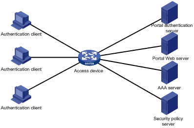
Authentication client
An authentication client is a Web browser that runs HTTP/HTTPS or a user host that runs a portal client. Security check for the user host is implemented through the interaction between the portal client and the security policy server. Only the H3C iNode client is supported.
Access device
An access device provides access services. It has the following functions:
· Redirects all HTTP or HTTPS requests of unauthenticated users to the portal Web server.
· Interacts with the portal authentication server and the AAA server to complete authentication, authorization, and accounting.
· Allows users that pass portal authentication to access authorized network resources.
Portal server
A portal server collectively refers to a portal authentication server and portal Web server.
The portal Web server pushes the Web authentication page to authentication clients and forwards user authentication information (username and password) to the portal authentication server. The portal authentication server receives authentication requests from authentication clients and interacts with the access device to authenticate users. The portal Web server is typically integrated with the portal authentication server and it can also be an independent server.
AAA server
The AAA server interacts with the access device to implement authentication, authorization, accounting for portal users. In a portal system, a RADIUS server can perform authentication, authorization, accounting for portal users, and an LDAP server can perform authentication for portal users.
Security policy server
The security policy server interacts with the portal client and the access device for security check and authorization for users. Only hosts that run portal clients can interact with the security policy server.
Portal authentication using a remote portal server
The components of a portal system interact as follows:
1. An unauthenticated user initiates authentication by accessing an Internet website through a Web browser. When receiving the HTTP or HTTPS request, the access device redirects it to the Web authentication page provided by the portal Web server. The user can also visit the authentication website to log in. The user must log in through the H3C iNode client for extended portal functions.
2. The user enters the authentication information on the authentication page/dialog box and submits the information. The portal Web server forwards the information to the portal authentication server. The portal authentication server processes the information and forwards it to the access device.
3. The access device interacts with the AAA server to implement authentication, authorization, accounting for the user.
4. If security policies are not imposed on the user, the access device allows the authenticated user to access networks.
If security policies are imposed on the user, the portal client, the access device, and the security policy server interact to check the user host. If the user passes the security check, the security policy server authorizes the user to access resources based on the check result.
Local portal service
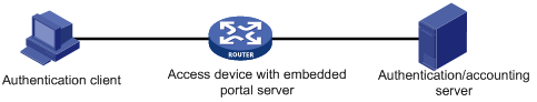
System components
As shown in Figure 2, a local portal system consists of an authentication client, access device, and AAA server. The access device acts as both the portal Web server and the portal authentication server to provide the local portal Web service for the authentication client. The authentication client can only be a Web browser, and it cannot be a user host that runs a portal client. Therefore, extended portal functions are not supported and no security policy server is required.
Portal page customization
To provide the local portal web service, you must customize a set of authentication pages that the device will push to users. You can customize multiple sets of authentication pages, compress each set of the pages to a .zip file, and upload the compressed files to the storage medium of the device. On the device, you must specify one of the files as the default authentication page file by using the default-logon-page command.
For more information about authentication page customization, see "Customizing authentication pages."
Portal authentication modes
Portal authentication has three modes: direct authentication, re-DHCP authentication, and cross-subnet authentication. In direct authentication and re-DHCP authentication, no Layer 3 forwarding devices exist between the authentication client and the access device. In cross-subnet authentication, Layer 3 forwarding devices can exist between the authentication client and the access device.
Direct authentication
A user manually configures a public IP address or obtains a public IP address through DHCP. Before authentication, the user can access only the portal Web server and predefined authentication-free websites. After passing authentication, the user can access other network resources. The process of direct authentication is simpler than that of re-DHCP authentication.
Re-DHCP authentication
Before a user passes authentication, DHCP allocates an IP address (a private IP address) to the user. The user can access only the portal Web server and predefined authentication-free websites. After the user passes authentication, DHCP reallocates an IP address (a public IP address) to the user. The user then can access other network resources. No public IP address is allocated to users who fail authentication. Re-DHCP authentication saves public IP addresses. For example, an ISP can allocate public IP addresses to broadband users only when they access networks beyond the residential community network.
Only the H3C iNode client supports re-DHCP authentication. IPv6 portal authentication does not support the re-DHCP authentication mode.
Cross-subnet authentication
Cross-subnet authentication is similar to direct authentication, except it allows Layer 3 forwarding devices to exist between the authentication client and the access device.
In direct authentication, re-DHCP authentication, and cross-subnet authentication, a user's IP address uniquely identifies the user. After a user passes authentication, the access device generates an ACL for the user based on the user's IP address to control forwarding of the packets from the user. Because no Layer 3 forwarding device exists between authentication clients and the access device in direct authentication and re-DHCP authentication, the access device can learn the user MAC addresses. The access device can enhance its capability of controlling packet forwarding by using the learned MAC addresses.
Portal authentication process
Direct authentication and cross-subnet authentication share the same authentication process. Re-DHCP authentication has a different process as it has two address allocation procedures.
Direct authentication/cross-subnet authentication process (with CHAP/PAP authentication)
Figure 3 Direct authentication/cross-subnet authentication process
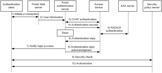
The direct/cross-subnet authentication process is as follows:
1. A portal user access the Internet through HTTP or HTTPS, and the HTTP or HTTPS packet arrives at the access device.
¡ If the packet matches a portal free rule, the access device allows the packet to pass.
¡ If the packet does not match any portal-free rule, the access device redirects the packet to the portal Web server. The portal Web server pushes the Web authentication page to the user for him to enter his username and password.
2. The portal Web server submits the user authentication information to the portal authentication server.
3. The portal authentication server and the access device exchange CHAP messages. This step is skipped for PAP authentication. The portal authentication server decides the method (CHAP or PAP) to use.
4. The portal authentication server adds the username and password into an authentication request packet and sends it to the access device. Meanwhile, the portal authentication server starts a timer to wait for an authentication reply packet.
5. The access device and the RADIUS server exchange RADIUS packets.
6. The access device sends an authentication reply packet to the portal authentication server to notify authentication success or failure.
7. The portal authentication server sends an authentication success or failure packet to the client.
8. If the authentication is successful, the portal authentication server sends an authentication reply acknowledgment packet to the access device.
If the client is an iNode client, the authentication process includes step 9 and step 10 for extended portal functions. Otherwise the authentication process is complete.
9. The client and the security policy server exchange security check information. The security policy server detects whether or not the user host installs anti-virus software, virus definition files, unauthorized software, and operating system patches.
10. The security policy server authorizes the user to access certain network resources based on the check result. The access device saves the authorization information and uses it to control access of the user.
Re-DHCP authentication process (with CHAP/PAP authentication)
Figure 4 Re-DHCP authentication process
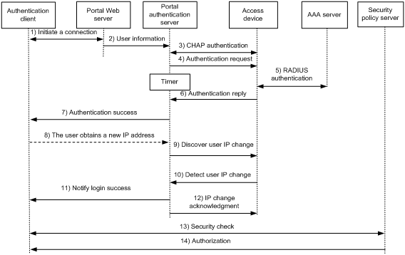
The re-DHCP authentication process is as follows:
Step 1 through step 7 are the same as those in the direct authentication/cross-subnet authentication process.
8. After receiving the authentication success packet, the client obtains a public IP address through DHCP. The client then notifies the portal authentication server that it has a public IP address.
9. The portal authentication server notifies the access device that the client has obtained a public IP address.
10. The access device detects the IP change of the client through DHCP and then notifies the portal authentication server that it has detected an IP change of the client IP.
11. After receiving the IP change notification packets sent by the client and the access device, the portal authentication server notifies the client of login success.
12. The portal authentication server sends an IP change acknowledgment packet to the access device.
Step 13 and step 14 are for extended portal functions.
13. The client and the security policy server exchanges security check information. The security policy server detects whether or not the user host installs anti-virus software, virus definition files, unauthorized software, and operating system patches.
14. The security policy server authorizes the user to access certain network resources based on the check result. The access device saves the authorization information and uses it to control access of the user.
Portal support for EAP
To use portal authentication that supports EAP, the portal authentication server and client must be the H3C IMC portal server and the H3C iNode portal client. Local portal authentication does not support EAP authentication.
Compared with username and password based authentication, digital certificate-based authentication ensures higher security.
The Extensible Authentication Protocol (EAP) supports several digital certificate-based authentication methods, for example, EAP-TLS. Working together with EAP, portal authentication can implement digital certificate-based user authentication.
Figure 5 Portal support for EAP working flow diagram
![]()
As shown in Figure 5, the authentication client and the portal authentication server exchange EAP authentication packets. The portal authentication server and the access device exchange portal authentication packets that carry the EAP-Message attributes. The access device and the RADIUS server exchange RADIUS packets that carry the EAP-Message attributes. The RADIUS server that supports the EAP server function processes the EAP packets encapsulated in the EAP-Message attributes, and provides the EAP authentication result.
The access device does not process but only transports EAP-Message attributes between the portal authentication server and the RADIUS server. Therefore, the access device requires no additional configuration to support EAP authentication.
Portal filtering rules
The access device uses portal filtering rules to control user traffic forwarding.
Based on the configuration and authentication status of portal users, the device generates the following categories of portal filtering rules:
· First category—The rule permits user packets that are destined for the portal Web server and packets that match the portal-free rules to pass through.
· Second category—For an authenticated user with no ACL authorized, the rule allows the user to access any destination network resources. For an authenticated user with an ACL authorized, the rule allows users to access resources permitted by the ACL. The device adds the rule when a user comes online and deletes the rule when the user goes offline.
The device supports the following types of authorization ACLs:
¡ Basic ACLs (ACL 2000 to ACL 2999).
¡ Advanced ACLs (ACL 3000 to ACL 3999).
¡ Layer 2 ACLs (ACL 4000 to ACL 4999).
For an authorization ACL to take effect, make sure the ACL exists and has ACL rules excluding rules configured with the counting, established, fragment, source-mac, or logging keyword. For more information about ACL rules, see ACL commands in ACL and QoS Command Reference.
· Third category—The rule redirects all HTTP or HTTPS requests from unauthenticated users to the portal Web server.
· Fourth category—For direct authentication and cross-subnet authentication, the rule forbids any user packets to pass through. For re-DHCP authentication, the device forbids user packets with private source addresses to pass.
After receiving a user packet, the device compares the packet against the filtering rules from the first category to the fourth category. Once the packet matches a rule, the matching process completes.
Portal support for portal proxy
In a portal network where a portal proxy is deployed, the portal proxy performs the following operations:
· Receives authentication requests from the portal authentication server and forwards the requests to the corresponding access devices.
· Receives authentication reply packets from the access devices and the forwards the reply packets to the portal authentication server.
In this way, the portal authentication server needs to manage only one NAS IP address, that is, the IP address of the portal proxy.
MAC-based quick portal authentication
MAC-based quick portal authentication is applicable to scenarios where users access the network frequently. It allows users to pass authentication without entering a username and password. MAC-based quick portal authentication is also called MAC-trigger authentication or transparent portal authentication.
A MAC binding server is required for MAC-trigger authentication. The MAC binding server records the MAC-to-account bindings of portal users for authentication. The account contains the portal authentication information of the user, including username and password.
Only IPv4 direct authentication supports MAC-based quick portal authentication.
The authentication is implemented as follows:
1. When a user accesses the network for the first time, the access device generates a MAC-trigger entry that records the user's MAC address and access interface. The user can access the network without performing portal authentication if the user's network traffic is below the free-traffic threshold.
2. When the user's network traffic reaches the threshold, the access device sends a MAC binding query to the MAC binding server.
3. The MAC binding server checks whether the MAC address of the user is bound with a portal user account.
¡ If a matching MAC-account binding exists, the MAC binding server sends the user authentication information to the access device to initiate portal authentication. The user is authenticated without entering the username and password.
- If the user fails portal authentication, an authentication failure message is returned to the user. The MAC-trigger entry of the user on the access device is deleted when the entry ages out.
- If the user passes portal authentication, the access device deletes the MAC-trigger entry of the user.
¡ If no matching MAC-account binding exists, the MAC binding server notifies the access device to perform normal portal authentication for the user.
- If the user fails portal authentication, an authentication failure message is returned to the user. The whole process is finished.
- If the user passes portal authentication, the access device sends the user's MAC address and authentication information to the MAC binding server for MAC-account binding. Additionally, the access device deletes the MAC-trigger entry of the user.
If a portal proxy is deployed, the portal proxy receives the MAC binding query request packets from access devices and forwards the packets to the MAC binding server. The portal proxy receives MAC binding query response packets and forwards the packets to the corresponding access devices.
The specific communication process is as follows:
1. The access device encapsulates the IP address and listening port number of the MAC binding server used by the interface into a cookie attribute. It adds the cookie attribute to the MAC binding query request and sends the request to the portal proxy.
2. The portal proxy resolves the request to get the IP address of the MAC binding server, and then forwards the request to the MAC binding server.
3. The MAC binding server checks whether the MAC address of the user is bound with a portal user account. According to the query result, it sends a query response packet to the portal proxy.
4. After receiving the query response packet, the portal proxy checks the user-to-access device entries. It identifies the IP address of the access device according to the IP address of the user, and then forwards the query response packet to the access device.
|
|
NOTE: For information about MAC binding server configuration, see the user manual of the server. |
Restrictions: Hardware compatibility with portal
Portal is supported only on CSPEX cards (excluding the CSPEX-1104-E card)CEPC cards.
Restrictions and guidelines: Portal configuration
Portal is supported only when the device operates in standard mode. For more information about the system operating modes, see device management in Fundamentals Configuration Guide.
Portal authentication through Web does not support security check for users. To implement security check, the client must be the H3C iNode client.
Portal authentication supports NAT traversal whether it is initiated by a Web client or an H3C iNode client. NAT traversal must be configured when the portal client is on a private network and the portal server is on a public network.
Portal authentication tasks at a glance
To configure portal authentication, perform the following tasks:
1. Configuring a remote or local portal service as needed
¡ Configuring a remote portal service
Configuring a remote portal authentication server
Configuring a portal Web server
¡ Configuring a local portal service
Configuring local portal service features
Configuring a portal Web server
2. Specifying the HTTPS redirect listening port number
This task is required only when you need to redirect users' HTTPS requests to the portal Web server.
3. Enabling portal authentication and specifying a portal Web server
¡ Enabling portal authentication on an interface
¡ Specifying a portal Web server on an interface
4. (Optional.) Configure parameters for preauthentication portal users
¡ Configuring a portal preauthentication policy
¡ Specifying a preauthentication IP address pool
5. (Optional.) Specifying a portal authentication domain
6. (Optional.) Controlling portal user access
¡ Configuring a portal-free rule
¡ Configuring an authentication source subnet
¡ Checking the issuing of category-2 portal filtering rules
¡ Setting the maximum number of portal users
¡ Enabling strict-checking on portal authorization information
¡ Allowing only users with DHCP-assigned IP addresses to pass portal authentication
¡ Specifying port numbers of Web proxy servers
¡ Blocking portal users that fail portal authentication
¡ Configuring portal HTTP and HTTPS attack defense
¡ Configuring the portal fail-permit feature
7. (Optional.) Configuring portal detection features
¡ Configuring online detection of portal users
¡ Configuring portal authentication server detection
¡ Configuring portal Web server detection
¡ Configuring portal user synchronization
8. (Optional.) Configuring attributes for portal packets and RADIUS packets
¡ Configuring portal packet attributes
You can configure the BAS-IP attributes for portal packets and specify the device ID.
¡ Excluding an attribute from portal protocol packets
¡ Configuring attributes for RADIUS packets
You can configure the NAS-Port-Id attribute format and apply a NAS-ID profile to an interface.
9. (Optional.) Configuring MAC-based quick portal authentication
a. Configuring a MAC binding server
b. Specifying a MAC binding server on an interface
c. Specifying the portal proxy for MAC binding servers
This task is required only when a portal proxy exists in the network.
10. (Optional.) Configuring online and offline related features for portal users
¡ Logging out online portal users
¡ Enabling portal user login/logout logging
11. Configuring extended portal authentication features
¡ (Optional.) Setting the user traffic backup threshold
¡ (Optional.) Configuring Web redirect
¡ Refreshing Rule ARP or Rule ND entries
¡ Obtaining user access information from ARP or ND entries
On an IPoE Web authentication network, this task is required when DHCP access users and the portal authentication server belong to different VPNs.
Prerequisites for portal authentication
The portal feature provides a solution for user identity authentication and security check. To complete user identity authentication, portal must cooperate with RADIUS.
Before you configure portal, you must complete the following tasks:
· The portal authentication server, portal Web server, and RADIUS server have been installed and configured correctly.
· To use the re-DHCP portal authentication mode, make sure the DHCP relay agent is enabled on the access device, and the DHCP server is installed and configured correctly.
· The portal client, access device, and servers can reach each other.
· To use the remote RADIUS server, configure usernames and passwords on the RADIUS server, and configure the RADIUS client on the access device. For information about RADIUS client configuration, see "Configuring AAA."
· To implement extended portal functions, install and configure CAMS EAD or IMC EAD. Make sure the ACLs configured on the access device correspond to the isolation ACL and the security ACL on the security policy server. For installation and configuration about the security policy server, see CAMS EAD Security Policy Component User Manual or IMC EAD Security Policy Help.
Configuring a remote portal authentication server
About configuring the remote portal authentication server
With portal authentication enabled, the device searches for a portal authentication server for a received portal request packet according to the source IP address and VPN information of the packet.
· If a matching portal authentication server is found, the device regards the packet valid and sends an authentication response packet to the portal authentication server. After a user logs in to the device, the user interacts with the portal authentication server as needed.
· If no matching portal authentication server is found, the device drops the packet.
Restrictions and guidelines
Do not delete a portal authentication server in use. Otherwise, users authenticated by that server cannot log out correctly.
Procedure
1. Enter system view.
system-view
2. Create a portal authentication server and enter its view.
portal server server-name
You can create multiple portal authentication servers.
3. Specify the IP address of the portal authentication server.
ip ipv4-address [ vpn-instance vpn-instance-name] [ key { cipher | simple } string ]
IPv6:
ipv6 ipv6-address [ vpn-instance vpn-instance-name ] [ key { cipher | simple } string ]
By default, no portal authentication server is specified.
4. (Optional.) Set the destination UDP port number used by the device to send unsolicited portal packets to the portal authentication server.
port port-number
By default, the UDP port number is 50100.
This port number must be the same as the listening port number specified on the portal authentication server.
In a portal proxy network, make sure this port number is the same as the listening port number specified on the portal proxy.
5. (Optional.) Specify the portal authentication server type.
server-type { cmcc | imc }
By default, the portal authentication server type is IMC.
The specified server type must be the same as the type of the portal authentication server actually used.
6. (Optional.) Set the maximum number of times and the interval for retransmitting a logout notification packet.
logout-notify retry retries interval interval
By default, the device does not retransmit a logout notification packet.
7. (Optional.) Configure the device to periodically register with the portal authentication server.
server-register [ interval interval-value ]
By default, the device does not register with a portal authentication server.
Configuring a portal Web server
To configure a portal Web server, perform the following tasks:
1. Configure basic parameters for a portal Web server
2. (Optional.) Enabling the captive-bypass feature
3. (Optional.) Configuring a match rule for URL redirection
Configure basic parameters for a portal Web server
1. Enter system view.
system-view
2. Create a portal Web server and enter its view.
portal web-server server-name
You can create multiple portal Web servers.
3. Specify the VPN instance to which the portal Web server belongs.
vpn-instance vpn-instance-name
By default, the portal Web server belongs to the public network.
4. Specify the URL of the portal Web server.
url url-string
By default, no URL is specified for a portal Web server.
5. Configure the parameters to be carried in the URL when the device redirects it to users.
url-parameter param-name { nas-id | nas-port-id | original-url | source-address | source-mac [ encryption { aes | des } key { cipher | simple } string ] | value expression }
By default, no redirection URL parameters are configured.
6. (Optional.) Specify the portal Web server type.
server-type { cmcc | imc }
By default, the portal Web server type is IMC.
This configuration is applicable to only to the remote portal service.
The specified server type must be the same as the type of the portal Web server actually used.
Enabling the captive-bypass feature
About the captive-bypass feature
Typically, when iOS mobile devices or some Android mobile devices are connected a portal-enabled network, the device pushes the authentication page to the mobile devices.
The captive-bypass feature enables the device to push the portal authentication page to the iOS and Android devices only when the users access the Internet by using a browser. If the users do not perform authentication but press the home button to return to the desktop, the Wi-Fi connection is terminated. To maintain the Wi-Fi connection in such cases, you can enable the optimized captive-bypass feature.
When optimized captive-bypass is enabled, the portal authentication page is automatically pushed to iOS mobile devices after they connects to the network. Users can perform authentication on the page or press the home button to return to the desktop without performing authentication, and the Wi-Fi connection is not terminated.
Procedure
1. Enter system view.
system-view
2. Enter portal Web server view.
portal web-server server-name
3. Enable the captive-pass feature.
captive-bypass [ optimize ] enable
By default, the captive-bypass feature is disabled.
Configuring a match rule for URL redirection
About match rules for URL redirection
A URL redirection match rule matches HTTP or HTTPS requests by user-requested URL or User-Agent information, and redirects the matching HTTP or HTTPS requests to the specified redirection URL.
For a portal Web server, you can configure the url command and the if-match command for URL redirection. The url command redirects all HTTP or HTTPS requests from unauthenticated users to the portal Web server for authentication. The if-match command allows for flexible URL redirection by redirecting specific HTTP or HTTPS requests to specific redirection URLs.
Restrictions and guidelines
For a user to successfully access a redirection URL, configure a portal-free rule to allow HTTP or HTTPS requests destined for the redirection URL to pass. For information about configuring portal-free rules, see the portal free-rule command.
If both the url and if-match commands are executed, the if-match command takes priority to perform URL redirection.
Procedure
1. Enter system view.
system-view
2. Enter portal Web server view.
portal web-server server-name
3. Configure a match rule for URL redirection.
if-match { original-url url-string redirect-url url-string [ url-param-encryption { aes | des } key { cipher | simple } string ] | user-agent string redirect-url url-string }
Specifying the HTTPS redirect listening port number
Restrictions and guidelines
To avoid service unavailability caused by port conflict, do not specify a TCP port number used by a well-known protocol or used by any other TCP-based service. To display TCP port numbers that have been used by services, use the display tcp command. For more information about this command, see IP performance optimization commands in Layer 3—IP Services Command Reference.
If you perform this task multiple times, the most recent configuration takes effect.
Procedure
1. Enter system view.
system-view
2. Specify the HTTPS redirect listening port number.
http-redirect https-port port-number
By default, no HTTPS redirect listening port number is specified.
For more information about how to specify the HTTPS redirect listening port number, see HTTP redirect in Layer 3—IP Services Configuration Guide.
Configuring local portal service features
About the local portal service
After a local portal service is configured, the device acts as the portal Web server and portal authentication server to perform portal authentication on users. The portal authentication page file is saved in the root directory of the device.
Restrictions and guidelines for configuring local portal service features
For an interface to use the local portal service, the URL of the portal Web server specified for the interface must meet the following requirements:
· The IP address in the URL must be the IP address of a Layer 3 interface (except 127.0.0.1) on the device, and the IP address must be reachable to portal clients.
· The URL must be ended with /portal/. For example: http://1.1.1.1/portal/.
You must customize the authentication pages and upload them to the device.
Customizing authentication pages
About customizing authentication pages
Authentication pages are HTML files. Local portal authentication requires the following authentication pages:
· Logon page
· Logon success page
· Logon failure page
· Online page
· System busy page
· Logoff success page
You must customize the authentication pages, including the page elements that the authentication pages will use, for example, back.jpg for authentication page Logon.htm.
Follow the authentication page customization rules when you edit the authentication page files.
File name rules
The names of the main authentication page files are fixed (see Table 1). You can define the names of the files other than the main authentication page files. File names and directory names are case insensitive.
Table 1 Main authentication page file names
|
Main authentication page |
File name |
|
Logon page |
logon.htm |
|
Logon success page |
logonSuccess.htm |
|
Logon failure page |
logonFail.htm |
|
Online page Pushed after the user gets online for online notification |
online.htm |
|
System busy page Pushed when the system is busy or the user is in the logon process |
busy.htm |
|
Logoff success page |
logoffSuccess.htm |
Page request rules
The local portal Web service supports only Get and Post requests.
· Get requests—Used to get the static files in the authentication pages and allow no recursion. For example, if file Logon.htm includes contents that perform Get action on file ca.htm, file ca.htm cannot include any reference to file Logon.htm.
· Post requests—Used when users submit username and password pairs, log in, and log out.
Post request attribute rules
1. Observe the following requirements when editing a form of an authentication page:
¡ An authentication page can have multiple forms, but there must be one and only one form whose action is logon.cgi. Otherwise, user information cannot be sent to the access device.
¡ The username attribute is fixed as PtUser. The password attribute is fixed as PtPwd.
¡ The value of the PtButton attribute is either Logon or Logoff, which indicates the action that the user requests.
¡ A logon Post request must contain PtUser, PtPwd, and PtButton attributes.
¡ A logoff Post request must contain the PtButton attribute.
2. Authentication pages logon.htm and logonFail.htm must contain the logon Post request.
The following example shows part of the script in page logon.htm.
<form action=logon.cgi method = post >
<p>User name:<input type="text" name = "PtUser" style="width:160px;height:22px" maxlength=64>
<p>Password :<input type="password" name = "PtPwd" style="width:160px;height:22px" maxlength=32>
<p><input type=SUBMIT value="Logon" name = "PtButton" style="width:60px;" onclick="form.action=form.action+location.search;">
</form>
3. Authentication pages logonSuccess.htm and online.htm must contain the logoff Post request.
The following example shows part of the script in page online.htm.
<form action=logon.cgi method = post >
<p><input type=SUBMIT value="Logoff" name="PtButton" style="width:60px;">
</form>
Page file compression and saving rules
You must compress the authentication pages and their page elements into a standard zip file.
· The name of a zip file can contain only letters, numbers, and underscores.
· The authentication pages must be placed in the root directory of the zip file.
· Zip files can be transferred to the device through FTP or TFTP and must be saved in the root directory of the device.
Examples of zip files on the device:
<Sysname> dir
Directory of flash:
1 -rw- 1405 Feb 28 2008 15:53:20 aaa.zip
0 -rw- 1405 Feb 28 2008 15:53:31 bbb.zip
2 -rw- 1405 Feb 28 2008 15:53:39 ccc.zip
3 -rw- 1405 Feb 28 2008 15:53:44 ddd.zip
2540 KB total (1319 KB free)
Redirecting authenticated users to a specific webpage
To make the device automatically redirect authenticated users to a specific webpage, do the following in logon.htm and logonSuccess.htm:
1. In logon.htm, set the target attribute of Form to _blank.
See the contents in gray:
<form method=post action=logon.cgi target="_blank">
2. Add the function for page loading pt_init() to logonSuccess.htm.
See the contents in gray:
<html>
<head>
<title>LogonSuccess</title>
<script type="text/javascript" language="javascript" src="pt_private.js"></script>
</head>
<body onload="pt_init();" onbeforeunload="return pt_unload();">
... ...
</body>
</html>
Configuring a local portal Web service
Prerequisites
Before you configure an HTTPS-based local portal Web service, you must complete the following tasks:
· Configure a PKI policy, obtain the CA certificate, and request a local certificate. For more information, see "Configuring PKI."
· Configure an SSL server policy, and specify the PKI domain configured in the PKI policy.
During SSL connection establishment, the user browser might display a message that it cannot verify server identity by certificate. For users to perform portal authentication without checking such a message, configure an SSL server policy to request a client-trusted certificate on the device. The name of the policy must be https_redirect. For more information about SSL server policy configuration, see "Configuring SSL."
Procedure
1. Enter system view.
system-view
2. Create an HTTP- or HTTPS-based local portal Web service and enter its view.
portal local-web-server { http | https ssl-server-policy policy-name [ tcp-port port-number ] }
3. Specify the default authentication page file for the local portal Web service.
default-logon-page filename
By default, no default authentication page file is specified for the local portal Web service.
To provide local portal Web service for users, you must use this command to specify a customized authentication page file as the default authentication page file.
4. (Optional.) Configure the listening TCP port for the local portal Web service.
tcp-port port-number
By default, the HTTP service listening port number is 80 and the HTTPS service listening port number is the TCP port number set by the portal local-web-server command.
5. (Optional.) Bind an endpoint type to an authentication page file.
logon-page bind device-type type-name file file-name
By default, no endpoint type is bound to an authentication page file.
Enabling portal authentication on an interface
General restrictions and guidelines for enabling portal authentication
When you enable portal authentication on an interface, follow these restrictions and guidelines:
· If the device is connected to the RADIUS and portal servers through interfaces on CSPC cards (exluding CSPC-GE16XP4L-E, CSPC-GE24L-E, and CSPC-GP24GE8XP2L-E cards) or CMPE-1104 cards, set the UDP port numbers as follows:
¡ Set the RADIUS authentication and accounting port numbers to 1812 and 1813, respectively.
¡ Set the portal listening port number to 2000.
For more information about specifying the port numbers for RADIUS authentication and RADIUS accounting on the device, see "Configuring AAA."
· As a best practice, do not apply a QoS policy to an interface enabled with portal authentication by using the qos apply policy command. If you need to apply a QoS policy on the interface, do it under the guidance of the technical support.
For more information about the qos apply policy command, see ACL and QoS Command Reference.
· For portal authentication to take effect on an Ethernet interface, do not add the Ethernet interface to an aggregation group.
· You can enable both IPv4 portal authentication and IPv6 portal authentication on an interface.
Restrictions and guidelines for enabling cross-subnet portal authentication
When you configure cross-subnet portal authentication (layer3) on an interface, follow these restrictions and guidelines:
· On an interface enabled with cross-subnet IPv6 portal authentication, IPv6 portal users on the interface cannot receive IPv6 multicast data after they join IPv6 multicast groups.
For more information about users joining IPv6 multicast groups, see MLD configuration in IP Multicast Configuration Guide.
· Cross-subnet authentication mode (layer3) does not require Layer 3 forwarding devices between the access device and the portal authentication clients. However, if a Layer 3 forwarding device exists between the authentication client and the access device, you must use the cross-subnet portal authentication mode.
Restrictions and guidelines for enabling re-DHCP portal authentication
When you configure re-DHCP portal authentication on an interface, follow these restrictions and guidelines:
· Make sure the interface has a valid IP address before you enable re-DHCP portal authentication on the interface. For re-DHCP portal authentication to take effect after the IP address of the interface changes, you must disable portal authentication and then enable re-DHCP portal authentication.
· With re-DHCP portal authentication, configure authorized ARP on the interface as a best practice to make sure only valid users can access the network. With authorized ARP configured on the interface, the interface learns ARP entries only from the users who have obtained a public address from DHCP.
· For successful re-DHCP portal authentication, make sure the BAS-IP/BAS-IPv6 attribute value is the same as the device IP or IPv6 address specified on the portal authentication server. To configure the BAS-IP/BAS-IPv6 attribute, use the portal { bas-ip | bas-ipv6 } command.
· An IPv6 portal server does not support re-DHCP portal authentication.
Procedure
1. Enter system view.
system-view
2. Enter Layer 3 interface view.
interface interface-type interface-number
3. Enable portal authentication.
IPv4:
portal enable method { direct | layer3 | redhcp }
IPv6:
portal ipv6 enable method { direct | layer3 }
By default, portal authentication is disabled.
Specifying a portal Web server on an interface
About specifying a portal Web server on an interface
With a portal Web server specified on an interface, the device redirects the HTTP requests of portal users on the interface to the portal Web server.
You can specify both an IPv4 portal Web server and an IPv6 portal Web server on an interface.
Procedure
1. Enter system view.
system-view
2. Enter Layer 3 interface view.
interface interface-type interface-number
3. Specify a portal Web server on the interface.
portal [ ipv6 ] apply web-server server-name [ fail-permit ]
By default, no portal Web servers are specified on an interface.
Configuring a portal preauthentication policy
About portal preauthentication policies
A portal preauthentication policy defines user attributes assigned to preauthentication portal users on a portal-enabled interface after the users obtain IP addresses. Before the preauthentication users pass portal authentication, they have limited access to the network based on the assigned user attributes (such as ACL, user profile, and CAR). After the users pass portal authentication, they are assigned new attributes by the AAA server. After the users go offline, they are re-assigned user attributes in the preauthentication policy.
Restrictions and guidelines
The portal preauthentication policy takes effect only on portal users with IP addresses obtained through DHCP or DHCPv6.
The portal preauthentication policy does not take effect on interfaces enabled with cross-subnet portal authentication.
If you modify a user attribute (or its contents) in the portal preauthentication policy, the modification immediately takes effect on the policy-applied interface for unauthenticated portal users.
For the ACL specified in the portal preauthentication policy, the following rules apply:
· If the traffic of preauthentication users matches a rule in the ACL, the device processes the traffic based on the permit or deny statement of the rule.
· If the ACL does not exist or the permitted destination IP address of a rule in the ACL is specified as any, preauthentication users can directly access network resources.
· If the ACL does not have rules, preauthentication users can access network resources after passing portal authentication.
· If the traffic of preauthentication users does not match any rule in the ACL, the device pushes the authentication page to the users. The users can access the network resources after passing authentication.
· To avoid user login failure, do not specify a source IPv4 or IPv6 address when you configure a rule in the ACL.
Procedure
1. Enter system view.
system-view
2. Create a portal preauthentication policy and enter its view.
portal pre-auth policy policy-name
3. Configure a user attribute in the portal preauthentication policy.
user-attribute { acl acl-number | car { inbound | outbound } cir committed-information-rate [ pir peak-information-rate ] | user-profile profile-name }
4. Return to system view.
quit
5. Enter Layer 3 Ethernet interface view.
interface interface-type interface-number
6. Apply a portal preauthentication policy to the interface.
portal [ ipv6 ] apply pre-auth-policy policy-name
By default, no portal preauthentication policy is applied to an interface.
Specifying a preauthentication IP address pool
About preauthentication IP address pools
You must specify a preauthentication IP address pool on a portal-enabled interface in the following situation:
· Portal users access the network through a subinterface of the portal-enabled interface.
· The subinterface does not have an IP address.
· Portal users need to obtain IP addresses through DHCP.
After a user connects to a portal-enabled interface, the user uses an IP address for portal authentication according to the following rules:
· If the interface is configured with a preauthentication IP address pool, the user uses the following IP address:
¡ If the client is configured to obtain an IP address automatically through DHCP, the user obtains an address from the specified IP address pool.
¡ If the client is configured with a static IP address, the user uses the static IP address. However, if the interface does not have an IP address, users using static IP addresses cannot pass authentication.
· If the interface has an IP address but no preauthentication IP pool specified, the user uses the static IP address or the IP address obtained from a DHCP server.
· If the interface has no IP address or preauthentication IP pool specified, the user cannot perform portal authentication.
Restrictions and guidelines
This configuration takes effect only when the direct IPv4 portal authentication is enabled on the interface.
Make sure the specified IP address pool exists and is complete. Otherwise, the user cannot obtain the IP address and cannot perform portal authentication.
If the portal user does not perform authentication or fails to pass authentication, the assigned IP address is still retained.
The preauthentication IP address pool specified for an interface no longer takes effect after the configuration of the VPN instance associated with the interface changes. For the preauthentication IP address pool to take effect, disable and then re-enable portal authentication, or alternatively, remove the pool and then respecify it on the interface. The VPN instance configuration changes include the following:
· Associate a VPN instance with the interface by using the ip binding vpn-instance command.
· Remove the association of the interface with a VPN instance by using the undo ip binding vpn-instance command.
· Delete the VPN instance associated with the interface by using the undo ip vpn-instance command in system view.
· Change the configuration of the VPN instance associated with the interface.
Procedure
1. Enter system view.
system-view
2. Enter Layer 3 interface view.
interface interface-type interface-number
3. Specify a preauthentication IP address pool on the interface.
portal [ ipv6 ] pre-auth ip-pool pool-name
By default, no preauthentication IP address pool is specified on an interface.
Specifying a portal authentication domain
About portal authentication domains
An authentication domain defines a set of authentication, authorization, and accounting policies. Each portal user belongs to an authentication domain and is authenticated, authorized, and accounted in the domain.
With an authentication domain specified on an interface, the device uses the authentication domain for AAA of portal users. This allows for flexible portal access control.
Restrictions and guidelines for specifying a portal authentication domain
The device selects the authentication domain for a portal user in this order:
1. ISP domain specified for the interface.
2. ISP domain carried in the username.
3. System default ISP domain.
If the chosen domain does not exist on the device, the device searches for the ISP domain configured to accommodate users assigned to nonexistent domains. If no such ISP domain is configured, user authentication fails. For information about ISP domains, see "Configuring AAA."
For the ACL specified in the portal authentication domain, the following rules apply:
· If the traffic of authenticated users matches a rule in the ACL, the device processes the traffic based on the permit or deny statement of the rule.
· If the traffic of authenticated users does not match any rule in the ACL, the device permits the traffic.
· To avoid user login failure, do not specify a source IPv4 or IPv6 address when you configure a rule in the ACL.
· If a card generates a minor memory alarm notification, the card cannot issue authorization ACLs to subsequent authenticated portal users until the memory alarm is removed. Ten minutes after the authorization ACL issuing failure for an authenticated portal user, the authenticated portal user is logged out. For more information about the minor memory alarm notification, see device management in Fundamentals Configuration Guide.
Procedure
1. Enter system view.
system-view
2. Enter Layer 3 interface view.
interface interface-type interface-number
3. Specify an portal authentication domain on the interface.
portal [ ipv6 ] domain domain-name
By default, no portal authentication domain is specified on an interface.
You can specify both an IPv4 portal authentication domain and an IPv6 portal authentication domain on an interface.
Controlling portal user access
Configuring a portal-free rule
About portal-free rules
A portal-free rule allows specified users to access specified external websites without portal authentication.
The matching items for a portal-free rule include the host name, source/destination IP address, TCP/UDP port number, VLAN, and access interface. Packets matching a portal-free rule will not trigger portal authentication, so users sending the packets can directly access the specified external websites.
Restrictions and guidelines for configuring a portal-free rule
You cannot configure two or more portal-free rules with the same filtering criteria. Otherwise, the system prompts that the rule already exists.
Regardless of whether portal authentication is enabled or not, you can only add or remove a portal-free rule. You cannot modify it.
Configuring an IP-based portal-free rule
1. Enter system view.
system-view
2. Configure an IP-based portal-free rule.
IPv4:
portal free-rule rule-number { destination ip { ipv4-address { mask-length | mask } | any } [ tcp tcp-port-number | udp udp-port-number ] | source ip { ipv4-address { mask-length | mask } | any } [ tcp tcp-port-number | udp udp-port-number ] } * [ interface interface-type interface-number ]
IPv6:
portal free-rule rule-number { destination ipv6 { ipv6-address prefix-length | any } [ tcp tcp-port-number | udp udp-port-number ] | source ipv6 { ipv6-address prefix-length | any } [ tcp tcp-port-number | udp udp-port-number ] } * [ interface interface-type interface-number ]
Configuring a source-based portal-free rule
1. Enter system view.
system-view
2. Configure a source-based portal-free rule.
portal free-rule rule-number source { interface interface-type interface-number | vlan vlan-id } *
The vlan vlan-id option takes effect only on portal users that access the network through VLAN interfaces. If you specify both a VLAN and an interface, the interface must belong to the VLAN.
Configuring a destination-based portal-free rule
1. Enter system view.
system-view
2. Configure a destination-based portal-free rule.
portal free-rule rule-number destination host-name
By default, no destination-based portal-free rules are configured.
Before you configure destination-based portal-free rules, make sure a DNS server has been deployed on the network.
Configuring an authentication source subnet
About authentication source subnets
By configuring authentication source subnets, you specify that only HTTP or HTTPS packets from users on the authentication source subnets can trigger portal authentication. If an unauthenticated user is not on any authentication source subnet, the access device discards all the user's HTTP or HTTPS packets that do not match any portal-free rule.
Restrictions and guidelines
Authentication source subnets apply only to cross-subnet portal authentication.
In direct or re-DHCP portal authentication mode, a portal user and its access interface (portal-enabled) are on the same subnet. It is not necessary to specify the subnet as the authentication source subnet.
· In direct mode, the access device regards the authentication source subnet as any source IP address.
· In re-DHCP mode, the access device regards the authentication source subnet on an interface as the subnet to which the private IP address of the interface belongs.
You can configure multiple authentication source subnets. If the source subnets overlap, the subnet with the largest address scope (with the smallest mask or prefix) takes effect.
Procedure
1. Enter system view.
system-view
2. Enter Layer 3 interface view.
interface interface-type interface-number
3. Configure a portal authentication source subnet.
IPv4:
portal layer3 source ipv4-network-address { mask-length | mask }
IPv6:
portal ipv6 layer3 source ipv6-network-address prefix-length
By default, users from any subnets must pass portal authentication.
Checking the issuing of category-2 portal filtering rules
About checking the issuing of category-2 portal filtering rules
Category-2 portal filtering rules permit authenticated users to access authorized network resources. By default, the device allows an authenticated user to come online as long as a card has issued a category-2 portal filtering rule for the user. Users coming online from global interfaces might fail to access network resources because some member ports might not have category-2 rules for the users. To resolve this issue, enable the device to check the issuing of category-2 portal filtering rules. Then, the device allows users to come online only when all cards have issued category-2 portal filtering rules for the users.
As a best practice, perform this task when portal authentication is enabled on a global interface.
Procedure
1. Enter system view.
system-view
2. Enable the device to check the issuing of category-2 portal filtering rules.
portal user-rule assign-check enable
By default, the device does not check the issuing of category-2 portal filtering rules.
Setting the maximum number of portal users
About setting the maximum number of portal users
Perform this task to control the total number of portal users in the system, and the maximum number of IPv4 or IPv6 portal users on an interface.
Restrictions and guidelines for setting the maximum number of portal users
Make sure the maximum combined number of IPv4 and IPv6 portal users specified on all interfaces does not exceed the system-allowed maximum number. Otherwise, the exceeding number of portal users will not be able to log in to the device.
Setting the global maximum number of portal users
1. Enter system view.
system-view
2. Set the global maximum number of portal users.
portal max-user max-number
By default, no limit is set on the global number of portal users.
If you set the global maximum number smaller than the number of current online portal users on the device, this configuration still takes effect. The online users are not affected but the system forbids new portal users to log in.
Setting the maximum number of portal users on an interface
1. Enter system view.
system-view
2. Enter Layer 3 interface view.
interface interface-type interface-number
3. Set the maximum number of portal users.
portal { ipv4-max-user | ipv6-max-user } max-number
By default, no limit is set on the number of portal users on an interface.
If you set the maximum number smaller than the current number of portal users on an interface, this configuration still takes effect. The online users are not affected but the system forbids new portal users to log in from the interface.
Enabling strict-checking on portal authorization information
About strict-checking on portal authorization information
The strict checking mode allows a portal user to stay online only when the authorized information for the user is successfully deployed on the interface.
You can enable strict checking on authorized ACLs, authorized user profiles, or both. If you enable both ACL checking and user profile checking, the user will be logged out if either checking fails.
An ACL/user profile checking fails when the authorized ACL/user profile does not exist on the device or the ACL/user profile fails to be deployed.
Restrictions and guidelines
The user profile feature is disabled temporarily after an active/standby MPU switchover and is resumed after cards have synchronized user information with the active MPU. To determine whether an active/standby MPU switchover has completed, use the display device command or observe the LEDs on the cards. For more information about the display device command, see device management commands in Fundamentals Command Reference.
Procedure
1. Enter system view.
system-view
2. Enter Layer 3 interface view.
interface interface-type interface-number
3. Enable strict checking on portal authorization information.
portal authorization { acl | user-profile } strict-checking
By default, strict checking on portal authentication information is disabled on an interface. Portal users stay online even when the authorized ACLs or user profiles do not exist or fail to be deployed.
Allowing only users with DHCP-assigned IP addresses to pass portal authentication
About allowing only users with DHCP-assigned IP addresses to pass portal authentication
This feature allows only users with DHCP-assigned IP addresses to pass portal authentication. Users with static IP addresses cannot pass portal authentication to come online. Use this feature to ensure that only users with valid IP addresses can access the network.
Restrictions and guidelines
This feature takes effect only on a network where the access device also acts as the DHCP server.
To ensure that IPv6 users can pass portal authentication when only users with DHCP-assigned IP addresses to pass portal authentication, disable the temporary IPv6 address feature on terminal devices. Otherwise, IPv6 users will use temporary IPv6 addresses to access the IPv6 network and will fail portal authentication.
This configuration does not affect the online portal users.
Procedure
1. Enter system view.
system-view
2. Enter Layer 3 interface view.
interface interface-type interface-number
3. Allow only users with DHCP-assigned IP addresses to pass portal authentication.
portal [ ipv6 ] user-dhcp-only
By default, both users with IP addresses obtained through DHCP and users with static IP addresses can pass authentication to come online.
Specifying port numbers of Web proxy servers
About portal authentication support for Web proxy servers
To allow HTTP or HTTPS requests proxied by Web proxy servers to trigger portal authentication, specify the port numbers of the Web proxy servers on the device. If a Web proxy server port is not specified on the device, HTTP or HTTPS requests proxied by the Web proxy server are dropped, and portal authentication cannot be triggered.
Restrictions and guidelines
Make sure HTTP and HTTPS attack defense is disabled when you perform this task.
Do not specify TCP port number 80 or 443 as the port numbers for Web proxy servers because 80 and 443 are port numbers reserved for portal.
You can specify a maximum of 64 Web proxy server ports for HTTP and HTTPS.
Do not specify the same Web proxy server port for HTTP and HTTPS.
If a user's browser uses the Web Proxy Auto-Discovery (WPAD) protocol to discover Web proxy servers, you must perform the following tasks on the device:
· Specify the port numbers of the Web proxy servers on the device.
· Configure portal-free rules to allow user packets destined for the IP address of the WPAD server to pass without authentication.
If portal users enable Web proxy in their browsers, the users must add the IP address of the portal authentication server as a proxy exception in their browsers. Then, HTTP or HTTPS packets that the users send to the portal authentication server will not be sent to Web proxy servers.
Procedure
1. Enter system view.
system-view
2. Specify the port number of a Web proxy server.
portal web-proxy { http | https } port port-number
By default, no port numbers of Web proxy servers are specified. Proxied HTTP and HTTPS requests are dropped.
Blocking portal users that fail portal authentication
About blocking portal users that fail portal authentication
This feature prevents exhaustive password cracking. It blocks a portal user if the user consecutively fails authentication for the specified times within the failure detection period. All authentication requests from the user are dropped by the device till the blocking times out. The blocked portal user can perform portal authentication again when the blocking timeout time expires.
Restrictions and guidelines
This feature does not block preauthentication portal users.
Procedure
1. Enter system view.
system-view
2. Configure the device to block portal users that fail portal authentication for the specified times within the specified period.
portal user-block failed-times failed-times period period
By default, the device does not block portal users that fail portal authentication.
3. Set the portal user blocking timeout time.
portal user-block reactive period
By default, the portal user blocking timeout time is 30 minutes.
If you set the portal user blocking timeout time to 0 minutes, blocked portal users cannot perform portal authentication.
Configuring portal HTTP and HTTPS attack defense
About portal HTTP and HTTPS attack defense
Use this feature to avoid high resource usage caused by excessive HTTP and HTTPS requests from unauthenticated portal users.
This feature counts the number of HTTP and HTTPS requests to be redirected on a per destination IP address basis. If the number of HTTP and HTTPS requests for a destination IP address reaches the blocking threshold within a statistical interval, the device starts a blocking timer for the IP address. Before the blocking timer expires, the device discards all HTTP requests destined for the IP address.
You can set the maximum number of destination IP addresses that can be monitored by the device for portal HTTP and HTTPS attack defense.
Procedure
1. Enter system view.
system-view
2. Enable portal HTTP and HTTPS attack defense.
portal http-defense enable
By default, portal HTTP and HTTPS attack defense is disabled.
3. Set the portal HTTP and HTTPS attack defense parameters.
portal http-defense { block-timeout minutes | statistics-interval value | threshold number } *
By default, the blocking timer is 10 minutes, the statistical interval for counting redirected HTTP and HTTPS packets is 5 minutes, and the blocking threshold is 6000 packets.
4. Set the maximum number of monitored destination IP addresses in portal HTTP and HTTPS attack defense.
portal http-defense max-ip-number max-ip-number
By default, the device can monitor a maximum of 4096 destination IP addresses to perform portal HTTP and HTTPS attack defense.
Enabling portal roaming
About portal roaming
If portal roaming is enabled on a VLAN interface, an online portal user can access resources from any Layer 2 port in the VLAN without re-authentication.
If portal roaming is disabled, to access external network resources from a Layer 2 port different from the current access port in the VLAN, the user must do the following:
1. Logs out from the current port.
2. Re-authenticates on the new Layer 2 port.
Restrictions and guidelines
Portal roaming takes effect only on portal users logging in from VLAN interfaces. It does not take effect on portal users logging in from common Layer 3 interface.
You cannot enable portal roaming when online portal users or preauthentication portal users exist on the device.
Procedure
1. Enter system view.
system-view
2. Enable portal roaming.
portal roaming enable
By default, portal roaming is disabled.
Configuring the portal fail-permit feature
About the portal fail-permit feature
Perform this task to configure the portal fail-permit feature on an interface. When the access device detects that the portal authentication server or portal Web server is unreachable, it allows users on the interface to have network access without portal authentication.
If you enable fail-permit for both a portal authentication server and a portal Web server on an interface, the interface does the following:
· Disables portal authentication when either server is unreachable.
· Resumes portal authentication when both servers are reachable.
After portal authentication resumes, unauthenticated users must pass portal authentication to access the network. Users who have passed portal authentication before the fail-permit event can continue accessing the network.
Procedure
1. Enter system view.
system-view
2. Enter Layer 3 interface view.
interface interface-type interface-number
3. Enable portal fail-permit for a portal authentication server.
portal [ ipv6 ] fail-permit server server-name
By default, portal fail-permit is disabled for a portal authentication server.
4. Enable portal fail-permit for a portal Web server.
portal [ ipv6 ] apply web-server server-name [ fail-permit ]
By default, portal fail-permit is disabled for a portal Web server.
Configuring portal detection features
Configuring online detection of portal users
About online detection for portal users
Configure online detection to quickly detect abnormal logouts of portal users.
· Configure ARP or ICMP detection for IPv4 portal users.
· Configure ND or ICMPv6 detection for IPv6 portal users.
If the device receives no packets from a portal user within the idle time, the device detects the user's online status as follows:
· ICMP or ICMPv6 detection—Sends ICMP or ICMPv6 requests to the user at configurable intervals to detect the user status.
¡ If the device receives a reply within the maximum number of detection attempts, it considers that the user is online and stops sending detection packets. Then the device resets the idle timer and repeats the detection process when the timer expires.
¡ If the device receives no reply after the maximum number of detection attempts, the device logs out the user.
· ARP or ND detection—Sends ARP or ND requests to the user and detects the ARP or ND entry status of the user at configurable intervals.
¡ If the ARP or ND entry of the user is refreshed within the maximum number of detection attempts, the device considers that the user is online and stops detecting the user's ARP or ND entry. Then the device resets the idle timer and repeats the detection process when the timer expires.
¡ If the ARP or ND entry of the user is not refreshed after the maximum number of detection attempts, the device logs out the user.
Restrictions and guidelines
ARP detection and ND detection apply only to direct and re-DHCP portal authentication. ICMP detection applies to all portal authentication modes.
Procedure
1. Enter system view.
system-view
2. Enter Layer 3 interface view.
interface interface-type interface-number
3. Configure online detection of portal users.
IPv4:
portal user-detect type { arp | icmp } [ retry retries ] [ interval interval ] [ idle time ]
IPv6:
portal ipv6 user-detect type { icmpv6 | nd } [ retry retries ] [ interval interval ] [ idle time ]
By default, online detection is disabled for portal users on an interface.
Configuring portal authentication server detection
About portal authentication server detection
During portal authentication, if the communication between the access device and portal authentication server is broken, new portal users are not able to log in. Online portal users are not able to log out normally.
To address this problem, the access device needs to be able to detect the reachability changes of the portal server quickly and take corresponding actions to deal with the changes.
The portal authentication server detection feature enables the device to periodically detect portal packets sent by a portal authentication server to determine the reachability of the server. If the device receives a portal packet within a detection timeout (timeout timeout) and the portal packet is valid, the device considers the portal authentication server to be reachable. Otherwise, the device considers the portal authentication server to be unreachable.
Portal packets include user login packets, user logout packets, and heartbeat packets. Heartbeat packets are periodically sent by a server. By detecting heartbeat packets, the device can detect the server's actual status more quickly than by detecting other portal packets.
Restrictions and guidelines
The portal authentication server detection feature takes effect only when the device has a portal-enabled interface.
Only the IMC portal authentication server supports sending heartbeat packets. To test server reachability by detecting heartbeat packets, you must enable the server heartbeat feature on the IMC portal authentication server.
You can configure the device to take one or more of the following actions when the server reachability status changes:
· Sending a log message, which contains the name, the current state, and the original state of the portal authentication server.
· Enabling portal fail-permit. When the portal authentication server is unreachable, the portal fail-permit feature on an interface allows users on the interface to have network access. When the server recovers, it resumes portal authentication on the interface. For more information, see "Configuring the portal fail-permit feature."
Make sure the detection timeout configured on the device is greater than the server heartbeat interval configured on the portal authentication server.
Procedure
1. Enter system view.
system-view
2. Enter portal authentication server view.
portal server server-name
3. Configure portal authentication server detection.
server-detect [ timeout timeout ] log
By default, portal authentication server detection is disabled.
Configuring portal Web server detection
About portal Web server detection
A portal authentication process cannot complete if the communication between the access device and the portal Web server is broken. To address this problem, you can enable portal Web server detection on the access device.
With the portal Web server detection feature, the access device simulates a Web access process to initiate a TCP connection to the portal Web server. If the TCP connection can be established successfully, the access device considers the detection successful, and the portal Web server is reachable. Otherwise, it considers the detection to have failed. Portal authentication status on interfaces of the access device does not affect the portal Web server detection feature.
You can configure the following detection parameters:
· Detection interval—Interval at which the device detects the server reachability.
· Maximum number of consecutive failures—If the number of consecutive detection failures reaches this value, the access device considers that the portal Web server is unreachable.
You can configure the device to take one or more of the following actions when the server reachability status changes:
· Sending a log message, which contains the name, the current state, and the original state of the portal Web server.
· Enabling portal fail-permit. When the portal Web server is unreachable, the portal fail-permit feature on an interface allows users on the interface to have network access. When the server recovers, it resumes portal authentication on the interface. For more information, see "Configuring the portal fail-permit feature."
Restrictions and guidelines
The portal Web server detection feature takes effect only when the URL of the portal Web server is specified and the device has a portal-enabled interface.
Procedure
1. Enter system view.
system-view
2. Enter portal Web server view.
portal web-server server-name
3. Configure portal Web server detection.
server-detect [ interval interval ] [ retry retries ] log
By default, portal Web server detection is disabled.
Configuring portal user synchronization
About portal user synchronization
Once the access device loses communication with a portal authentication server, the portal user information on the access device and that on the portal authentication server might be inconsistent after the communication resumes. To address this problem, the device provides the portal user synchronization feature. This feature is implemented by sending and detecting portal synchronization packets, as follows:
1. The portal authentication server sends the online user information to the access device in a synchronization packet at the user heartbeat interval.
The user heartbeat interval is set on the portal authentication server.
2. Upon receiving the synchronization packet, the access device compares the users carried in the packet with its own user list and performs the following operations:
¡ If a user contained in the packet does not exist on the access device, the access device informs the portal authentication server to delete the user. The access device starts the synchronization detection timer (timeout timeout) immediately when a user logs in.
¡ If the user does not appear in any synchronization packet within a synchronization detection interval, the access device considers the user does not exist on the portal authentication server and logs the user out.
Restrictions and guidelines
Portal user synchronization requires a portal authentication server to support the portal user heartbeat function. Only the IMC portal authentication server supports the portal user heartbeat function. To implement the portal user synchronization feature, you also need to configure the user heartbeat function on the portal authentication server. Make sure the user heartbeat interval configured on the portal authentication server is not greater than the synchronization detection timeout configured on the access device.
Deleting a portal authentication server on the access device also deletes the user synchronization configuration for the portal authentication server.
Procedure
1. Enter system view.
system-view
2. Enter portal authentication server view.
portal server server-name
3. Configure portal user synchronization.
user-sync timeout timeout
By default, portal user synchronization is disabled.
Configuring portal packet attributes
Configuring the BAS-IP or BAS-IPv6 attribute
About the BAS-IP attribute and the BAS-IPv6 attribute in portal packets
If the device runs Portal 2.0, the unsolicited packets sent to the portal authentication server must carry the BAS-IP attribute. If the device runs Portal 3.0, the unsolicited packets sent to the portal authentication server must carry the BAS-IP or BAS-IPv6 attribute.
After this attribute is configured, the source IP address for unsolicited notification portal packets the device sends to the portal authentication server is the configured BAS-IP or BAS-IPv6 address. If the attribute is not configured, the source IP address of the portal packets is the IP address of the packet output interface.
Restrictions and guidelines
During a re-DHCP portal authentication or mandatory user logout process, the device sends portal notification packets to the portal authentication server. For the authentication or logout process to complete, make sure the BAS-IP/BAS-IPv6 attribute is the same as the device IP or IPv6 address specified on the portal authentication server.
You must configure the BAS-IP or BAS-IPv6 attribute on a portal authentication-enabled interface if the following conditions are met:
· The portal authentication server is an H3C IMC server.
· The portal device IP address specified on the portal authentication server is not the IP address of the portal packet output interface.
Procedure
1. Enter system view.
system-view
2. Enter Layer 3 interface view.
interface interface-type interface-number
3. Configure the BAS-IP or BAS-IPv6 attribute.
IPv4:
portal bas-ip ipv4-address
By default, the BAS-IP attribute of an IPv4 portal reply packet is the source IPv4 address of the packet. The BAS-IP attribute of an IPv4 portal notification packet is the IPv4 address of the packet's output interface.
IPv6:
portal bas-ipv6 ipv6-address
By default, the BAS-IPv6 attribute of an IPv6 portal reply packet is the source IPv6 address of the packet. The BAS-IPv6 attribute of an IPv6 portal notification packet is the IPv6 address of the packet's output interface.
Specifying the device ID
About specifying the device ID
The portal authentication server uses device IDs to identify the devices that send protocol packets to the portal server.
Restrictions and guidelines
Make sure the configured device ID is different than any other access devices communicating with the same portal authentication server.
Procedure
1. Enter system view.
system-view
2. Specify the device ID.
portal device-id device-id
By default, a device is not configured with a device ID.
Excluding an attribute from portal protocol packets
About excluding an attribute from portal protocol packets
Support of the portal authentication server for portal protocol attributes varies by the server type. If the device sends the portal authentication server a packet that contains an attribute unsupported by the server, the device and the server cannot communicate.
To address this issue, you can configure portal protocol packets to not carry the attributes unsupported by the portal authentication server.
Procedure
1. Enter system view.
system-view
2. Enter portal authentication server view.
portal server server-name
3. Exclude an attribute from portal protocol packets.
exclude-attribute number [ ack-auth | ack-challenge | ack-info | ack-logout | ack-ntf-user-heartbeat | ntf-challenge | ntf-logout | ntf-user-notify | ntf-useripchange]
By default, no attributes are excluded from portal protocol packets.
Configuring attributes for RADIUS packets
Specifying a format for the NAS-Port-Id attribute
About specifying a format for the NAS-Port-Id attribute
RADIUS servers from different vendors might require different formats of the NAS-Port-Id attribute in the RADIUS packets. You can specify the NAS-Port-Id attribute format as required.
The device supports predefined format (format 1, 2, 3, and 4) and the custom format. For more information about the formats, see Security Command Reference.
Restrictions and guidelines
The NAS-Port-Id attribute format configured by using the attribute 87 format command in RADIUS scheme view takes precedence over the format defined by the portal module. For more information about the attribute 87 format command, see AAA commands in Security Command Reference.
Procedure
1. Enter system view.
system-view
2. Specify the format for the NAS-Port-Id attribute.
portal nas-port-id format { 1 | 2 | 3 | 4 | custom { c-vid [ delimiter ] | interface-type [ delimiter ] | port [ delimiter ] | slot [ delimiter ] | subslot [ delimiter ] | s-vid [ delimiter ] | string string [ delimiter ] | vxlan-id [ delimiter ] } * }
By default, the format for the NAS-Port-Id attribute is format 2.
Applying a NAS-ID profile to an interface
About applying a NAS-ID profile to an interface
By default, the device sends its device name in the NAS-Identifier attribute of all RADIUS requests.
A NAS-ID profile enables you to send different NAS-Identifier attribute strings in RADIUS requests from different VLANs. The strings can be organization names, service names, or any user categorization criteria, depending on the administrative requirements.
For example, map the NAS-ID companyA to all VLANs of company A. The device will send companyA in the NAS-Identifier attribute for the RADIUS server to identify requests from any Company A users.
Restrictions and guidelines
You can apply a NAS-ID profile to a portal-enabled interface. If no NAS-ID profile is specified on the interface or no matching NAS-ID is found in the specified profile, the device uses the device name as the interface NAS-ID.
Procedure
1. Enter system view.
system-view
2. Create a NAS-ID profile and enter NAS-ID profile view.
aaa nas-id profile profile-name
For more information about this command, see BRAS Services Command Reference.
3. Configure a NAS ID and VLAN binding in the profile.
nas-id nas-identifier bind { vlan vlan-id | { c-vid vlan-id | s-vid vlan-id } * }
For more information about this command, see BRAS Services Command Reference.
4. Return to system view.
quit
5. Enter Layer 3 interface view.
interface interface-type interface-number
6. Specify the NAS-ID profile on the interface.
portal nas-id-profile profile-name
By default, no NAS-ID profile is specified on an interface.
Configuring MAC-based quick portal authentication
Restrictions and guidelines for configuring MAC-based quick portal authentication
Only IPv4 direct authentication supports MAC-based quick portal authentication.
For MAC-based quick portal authentication to take effect on an interface configured with a portal preauthentication policy, set the free-traffic threshold to 0 bytes.
In a network where a portal proxy is deployed, the access device and the MAC binding server communicate with each other through the portal proxy. On the access device, you must configure the portal proxy for the MAC binding server for MAC-based quick portal authentication to take effect.
Configuring a MAC binding server
About MAC binding servers
You can configure multiple MAC binding servers on the device.
Perform this task to configure MAC binding server parameters, such as the server's IP address and the free-traffic threshold.
Procedure
1. Enter system view.
system-view
2. Create a MAC binding server and enter its view.
portal mac-trigger-server server-name
By default, no MAC binder servers exist.
3. Configure a MAC binding server.
¡ Specify the IP address of the MAC binding server.
ip ipv4-address [ vpn-instance vpn-instance-name ] [ key { cipher | simple } string ]
By default, no IP address is specified for a MAC binding server.
¡ (Optional.) Set the UDP port number on which the MAC binding server listens for MAC binding query packets.
port port-number
By default, the MAC binding server listens for MAC binding query packets on UDP port 50100.
In a portal proxy network, make sure this port number is the same as the listening port number specified on the portal proxy.
¡ (Optional.) Set the maximum number of attempts and the interval for sending MAC binding queries to the MAC binding server.
binding-retry { retries | interval interval } *
By default, the maximum number of query attempts is 3 and the query interval is 1 second.
¡ (Optional.) Specify the type of the MAC binding server.
server-type { cmcc | imc }
By default, the type of a MAC binding server is IMC.
4. (Optional.) Set the free-traffic threshold.
free-traffic threshold value
By default, the free-traffic threshold is 0 bytes.
5. (Optional.) Set the NAS-Port-Type value carried in RADIUS requests sent to the RADIUS server.
nas-port-type value
By default, the NAS-Port-Type value carried in RADIUS requests is not set.
6. (Optional.) Specify the version of the portal protocol.
version version-number
By default, the version of the portal protocol is 1.
7. (Optional.) Set the timeout the device waits for portal authentication to complete after receiving the MAC binding query response.
authentication-timeout minutes
By default, the portal authentication timeout time is 3 minutes.
8. (Optional.) Set the aging time for MAC-trigger entries.
aging-time seconds
By default, the aging time for MAC-trigger entries is 300 seconds.
Specifying a MAC binding server on an interface
About specifying a MAC binding server on an interface
After a MAC binding server is specified on an interface, the device can implement MAC-based quick portal authentication for portal users on the interface.
Procedure
1. Enter system view.
system-view
2. Enter Layer 3 interface view.
interface interface-type interface-number
3. Specify a MAC binding server on the interface.
portal apply mac-trigger-server server-name
By default, no MAC binding server is specified on an interface.
Specifying the portal proxy for MAC binding servers
About specifying the portal proxy for MAC binding servers
In MAC-based quick portal authentication network where a portal proxy is deployed, you must configure this feature on the access device. The access device sends MAC binding query requests to the specified portal proxy. The portal proxy forwards the query requests to the correct MAC binding servers. For more information about portal proxy, see "Configuring portal proxy."
Procedure
1. Enter system view.
2. Specify the portal proxy for MAC binding servers.
portal mac-trigger-proxy ip ip-address [ port port-number ]
By default, no portal proxy is specified for MAC binding servers.
The port number must be the same as the listening port number specified on the portal proxy .
Logging out online portal users
About logging out online portal users
This feature deletes users that have passed portal authentication and terminates ongoing portal authentications.
Restrictions and guidelines
When the number of online users exceeds 2000, executing the portal delete-user command takes a few minutes. To ensure successful logout of online users, do not perform the following operations during the command execution:
· Active/standby MPU switchover.
· Disabling portal authentication on the interface.
Procedure
1. Enter system view.
system-view
2. Log out online portal users.
portal delete-user { ipv4-address | all | interface interface-type interface-number | ipv6 ipv6-address | session-id session-id | username username }
Enabling portal user login/logout logging
About enabling portal user login/logout logging
This feature logs information about user login and logout events. The information includes the username, user IP address and MAC address, user access interface, VLAN, and login result. The logs are sent to the information center of the device. For the logs to be output correctly, you must also configure the information center on the device. For more information about information center configuration, see Network Management and Monitoring Configuration Guide.
Procedure
1. Enter system view.
system-view
2. Enable portal user login/logout logging.
portal user log enable [ abnormal-logout | failed-login | normal-logout | successful-login ] *
By default, portal user login/logout logging is disabled.
Setting the user traffic backup threshold
About setting the user traffic backup threshold
The device backs up traffic for a user when the user's traffic reaches the user traffic backup threshold. A smaller threshold provides more accurate backup for user traffic. However, when a large number of users exist, a small threshold results in frequent user traffic backups, affecting the user online, offline, and accounting processes. Set a proper threshold to balance between service performance and traffic backup accuracy.
Procedure
1. Enter system view.
system-view
2. Set the user traffic backup threshold.
portal traffic-backup threshold value
By default, the user traffic backup threshold is 10 MB.
Configuring Web redirect
About Web redirect
Web redirect is a simplified portal feature. With Web redirect, a user does not perform portal authentication but is directly redirected to the specified URL on the first Web access attempt in a browser. After the specified redirect interval, the user is redirected from the visiting website to the specified URL again.
Web redirect can provide ISPs with extended services. For example, the ISPs can place advertisements and publish information on the redirected webpage.
When portal authentication and Web redirect are enabled on an interface, the device redirects users on the interface as follows:
· The device redirects the first HTTP or HTTPS request of a user to the specified URL. Then, the device redirects the next HTTP or HTTPS request of the user to the portal authentication page. After the user logs out, the user is redirected to the specified URL again at the first Web access.
· After the specified redirect interval, a user is redirected to the specified URL regardless of whether the user is online or not. This process does not cause online users to be offline.
Restrictions and guidelines
Do not enable both Web redirect and portal authentication features on an interface. If both features are enabled, Web redirect does not take effect.
The Web redirect feature takes effect only on HTTP packets that use the default port number 80.
Procedure
1. Enter system view.
system-view
2. Enter Layer 3 interface view.
interface interface-type interface-number
3. Configure Web redirect.
web-redirect [ ipv6 ] url url-string [ interval interval ]
By default, Web redirect is disabled.
Refreshing Rule ARP or Rule ND entries
About refreshing Rule entries
Normally, a Rule ARP or ND entry generated for a portal client will be deleted immediately after the portal client logs out. In some cases, however, the portal user information is deleted but the corresponding Rule entry is not deleted after a portal client logs out. Such inconsistency between portal users and Rule entries might cause subsequent login failures.
To resolve this issue, execute the refresh portal command to refresh Rule ARP or ND entries according to the current online portal user information. The Rule ARP or ND entries that do not have matching online portal user information are deleted.
You can use the display portal user all command to view portal user information, and use display arp all and display ipv6 neighbors commands to view Rule entry information.
Restrictions and guidelines
To ensure the login and logout processing performance of the device, do not execute the refresh portal command when a large number of portal users log in or out concurrently.
Procedure
Execute the following command in user view to refresh Rule ARP or Rule ND entries according to the current online portal user information:
refresh portal { rule-arp | rule-nd }
Obtaining user access information from ARP or ND entries
About obtaining user access information from ARP or ND entries
In an IPoE Web authentication network, when the device receives portal packets from the portal authentication server, it obtains user access information to complete authentication for users.
By default, the device obtains the user access information from FIB entries in the VPN instance of the portal authentication server. In the following situation, however, the device cannot get user access information from FIB and therefore users cannot pass Web authentication:
· The DHCP access users and the portal authentication server belong to different VPN instances.
· The user access interface is not bound to a VPN instance.
To resolve this issue, you can configure the device to obtain user access information from ARP or ND entries during Web authentication.
Restrictions and guidelines
To use this feature, make sure the VPN instances do not have overlapping IP addresses. Otherwise, this feature cannot ensure normal user logins.
Procedure
1. Enter system view.
system-view
2. Configure the device to obtain user information from ARP or ND entries.
portal access-info trust { arp | nd }
By default, the device obtains user information from FIB entries.
Display and maintenance commands for portal
Execute display commands in any view and the reset command in user view.
|
Task |
Command |
|
Display portal configuration and portal running state. |
display portal interface interface-type interface-number |
|
(In standalone mode.) Display statistics for attacked destination IP addresses in portal HTTP and HTTPS attack defense. |
display portal http-defense attacked-ip [ slot slot-number ] |
|
(In IRF mode.) Display statistics for attacked destination IP addresses in portal HTTP and HTTPS attack defense. |
display portal http-defense attacked-ip [ chassis chassis-number slot slot-number ] |
|
(In standalone mode.) Display statistics for blocked destination IP addresses in portal HTTP and HTTPS attack defense. |
display portal http-defense blocked-ip [ slot slot-number ] |
|
(In IRF mode.) Display statistics for blocked destination IP addresses in portal HTTP and HTTPS attack defense. |
display portal http-defense blocked-ip [ chassis chassis-number slot slot-number ] |
|
(In standalone mode.) Display the counts of destination IP addresses in portal HTTP and HTTPS attack defense. |
display portal http-defense ip-count [ slot slot-number ] |
|
(In IRF mode.) Display the counts of destination IP addresses in portal HTTP and HTTPS attack defense. |
display portal http-defense ip-count [ chassis chassis-number slot slot-number ] |
|
(In standalone mode.) Display statistics for monitored destination IP addresses in portal HTTP and HTTPS attack defense. |
display portal http-defense monitored-ip [ slot slot-number ] |
|
(In IRF mode.) Display statistics for monitored destination IP addresses in portal HTTP and HTTPS attack defense. |
display portal http-defense monitored-ip [ chassis chassis-number slot slot-number ] |
|
Display statistics for messages exchanged between portal and IPoE. |
display portal ip-subscriber message statistics |
|
Display MAC-trigger entries for portal users. |
display portal mac-trigger entry [ ip ipv4-address ] |
|
Display information about MAC binding servers. |
display portal mac-trigger-server { all | name server-name } |
|
Display statistics for messages exchanged between the device and MAC binding servers. |
display portal mac-trigger-server packet statistics |
|
Display packet statistics for portal authentication servers. |
display portal packet statistics [ server server-name ] |
|
(In standalone mode.) Display portal rules. |
display portal rule { all | dynamic | static } interface interface-type interface-number [ slot slot-number ] |
|
(In IRF mode.) Display portal rules. |
display portal rule { all | dynamic | static } interface interface-type interface-number [ chassis chassis-number slot slot-number ] |
|
Display portal authentication server information. |
display portal server [ server-name ] |
|
Display portal user information. |
display portal user { all | interface interface-type interface-number | ip ipv4-address | ipv6 ipv6-address | pre-auth [ interface interface-type interface-number | ip ipv4-address | ipv6 ipv6-address ] } [ verbose ] |
|
Display the number of portal users. |
display portal user count |
|
Display portal Web server information. |
display portal web-server [ server-name ] |
|
(In standalone mode.) Display Web redirect rule information. |
display web-redirect rule interface interface-type interface-number [ slot slot-number ] |
|
(In IRF mode.) Display Web redirect rule information. |
display web-redirect rule interface interface-type interface-number [ chassis chassis-number slot slot-number ] |
|
(In standalone mode.) Clear statistics for attacked destination IP addresses in portal HTTP and HTTPS attack defense. |
reset portal http-defense attacked-ip [ slot slot-number ] |
|
(In IRF mode.) Clear statistics for attacked destination IP addresses in portal HTTP and HTTPS attack defense. |
reset portal http-defense attacked-ip [ chassis chassis-number slot slot-number ] |
|
(In standalone mode.) Clear statistics for blocked destination IP addresses in portal HTTP and HTTPS attack defense. |
reset portal http-defense blocked-ip [ ip ipv4-address | ipv6 ipv6-address ] [ slot slot-number ] |
|
(In IRF mode.) Clear statistics for blocked destination IP addresses in portal HTTP and HTTPS attack defense. |
reset portal http-defense blocked-ip [ ip ipv4-address | ipv6 ipv6-address ] [ chassis chassis-number slot slot-number ] |
|
Clear statistics for messages exchanged between portal and IPoE. |
reset portal ip-subscriber message statistics |
|
Clear statistics for messages exchanged between the device and MAC binding servers. |
reset portal mac-trigger-server packet statistics |
|
Clear packet statistics for portal authentication servers. |
reset portal packet statistics [ server server-name ] |
Portal configuration examples
Example: Configuring direct portal authentication
Network configuration
As shown in Figure 6, the host is directly connected to the router (the access device). The host is assigned a public IP address either manually or through DHCP. A portal server acts as both a portal authentication server and a portal Web server. A RADIUS server acts as the authentication/accounting server.
Configure direct portal authentication, so the host can access only the portal server before passing the authentication and access other network resources after passing the authentication.
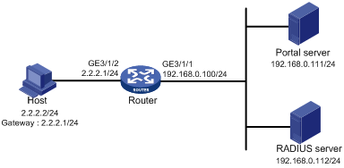
Restrictions and guidelines
To enable the router to redirect HTTPS packets, specify the HTTPS redirect listening port number on the router by using the http-redirect https-port command. For more information about this configuration, see HTTP redirect in Layer 3—IP Services Configuration Guide.
Configuration prerequisites
· Configure IP addresses for the host, router, and servers as shown in Figure 6 and make sure they can reach each other.
· Configure the RADIUS server correctly to provide authentication and accounting functions.
Configuring the portal authentication server on IMC PLAT 5.0
In this example, the portal server runs on IMC PLAT 5.0(E0101) and IMC UAM 5.0(E0101).
1. Configure the portal authentication server:
a. Log in to IMC and click the Service tab.
b. Select User Access Manager > Portal Service Management > Server from the navigation tree to open the portal server configuration page, as shown in Figure 7.
c. Configure the portal server parameters as needed.
This example uses the default settings.
d. Click OK.
Figure 7 Portal server configuration
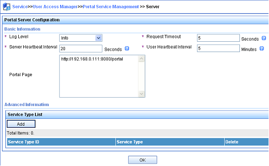
2. Configure the IP address group:
a. Select User Access Manager > Portal Service Management > IP Group from the navigation tree to open the portal IP address group configuration page.
b. Click Add to open the page as shown in Figure 8.
c. Enter the IP group name.
d. Enter the start IP address and end IP address of the IP group.
Make sure the host IP address is in the IP group.
e. Select a service group.
This example uses the default group Ungrouped.
f. Select Normal from the Action list.
g. Click OK.
Figure 8 Adding an IP address group

3. Add a portal device:
a. Select User Access Manager > Portal Service Management > Device from the navigation tree to open the portal device configuration page.
b. Click Add to open the page as shown in Figure 9.
c. Enter the device name NAS.
d. Enter the IP address of the router's interface connected to the host.
e. Enter the key, which must be the same as that configured on the router.
f. Set whether to enable IP address reallocation.
This example uses direct portal authentication, and therefore select No from the Reallocate IP list.
g. Select whether to support server heartbeat and user heartbeat functions.
In this example, select No for both Support Server Heartbeat and Support User Heartbeat.
h. Click OK.
Figure 9 Adding a portal device
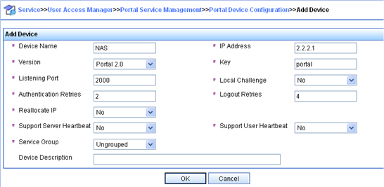
4. Associate the portal device with the IP address group:
a. As shown in Figure 10, click the icon in the Port Group Information Management column of device NAS to open the port group configuration page.
b. Click Add to open the page as shown in Figure 11.
c. Enter the port group name.
d. Select the configured IP address group.
The IP address used by the user to access the network must be within this IP address group.
e. Use the default settings for other parameters.
f. Click OK.
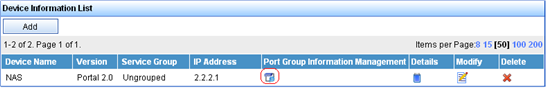
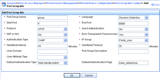
5. Select User Access Manager > Service Parameters > Validate System Configuration from the navigation tree to validate the configurations.
Configuring the router
1. Configure a RADIUS scheme:
# Create a RADIUS scheme named rs1 and enter its view.
<Router> system-view
[Router] radius scheme rs1
# Specify the primary authentication server and primary accounting server, and configure the keys for communication with the servers.
[Router-radius-rs1] primary authentication 192.168.0.112
[Router-radius-rs1] primary accounting 192.168.0.112
[Router-radius-rs1] key authentication simple radius
[Router-radius-rs1] key accounting simple radius
# Exclude the ISP domain name from the username sent to the RADIUS server.
[Router-radius-rs1] user-name-format without-domain
[Router-radius-rs1] quit
# Enable RADIUS session control.
[Router] radius session-control enable
2. Configure an authentication domain:
# Create an ISP domain named dm1 and enter its view.
[Router] domain name dm1
# Configure AAA methods for the ISP domain.
[Router-isp-dm1] authentication portal radius-scheme rs1
[Router-isp-dm1] authorization portal radius-scheme rs1
[Router-isp-dm1] accounting portal radius-scheme rs1
[Router-isp-dm1] quit
# Configure domain dm1 as the default ISP domain. If a user enters the username without the ISP domain name at login, the authentication and accounting methods of the default domain are used for the user.
[Router] domain default enable dm1
3. Configure portal authentication:
# Configure a portal authentication server.
[Router] portal server newpt
[Router-portal-server-newpt] ip 192.168.0.111 key simple portal
[Router-portal-server-newpt] port 50100
[Router-portal-server-newpt] quit
# Configure a portal Web server.
[Router] portal web-server newpt
[Router-portal-websvr-newpt] url http://192.168.0.111:8080/portal
[Router-portal-websvr-newpt] quit
# Specify the HTTPS redirect listening port number.
[Router] http-redirect https-port 8888
# Enable direct portal authentication on GigabitEthernet 3/1/2.
[Router] interface gigabitethernet 3/1/2
[Router–GigabitEthernet3/1/2] portal enable method direct
# Reference the portal Web server newpt on GigabitEthernet 3/1/2.
[Router–GigabitEthernet3/1/2] portal apply web-server newpt
# Configure the BAS-IP as 2.2.2.1 for portal packets sent from GigabitEthernet 3/1/2 to the portal authentication server.
[Router–GigabitEthernet3/1/2] portal bas-ip 2.2.2.1
[Router–GigabitEthernet3/1/2] quit
Verifying the configuration
# Verify that the portal configuration has taken effect.
[Router] display portal interface gigabitethernet 3/1/2
Portal information of GigabitEthernet3/1/2
NAS-ID profile: Not configured
Authorization : Strict checking
ACL : Disabled
User profile : Disabled
IPv4:
Portal status: Enabled
Portal authentication method: Direct
Portal web server: newpt
Portal mac-trigger-server: Not configured
Authentication domain: Not configured
Pre-auth policy: Not configured
User-dhcp-only: Disabled
Pre-auth IP pool: Not configured
Max Portal users: Not configured
Bas-ip: 2.2.2.1
User detection: Not configured
Action for server detection:
Server type Server name Action
-- -- --
Layer3 source network:
IP address Mask
IPv6:
Portal status: Disabled
Portal authentication method: Disabled
Portal web server: Not configured
Portal mac-trigger-server: Not configured
Authentication domain: Not configured
Pre-auth policy: Not configured
User-dhcp-only: Disabled
Pre-auth IP pool: Not configured
Max Portal users: Not configured
Bas-ipv6: Not configured
User detection: Not configured
Action for server detection:
Server type Server name Action
-- -- --
Layer3 source network:
IP address Prefix length
A user can perform portal authentication by using the H3C iNode client or through a Web browser. Before passing the authentication, the user can access only the authentication page http://192.168.0.111:8080/portal. All Web requests from the user will be redirected to the authentication page. After passing the authentication, the user can access other network resources.
# After the user passes authentication, use the following command to display information about the portal user.
[Router] display portal user interface gigabitethernet 3/1/2
Total portal users: 1
Username: abc
Portal server: newpt
State: Online
VPN instance: N/A
MAC IP VLAN Interface
0015-e9a6-7cfe 2.2.2.2 -- GigabitEthernet3/1/2
Authorization information:
DHCP IP pool: N/A
User profile: N/A
Session group profile: N/A
Inbound CAR: N/A
Outbound CAR: N/A
Inbound priority: N/A
Outbound priority: N/A
ACL number: N/A
Inbound CAR: N/A
Outbound CAR: N/A
Inbound priority: N/A
Outbound priority: N/A
Example: Configuring cross-subnet portal authentication
Network configuration
As shown in Figure 12, Router A supports portal authentication. The host accesses Router A through Router B. A portal server acts as both a portal authentication server and a portal Web server. A RADIUS server acts as the authentication/accounting server.
Configure Router A for cross-subnet portal authentication. Before passing the authentication, the host can access only the portal server. After passing the authentication, the user can access other network resources.
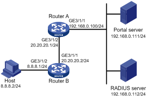
Configuration prerequisites and guidelines
· Configure IP addresses for the router and servers as shown in Figure 12 and make sure the host, router, and servers can reach each other.
· Configure the RADIUS server correctly to provide authentication and accounting functions.
· Make sure the IP address of the portal device added on the portal authentication server is the IP address (20.20.20.1) of the router's interface connecting the host. The IP address group associated with the portal device is the subnet of the host (8.8.8.0/24).
· To enable Router A to redirect HTTPS packets, specify the HTTPS redirect listening port number on Router A by using the http-redirect https-port command. For more information about this configuration, see HTTP redirect in Layer 3—IP Services Configuration Guide.
Procedure
Perform the following tasks on Router A.
1. Configure a RADIUS scheme:
# Create a RADIUS scheme named rs1 and enter its view.
<RouterA> system-view
[RouterA] radius scheme rs1
# Specify the primary authentication server and primary accounting server, and configure the keys for communication with the servers.
[RouterA-radius-rs1] primary authentication 192.168.0.112
[RouterA-radius-rs1] primary accounting 192.168.0.112
[RouterA-radius-rs1] key authentication simple radius
[RouterA-radius-rs1] key accounting simple radius
# Exclude the ISP domain name from the username sent to the RADIUS server.
[RouterA-radius-rs1] user-name-format without-domain
[RouterA-radius-rs1] quit
# Enable RADIUS session control.
[RouterA] radius session-control enable
2. Configure an authentication domain:
# Create an ISP domain named dm1 and enter its view.
[RouterA] domain name dm1
# Configure AAA methods for the ISP domain.
[RouterA-isp-dm1] authentication portal radius-scheme rs1
[RouterA-isp-dm1] authorization portal radius-scheme rs1
[RouterA-isp-dm1] accounting portal radius-scheme rs1
[RouterA-isp-dm1] quit
# Configure domain dm1 as the default ISP domain. If a user enters the username without the ISP domain name at login, the authentication and accounting methods of the default domain are used for the user.
[RouterA] domain default enable dm1
3. Configure portal authentication:
# Configure a portal authentication server.
[RouterA] portal server newpt
[RouterA-portal-server-newpt] ip 192.168.0.111 key simple portal
[RouterA-portal-server-newpt] port 50100
[RouterA-portal-server-newpt] quit
# Configure a portal Web server.
[Router] portal web-server newpt
[RouterA-portal-websvr-newpt] url http://192.168.0.111:8080/portal
[RouterA-portal-websvr-newpt] quit
# Specify the HTTPS redirect listening port number.
[RouterA] http-redirect https-port 8888
# Enable cross-subnet portal authentication on GigabitEthernet 3/1/2.
[RouterA] interface gigabitethernet 3/1/2
[RouterA–GigabitEthernet3/1/2] portal enable method layer3
# Reference the portal Web server newpt on GigabitEthernet 3/1/2.
[RouterA–GigabitEthernet3/1/2] portal apply web-server newpt
# Configure the BAS-IP as 20.20.20.1 for portal packets sent from GigabitEthernet 3/1/2 to the portal authentication server.
[RouterA–GigabitEthernet3/1/2] portal bas-ip 20.20.20.1
[RouterA–GigabitEthernet3/1/2] quit
On Router B, configure a default route to subnet 192.168.0.0/24, specifying the next hop address as 20.20.20.1. (Details not shown.)
Verifying the configuration
# Verify that the portal configuration has taken effect.
[RouterA] display portal interface gigabitethernet 3/1/2
Portal information of GigabitEthernet3/1/2
NAS-ID profile: Not configured
Authorization : Strict checking
ACL : Disabled
User profile : Disabled
IPv4:
Portal status: Enabled
Portal authentication method: Layer3
Portal web server: newpt
Portal mac-trigger-server: Not configured
Authentication domain: Not configured
Pre-auth policy: Not configured
User-dhcp-only: Disabled
Pre-auth IP pool: Not configured
Max Portal users: Not configured
Bas-ip: 20.20.20.1
User detection: Not configured
Action for server detection:
Server type Server name Action
-- -- --
Layer3 source network:
IP address Mask
IPv6:
Portal status: Disabled
Portal authentication method: Disabled
Portal web server: Not configured
Portal mac-trigger-server: Not configured
Authentication domain: Not configured
Pre-auth policy: Not configured
User-dhcp-only: Disabled
Pre-auth IP pool: Not configured
Max Portal users: Not configured
Bas-ipv6: Not configured
User detection: Not configured
Action for server detection:
Server type Server name Action
-- -- --
Layer3 source network:
IP address Prefix length
A user can perform portal authentication by using the H3C iNode client or through a Web browser. Before passing the authentication, the user can access only the authentication page http://192.168.0.111:8080/portal. All Web requests from the user will be redirected to the authentication page. After passing the authentication, the user can access other network resources.
# After the user passes authentication, use the following command to display information about the portal user.
[RouterA] display portal user interface gigabitethernet 3/1/2
Total portal users: 1
Username: abc
Portal server: newpt
State: Online
VPN instance: N/A
MAC IP VLAN Interface
0000-0000-0000 8.8.8.2 -- GigabitEthernet3/1/2
Authorization information:
DHCP IP pool: N/A
User profile: N/A
Session group profile: N/A
ACL number: N/A
Inbound CAR: N/A
Outbound CAR: N/A
Inbound priority: N/A
Outbound priority: N/A
Example: Configuring extended direct portal authentication
Network configuration
As shown in Figure 13, the host is directly connected to the router (the access device). The host is assigned a public IP address either manually or through DHCP. A portal server acts as both a portal authentication server and a portal Web server. A RADIUS server acts as the authentication/accounting server.
Configure extended direct portal authentication. If the host fails security check after passing identity authentication, it can access only subnet 192.168.0.0/24. After passing security check, the host can access other network resources.
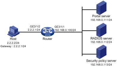
Restrictions and guidelines
To enable the router to redirect HTTPS packets, specify the HTTPS redirect listening port number on the router by using the http-redirect https-port command. For more information about this configuration, see HTTP redirect in Layer 3—IP Services Configuration Guide.
Configuration prerequisites
· Configure IP addresses for the host, router, and servers as shown in Figure 13 and make sure they can reach each other.
· Configure the RADIUS server correctly to provide authentication and accounting functions.
Procedure
Perform the following tasks on the router.
1. Configure a RADIUS scheme:
# Create a RADIUS scheme named rs1 and enter its view.
<Router> system-view
[Router] radius scheme rs1
# Specify the primary authentication server and primary accounting server, and configure the keys for communication with the servers.
[Router-radius-rs1] primary authentication 192.168.0.112
[Router-radius-rs1] primary accounting 192.168.0.112
[Router-radius-rs1] key accounting simple radius
[Router-radius-rs1] key authentication simple radius
[Router-radius-rs1] user-name-format without-domain
# Enable RADIUS session control.
[Router] radius session-control enable
# Specify a session-control client with IP address 192.168.0.112 and shared key 12345 in plain text.
[Router] radius session-control client ip 192.168.0.112 key simple 12345
2. Configure an authentication domain:
# Create an ISP domain named dm1 and enter its view.
[Router] domain name dm1
# Configure AAA methods for the ISP domain.
[Router-isp-dm1] authentication portal radius-scheme rs1
[Router-isp-dm1] authorization portal radius-scheme rs1
[Router-isp-dm1] accounting portal radius-scheme rs1
[Router-isp-dm1] quit
# Configure domain dm1 as the default ISP domain. If a user enters the username without the ISP domain name at login, the authentication and accounting methods of the default domain are used for the user.
[Router] domain default enable dm1
3. Configure ACL 3000 as the isolation ACL and ACL 3001 as the security ACL.
[Router] acl advanced 3000
[Router-acl-ipv4-adv-3000] rule permit ip destination 192.168.0.0 0.0.0.255
[Router-acl-ipv4-adv-3000] rule deny ip
[Router-acl-ipv4-adv-3000] quit
[Router] acl advanced 3001
[Router-acl-ipv4-adv-3001] rule permit ip
[Router-acl-ipv4-adv-3001] quit
|
|
NOTE: Make sure you specify ACL 3000 as the isolation ACL and ACL 3001 as the security ACL on the security policy server. |
4. Configure portal authentication:
# Configure a portal authentication server.
[Router] portal server newpt
[Router-portal-server-newpt] ip 192.168.0.111 key simple portal
[Router-portal-server-newpt] port 50100
[Router-portal-server-newpt] quit
# Configure a portal Web server.
[Router] portal web-server newpt
[Router-portal-websvr-newpt] url http://192.168.0.111:8080/portal
[Router-portal-websvr-newpt] quit
# Specify the HTTPS redirect listening port number.
[Router] http-redirect https-port 8888
# Enable direct portal authentication on GigabitEthernet 3/1/2.
[Router] interface gigabitethernet 3/1/2
[Router–GigabitEthernet3/1/2] portal enable method direct
# Reference the portal Web server newpt on GigabitEthernet 3/1/2.
[Router–GigabitEthernet3/1/2] portal apply web-server newpt
# Configure the BAS-IP as 2.2.2.1 for portal packets sent from GigabitEthernet 3/1/2 to the portal authentication server.
[Router–GigabitEthernet3/1/2] portal bas-ip 2.2.2.1
[Router–GigabitEthernet3/1/2] quit
Verifying the configuration
# Verify that the portal configuration has taken effect.
[Router] display portal interface gigabitethernet 3/1/2
Portal information of GigabitEthernet3/1/2
NAS-ID profile: Not configured
Authorization : Strict checking
ACL : Disabled
User profile : Disabled
IPv4:
Portal status: Enabled
Portal authentication method: Direct
Portal web server: newpt
Portal mac-trigger-server: Not configured
Authentication domain: Not configured
Pre-auth policy: Not configured
User-dhcp-only: Disabled
Pre-auth IP pool: Not configured
Max Portal users: Not configured
Bas-ip: 2.2.2.1
User detection: Not configured
Action for server detection:
Server type Server name Action
-- -- --
Layer3 source network:
IP address Mask
IPv6:
Portal status: Disabled
Portal authentication method: Disabled
Portal web server: Not configured
Portal mac-trigger-server: Not configured
Authentication domain: Not configured
Pre-auth policy: Not configured
User-dhcp-only: Disabled
Pre-auth IP pool: Not configured
Max Portal users: Not configured
Bas-ipv6: Not configured
User detection: Not configured
Action for server detection:
Server type Server name Action
-- -- --
Layer3 source network:
IP address Prefix length
Before passing portal authentication, a user that uses the H3C iNode client can access only the authentication page http://192.168.0.111:8080/portal. All Web requests from the user will be redirected to the authentication page.
· The user can access the resources permitted by ACL 3000 after passing only identity authentication.
· The user can access network resources permitted by ACL 3001 after passing both identity authentication and security check.
# After the user passes identity authentication and security check, use the following command to display information about the portal user.
[Router] display portal user interface gigabitethernet 3/1/2
Total portal users: 1
Username: abc
Portal server: newpt
State: Online
VPN instance: N/A
MAC IP VLAN Interface
0015-e9a6-7cfe 2.2.2.2 -- GigabitEthernet3/1/2
Authorization information:
DHCP IP pool: N/A
User profile: N/A
Session group profile: N/A
ACL number: 3001 (active)
Inbound CAR: N/A
Outbound CAR: N/A
Inbound priority: N/A
Outbound priority: N/A
Example: Configuring extended re-DHCP portal authentication
Network configuration
As shown in Figure 14, the host is directly connected to the router (the access device). The host obtains an IP address through the DHCP server. A portal server acts as both a portal authentication server and a portal Web server. A RADIUS server acts as the authentication/accounting server.
Configure extended re-DHCP portal authentication. Before passing portal authentication, the host is assigned a private IP address. After passing portal identity authentication, the host obtains a public IP address and accepts security check. If the host fails the security check, it can access only subnet 192.168.0.0/24. After passing the security check, the host can access other network resources.
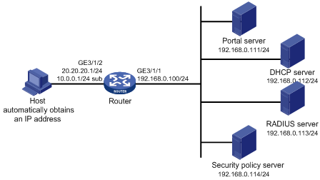
Configuration prerequisites and guidelines
· Configure IP addresses for the router and servers as shown in Figure 14 and make sure the host, router, and servers can reach each other.
· Configure the RADIUS server correctly to provide authentication and accounting functions.
· For re-DHCP portal authentication, configure a public address pool (20.20.20.0/24) and a private address pool (10.0.0.0/24) on the DHCP server. (Details not shown.)
· For re-DHCP portal authentication:
¡ The router must be configured as a DHCP relay agent.
¡ The portal-enabled interface must be configured with a primary IP address (a public IP address) and a secondary IP address (a private IP address).
For information about DHCP relay agent configuration, see Layer 3—IP Services Configuration Guide.
· Make sure the IP address of the portal device added on the portal server is the public IP address (20.20.20.1) of the router's interface connecting the host. The private IP address range for the IP address group associated with the portal device is the private subnet 10.0.0.0/24 where the host resides. The public IP address range for the IP address group is the public subnet 20.20.20.0/24.
· To enable the router to redirect HTTPS packets, specify the HTTPS redirect listening port number on the router by using the http-redirect https-port command. For more information about this configuration, see HTTP redirect in Layer 3—IP Services Configuration Guide.
Procedure
Perform the following tasks on the router.
1. Configure a RADIUS scheme:
# Create a RADIUS scheme named rs1 and enter its view.
<Router> system-view
[Router] radius scheme rs1
# Specify the primary authentication server and primary accounting server, and configure the keys for communication with the servers.
[Router-radius-rs1] primary authentication 192.168.0.113
[Router-radius-rs1] primary accounting 192.168.0.113
[Router-radius-rs1] key authentication simple radius
[Router-radius-rs1] key accounting simple radius
[Router-radius-rs1] user-name-format without-domain
# Enable RADIUS session control.
[Router] radius session-control enable
# Specify a session-control client with IP address 192.168.0.113 and shared key 12345 in plain text.
[Router] radius session-control client ip 192.168.0.113 key simple 12345
2. Configure an authentication domain:
# Create an ISP domain named dm1 and enter its view.
[Router] domain name dm1
# Configure AAA methods for the ISP domain.
[Router-isp-dm1] authentication portal radius-scheme rs1
[Router-isp-dm1] authorization portal radius-scheme rs1
[Router-isp-dm1] accounting portal radius-scheme rs1
[Router-isp-dm1] quit
# Configure domain dm1 as the default ISP domain. If a user enters the username without the ISP domain name at login, the authentication and accounting methods of the default domain are used for the user.
[Router] domain default enable dm1
3. Configure ACL 3000 as the isolation ACL and ACL 3001 as the security ACL.
[Router] acl advanced 3000
[Router-acl-ipv4-adv-3000] rule permit ip destination 192.168.0.0 0.0.0.255
[Router-acl-ipv4-adv-3000] rule deny ip
[Router-acl-ipv4-adv-3000] quit
[Router] acl advanced 3001
[Router-acl-ipv4-adv-3001] rule permit ip
[Router-acl-ipv4-adv-3001] quit
|
|
NOTE: Make sure you specify ACL 3000 as the isolation ACL and ACL 3001 as the security ACL on the security policy server. |
4. Configure DHCP relay and authorized ARP:
|
|
NOTE: For portal users to come online, do not enable recording client information in relay entries on the DHCP relay agent by using the dhcp relay client-information record command. |
# Configure DHCP relay.
[Router] dhcp enable
[Router] interface gigabitethernet 3/1/2
[Router–GigabitEthernet3/1/2] ip address 20.20.20.1 255.255.255.0
[Router–GigabitEthernet3/1/2] ip address 10.0.0.1 255.255.255.0 sub
[Router-GigabitEthernet3/1/2] dhcp select relay
[Router-GigabitEthernet3/1/2] dhcp relay server-address 192.168.0.112
# Enable authorized ARP.
[Router-GigabitEthernet3/1/2] arp authorized enable
[Router-GigabitEthernet3/1/2] quit
5. Configure portal authentication:
# Configure a portal authentication server.
[Router] portal server newpt
[Router-portal-server-newpt] ip 192.168.0.111 key simple portal
[Router-portal-server-newpt] port 50100
[Router-portal-server-newpt] quit
# Configure a portal Web server.
[Router] portal web-server newpt
[Router-portal-websvr-newpt] url http://192.168.0.111:8080/portal
[Router-portal-websvr-newpt] quit
# Specify the HTTPS redirect listening port number.
[Router] http-redirect https-port 8888
# Enable re-DHCP portal authentication on GigabitEthernet 3/1/2.
[Router] interface gigabitethernet 3/1/2
[Router-GigabitEthernet3/1/2] portal enable method redhcp
# Reference the portal Web server newpt on GigabitEthernet 3/1/2.
[Router–GigabitEthernet3/1/2] portal apply web-server newpt
# Configure the BAS-IP as 20.20.20.1 for portal packets sent from GigabitEthernet 3/1/2 to the portal authentication server.
[Router–GigabitEthernet3/1/2] portal bas-ip 20.20.20.1
[Router–GigabitEthernet3/1/2] quit
Verifying the configuration
# Verify that the portal configuration has taken effect.
[Router] display portal interface gigabitethernet 3/1/2
Portal information of GigabitEthernet3/1/2
NAS-ID profile: Not configured
Authorization : Strict checking
ACL : Disabled
User profile : Disabled
IPv4:
Portal status: Enabled
Portal authentication method: Redhcp
Portal web server: newpt
Portal mac-trigger-server: Not configured
Authentication domain: Not configured
Pre-auth policy: Not configured
User-dhcp-only: Disabled
Pre-auth IP pool: Not configured
Max Portal users: Not configured
Bas-ip: 20.20.20.1
User detection: Not configured
Action for server detection:
Server type Server name Action
-- -- --
Layer3 source network:
IP address Mask
IPv6:
Portal status: Disabled
Portal authentication method: Disabled
Portal web server: Not configured
Portal mac-trigger-server: Not configured
Authentication domain: Not configured
Pre-auth policy: Not configured
User-dhcp-only: Disabled
Pre-auth IP pool: Not configured
Max Portal users: Not configured
Bas-ipv6: Not configured
User detection: Not configured
Action for server detection:
Server type Server name Action
-- -- --
Layer3 source network:
IP address Prefix length
Before passing portal authentication, a user that uses the H3C iNode client can access only the authentication page http://192.168.0.111:8080/portal. All Web requests from the user will be redirected to the authentication page.
· The user can access the resources permitted by ACL 3000 after passing only identity authentication.
· The user can access network resources permitted by ACL 3001 after passing both identity authentication and security check.
# After the user passes identity authentication and security check, use the following command to display information about the portal user.
[Router] display portal user interface gigabitethernet 3/1/2
Total portal users: 1
Username: abc
Portal server: newpt
State: Online
VPN instance: N/A
MAC IP VLAN Interface
0015-e9a6-7cfe 20.20.20.2 -- GigabitEthernet3/1/2
Authorization information:
DHCP IP pool: N/A
User profile: N/A
Session group profile: N/A
ACL number: 3001 (active)
Inbound CAR: N/A
Outbound CAR: N/A
Inbound priority: N/A
Outbound priority: N/A
Example: Configuring extended cross-subnet portal authentication
Network configuration
As shown in Figure 15, Router A supports portal authentication. The host accesses Router A through Router B. A portal server acts as both a portal authentication server and a portal Web server. A RADIUS server acts as the authentication/accounting server.
Configure Router A for extended cross-subnet portal authentication. Before passing portal authentication, the host can access only the portal server. After passing portal identity authentication, the host accepts security check. If the host fails the security check it can access only the subnet 192.168.0.0/24. After passing the security check, the host can access other network resources.
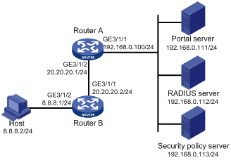
Configuration prerequisites and guidelines
· Configure IP addresses for the router and servers as shown in Figure 15 and make sure the host, router, and servers can reach each other.
· Configure the RADIUS server correctly to provide authentication and accounting functions.
· Make sure the IP address of the portal device added on the portal server is the IP address (20.20.20.1) of the router's interface connecting the host. The IP address group associated with the portal device is the subnet of the host (8.8.8.0/24).
· To enable Router A to redirect HTTPS packets, specify the HTTPS redirect listening port number on Router A by using the http-redirect https-port command. For more information about this configuration, see HTTP redirect in Layer 3—IP Services Configuration Guide.
Procedure
Perform the following tasks on Router A.
1. Configure a RADIUS scheme:
# Create a RADIUS scheme named rs1 and enter its view.
<RouterA> system-view
[RouterA] radius scheme rs1
# Specify the primary authentication server and primary accounting server, and configure the keys for communication with the servers.
[RouterA-radius-rs1] primary authentication 192.168.0.112
[RouterA-radius-rs1] primary accounting 192.168.0.112
[RouterA-radius-rs1] key authentication simple radius
[RouterA-radius-rs1] key accounting simple radius
[RouterA-radius-rs1] user-name-format without-domain
# Enable RADIUS session control.
[RouterA] radius session-control enable
# Specify a session-control client with IP address 192.168.0.112 and shared key 12345 in plain text.
[RouterA] radius session-control client ip 192.168.0.112 key simple 12345
2. Configure an authentication domain:
# Create an ISP domain named dm1 and enter its view.
[RouterA] domain name dm1
# Configure AAA methods for the ISP domain.
[RouterA-isp-dm1] authentication portal radius-scheme rs1
[RouterA-isp-dm1] authorization portal radius-scheme rs1
[RouterA-isp-dm1] accounting portal radius-scheme rs1
[RouterA-isp-dm1] quit
# Configure domain dm1 as the default ISP domain. If a user enters the username without the ISP domain name at login, the authentication and accounting methods of the default domain are used for the user.
[RouterA] domain default enable dm1
3. Configure ACL 3000 as the isolation ACL and ACL 3001 as the security ACL.
[RouterA] acl advanced 3000
[RouterA-acl-ipv4-adv-3000] rule permit ip destination 192.168.0.0 0.0.0.255
[RouterA-acl-ipv4-adv-3000] rule deny ip
[RouterA-acl-ipv4-adv-3000] quit
[RouterA] acl advanced 3001
[RouterA-acl-ipv4-adv-3001] rule permit ip
[RouterA-acl-ipv4-adv-3001] quit
|
|
NOTE: Make sure you specify ACL 3000 as the isolation ACL and ACL 3001 as the security ACL on the security policy server. |
4. Configure portal authentication:
# Configure a portal authentication server.
[RouterA] portal server newpt
[RouterA-portal-server-newpt] ip 192.168.0.111 key simple portal
[RouterA-portal-server-newpt] port 50100
[RouterA-portal-server-newpt] quit
# Configure a portal Web server.
[Router] portal web-server newpt
[RouterA-portal-websvr-newpt] url http://192.168.0.111:8080/portal
[RouterA-portal-websvr-newpt] quit
# Specify the HTTPS redirect listening port number.
[RouterA] http-redirect https-port 8888
# Enable cross-subnet portal authentication on GigabitEthernet 3/1/2.
[RouterA] interface gigabitethernet 3/1/2
[RouterA–GigabitEthernet3/1/2] portal enable method layer3
# Reference the portal Web server newpt on GigabitEthernet 3/1/2.
[RouterA–GigabitEthernet3/1/2] portal apply web-server newpt
# Configure the BAS-IP as 20.20.20.1 for portal packets sent from GigabitEthernet 3/1/2 to the portal authentication server.
[RouterA–GigabitEthernet3/1/2] portal bas-ip 20.20.20.1
[RouterA–GigabitEthernet3/1/2] quit
Verifying the configuration
# Verify that the portal configuration has taken effect.
[RouterA] display portal interface gigabitethernet 3/1/2
Portal information of GigabitEthernet3/1/2
NAS-ID profile: Not configured
Authorization : Strict checking
ACL : Disabled
User profile : Disabled
IPv4:
Portal status: Enabled
Portal authentication method: Layer3
Portal web server: newpt
Portal mac-trigger-server: Not configured
Authentication domain: Not configured
Pre-auth policy: Not configured
User-dhcp-only: Disabled
Pre-auth IP pool: Not configured
Max Portal users: Not configured
Bas-ip: 20.20.20.1
User detection: Not configured
Action for server detection:
Server type Server name Action
-- -- --
Layer3 source network:
IP address Mask
IPv6:
Portal status: Disabled
Portal authentication method: Disabled
Portal web server: Not configured
Portal mac-trigger-server: Not configured
Authentication domain: Not configured
Pre-auth policy: Not configured
User-dhcp-only: Disabled
Pre-auth IP pool: Not configured
Max Portal users: Not configured
Bas-ipv6: Not configured
User detection: Not configured
Action for server detection:
Server type Server name Action
-- -- --
Layer3 source network:
IP address Prefix length
Before passing portal authentication, a user that uses the H3C iNode client can access only the authentication page http://192.168.0.111:8080/portal. All Web requests from the user are redirected to the authentication page.
· The user can access the resources permitted by ACL 3000 after passing only identity authentication.
· The user can access network resources permitted by ACL 3001 after passing both identity authentication and security check.
# After the user passes identity authentication and security check, use the following command to display information about the portal user.
[RouterA] display portal user interface gigabitethernet 3/1/2
Total portal users: 1
Username: abc
Portal server: newpt
State: Online
VPN instance: N/A
MAC IP VLAN Interface
0015-e9a6-7cfe 8.8.8.2 -- GigabitEthernet3/1/2
Authorization information:
DHCP IP pool: N/A
User profile: N/A
Session group profile: N/A
ACL number: 3001 (active)
Inbound CAR: N/A
Outbound CAR: N/A
Inbound priority: N/A
Outbound priority: N/A
Example: Configuring portal server detection and portal user synchronization
Network configuration
As shown in Figure 16, the host is directly connected to the router (the access device). The host is assigned a public IP address either manually or through DHCP. A portal server acts as both a portal authentication server and a portal Web server. A RADIUS server acts as the authentication/accounting server.
Configure direct portal authentication on the router, so the host can access only the portal server before passing the authentication and access other network resources after passing the authentication.
Configure the router to do the following:
· Detect the reachability state of the portal authentication server.
· Send log messages upon state changes.
· Disable portal authentication when the authentication server is unreachable.
· Synchronize portal user information with the portal server periodically.
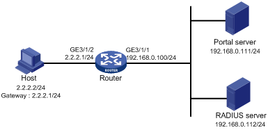
Configuration prerequisites and guidelines
· Configure IP addresses for the router and servers as shown in Figure 16 and make sure the host, router, and servers can reach each other.
· Configure the RADIUS server correctly to provide authentication and accounting functions.
· To enable the router to redirect HTTPS packets, specify the HTTPS redirect listening port number on the router by using the http-redirect https-port command. For more information about this configuration, see HTTP redirect in Layer 3—IP Services Configuration Guide.
Configuring the portal authentication server on IMC PLAT 5.0
In this example, the portal server runs on IMC PLAT 5.0(E0101) and IMC UAM 5.0(E0101).
1. Configure the portal authentication server:
a. Log in to IMC and click the Service tab.
b. Select User Access Manager > Portal Service Management > Server from the navigation tree to open the portal server configuration page, as shown in Figure 17.
c. Configure the portal server heartbeat interval and user heartbeat interval.
d. Use the default settings for other parameters.
e. Click OK.
Figure 17 Portal authentication server configuration
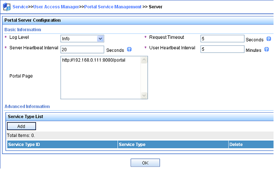
2. Configure the IP address group:
a. Select User Access Manager > Portal Service Management > IP Group from the navigation tree to open the portal IP address group configuration page.
b. Click Add to open the page as shown in Figure 18.
c. Enter the IP group name.
d. Enter the start IP address and end IP address of the IP group.
Make sure the host IP address is in the IP group.
e. Select a service group.
This example uses the default group Ungrouped.
f. Select Normal from the Action list.
g. Click OK.
Figure 18 Adding an IP address group
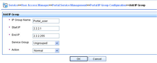
3. Add a portal device:
a. Select User Access Manager > Portal Service Management > Device from the navigation tree to open the portal device configuration page.
b. Click Add to open the page as shown in Figure 19.
c. Enter the device name NAS.
d. Enter the IP address of the router's interface connected to the host.
e. Enter the key, which must be the same as that configured on the router.
f. Set whether to enable IP address reallocation.
This example uses direct portal authentication, and therefore select No from the Reallocate IP list.
g. Select whether to support server heartbeat and user heartbeat functions.
In this example, select Yes for both Support Server Heartbeat and Support User Heartbeat.
h. Click OK.
Figure 19 Adding a portal device
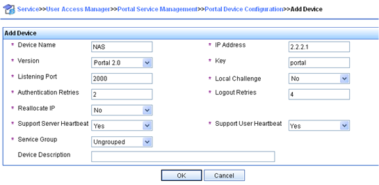
4. Associate the portal device with the IP address group:
a. As shown in Figure 20, click the icon in the Port Group Information Management column of device NAS to open the port group configuration page.
b. Click Add to open the page as shown in Figure 21.
c. Enter the port group name.
d. Select the configured IP address group.
The IP address used by the user to access the network must be within this IP address group.
e. Use the default settings for other parameters.
f. Click OK.
5. Select User Access Manager > Service Parameters > Validate System Configuration from the navigation tree to validate the configurations.
Configuring the router
1. Configure a RADIUS scheme:
# Create a RADIUS scheme named rs1 and enter its view.
<Router> system-view
[Router] radius scheme rs1
# Specify the primary authentication server and primary accounting server, and configure the keys for communication with the servers.
[Router-radius-rs1] primary authentication 192.168.0.112
[Router-radius-rs1] primary accounting 192.168.0.112
[Router-radius-rs1] key authentication simple radius
[Router-radius-rs1] key accounting simple radius
# Exclude the ISP domain name from the username sent to the RADIUS server.
[Router-radius-rs1] user-name-format without-domain
[Router-radius-rs1] quit
# Enable RADIUS session control.
[Router] radius session-control enable
2. Configure an authentication domain:
# Create an ISP domain named dm1 and enter its view.
[Router] domain name dm1
# Configure AAA methods for the ISP domain.
[Router-isp-dm1] authentication portal radius-scheme rs1
[Router-isp-dm1] authorization portal radius-scheme rs1
[Router-isp-dm1] accounting portal radius-scheme rs1
[Router-isp-dm1] quit
# Configure domain dm1 as the default ISP domain. If a user enters the username without the ISP domain name at login, the authentication and accounting methods of the default domain are used for the user.
[Router] domain default enable dm1
3. Configure portal authentication:
# Configure a portal authentication server.
[Router] portal server newpt
[Router-portal-server-newpt] ip 192.168.0.111 key simple portal
[Router-portal-server-newpt] port 50100
# Configure reachability detection of the portal authentication server: set the server detection interval to 40 seconds, and send log messages upon reachability status changes.
[Router-portal-server-newpt] server-detect timeout 40 log
|
|
NOTE: The value of timeout must be greater than or equal to the portal server heartbeat interval. |
# Configure portal user synchronization with the portal authentication server, and set the synchronization detection interval to 600 seconds.
[Router-portal-server-newpt] user-sync timeout 600
[Router-portal-server-newpt] quit
|
|
NOTE: The value of timeout must be greater than or equal to the portal user heartbeat interval. |
# Configure a portal Web server.
[Router] portal web-server newpt
[Router-portal-websvr-newpt] url http://192.168.0.111:8080/portal
[Router-portal-websvr-newpt] quit
# Specify the HTTPS redirect listening port number.
[Router] http-redirect https-port 8888
# Enable direct portal authentication on GigabitEthernet 3/1/2.
[Router] interface gigabitethernet 3/1/2
[Router–GigabitEthernet3/1/2] portal enable method direct
# Enable portal fail-permit for the portal authentication server newpt.
[Router–GigabitEthernet3/1/2] portal fail-permit server newpt
# Reference the portal Web server newpt on GigabitEthernet 3/1/2.
[Router–GigabitEthernet3/1/2] portal apply web-server newpt
# Configure the BAS-IP as 2.2.2.1 for portal packets sent from GigabitEthernet 3/1/2 to the portal authentication server.
[Router–GigabitEthernet3/1/2] portal bas-ip 2.2.2.1
[Router–GigabitEthernet3/1/2] quit
Verifying the configuration
# Use the following command to display information about the portal authentication server.
[Router] display portal server newpt
Portal server: newpt
Type : IMC
IP : 192.168.0.111
VPN instance : Not configured
Port : 50100
Server Detection : Timeout 40s Action: log
User synchronization : Timeout 600s
Status : Up
Exclude-attribute : Not configured
Logout-notification : Retry 3 interval 5s
The Up status of the portal authentication server indicates that the portal authentication server is reachable. If the access device detects that the portal authentication server is unreachable, the Status field in the command output displays Down. The access device generates a server unreachable log "Portal server newpt turns down from up." and disables portal authentication on the access interface, so the host can access the external network without authentication.
Example: Configuring cross-subnet portal authentication for MPLS L3VPNs
Network configuration
As shown in Figure 22, the PE device Router A provides portal authentication for the host in VPN 1. A portal server in VPN 3 acts as the portal authentication server, portal Web server, and RADIUS server.
Configure cross-subnet portal authentication on Router A, so the host can access network resources after passing identity authentication.
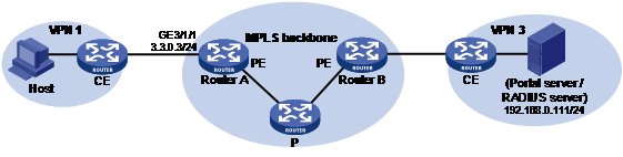
Restrictions and guidelines
To enable Router A to redirect HTTPS packets, specify the HTTPS redirect listening port number on Router A by using the http-redirect https-port command. For more information about this configuration, see HTTP redirect in Layer 3—IP Services Configuration Guide.
Configuration prerequisites
· Before enabling portal authentication, configure MPLS L3VPN and specify VPN targets for VPN 1 and VPN 3 so that VPN 1 and VPN 3 can communicate with each other. This example describes only the access authentication configuration on the user-side PE. For information about MPLS L3VPN configurations, see MPLS Configuration Guide.
· Configure the RADIUS server correctly to provide authentication and accounting functions.
Procedure
Perform the following tasks on Router A.
1. Configure a RADIUS scheme:
# Create a RADIUS scheme named rs1 and enter its view.
<RouterA> system-view
[RouterA] radius scheme rs1
# For the RADIUS scheme, specify the VPN instance that is bound to the interface connected to the portal/RADIUS server. This example uses VPN instance vpn3. (For information about the VPN instance, see the MPLS L3VPN configuration on Router A.)
[RouterA-radius-rs1] vpn-instance vpn3
# Specify the primary authentication server and primary accounting server, and configure the keys for communication with the servers.
[RouterA-radius-rs1] primary authentication 192.168.0.111
[RouterA-radius-rs1] primary accounting 192.168.0.111
[RouterA-radius-rs1] key accounting simple radius
[RouterA-radius-rs1] key authentication simple radius
# Exclude the ISP domain name from the username sent to the RADIUS server.
[RouterA-radius-rs1] user-name-format without-domain
# Specify the source IP address for RADIUS packets to be sent as 3.3.0.3. This address must be the same as that of the portal device specified on the portal authentication server to avoid authentication failures.
[RouterA-radius-rs1] nas-ip 3.3.0.3
[RouterA-radius-rs1] quit
# Enable RADIUS session control.
[RouterA] radius session-control enable
2. Configure an authentication domain:
# Create an ISP domain named dm1 and enter its view.
[RouterA] domain name dm1
# Configure AAA methods for the ISP domain.
[RouterA-isp-dm1] authentication portal radius-scheme rs1
[RouterA-isp-dm1] authorization portal radius-scheme rs1
[RouterA-isp-dm1] accounting portal radius-scheme rs1
[RouterA-isp-dm1] quit
# Configure domain dm1 as the default ISP domain. If a user enters the username without the ISP domain name at login, the authentication and accounting methods of the default domain are used for the user.
[RouterA] domain default enable dm1
3. Configure portal authentication:
# Configure a portal authentication server.
[RouterA] portal server newpt
[RouterA-portal-server-newpt] ip 192.168.0.111 vpn-instance vpn3 key simple portal
[RouterA-portal-server-newpt] port 50100
[RouterA-portal-server-newpt] quit
# Configure a portal Web server.
[RouterA] portal web-server newpt
[RouterA-portal-websvr-newpt] url http://192.168.0.111:8080/portal
[RouterA-portal-websvr-newpt] vpn-instance vpn3
[RouterA-portal-websvr-newpt] quit
# Specify the HTTPS redirect listening port number.
[RouterA] http-redirect https-port 8888
# Enable cross-subnet portal authentication on GigabitEthernet 3/1/1.
[RouterA] interface gigabitethernet 3/1/1
[RouterA–GigabitEthernet3/1/1] portal enable method layer3
# Reference the portal Web server newpt on GigabitEthernet 3/1/1.
[RouterA–GigabitEthernet3/1/1] portal apply web-server newpt
# Configure the BAS-IP as 3.3.0.3 for portal packets sent from GigabitEthernet 3/1/1 to the portal authentication server.
[RouterA–GigabitEthernet3/1/1] portal bas-ip 3.3.0.3
[RouterA–GigabitEthernet3/1/1] quit
Verifying the configuration
# Verify the portal configuration by executing the display portal interface command. (Details not shown.)
# After the user passes authentication, execute the display portal user command to display the portal user information.
[RouterA] display portal user all
Total portal users: 1
Username: abc
Portal server: newpt
State: Online
VPN instance: vpn3
MAC IP VLAN Interface
000d-88f7-c268 3.3.0.1 -- GigabitEthernet3/1/1
Authorization information:
DHCP IP pool: N/A
User profile: N/A
Session group profile: N/A
ACL number: N/A
Inbound CAR: N/A
Outbound CAR: N/A
Inbound priority: N/A
Outbound priority: N/A
Example: Configuring direct portal authentication with a preauthentication policy
Network configuration
As shown in Figure 23, the host is directly connected to the router (the access device). The host is assigned a public IP address through DHCP. A portal server acts as both a portal authentication server and a portal Web server. A RADIUS server acts as the authentication/accounting server.
Configure direct portal authentication, so the host can access only subnet 192.168.0.0/24 before passing the authentication and access other network resources after passing the authentication.
Restrictions and guidelines
To enable the router to redirect HTTPS packets, specify the HTTPS redirect listening port number on the router by using the http-redirect https-port command. For more information about this configuration, see HTTP redirect in Layer 3—IP Services Configuration Guide.
Configuration prerequisites
· Configure IP addresses for the host, router, and servers as shown in Figure 23 and make sure they can reach each other.
· Configure the RADIUS server correctly to provide authentication and accounting functions.
Procedure
Perform the following tasks on the router.
1. Configure a preauthentication IP address pool:
# Configure DHCP address pool pre to assign IP addresses and other configuration parameters to clients on subnet 2.2.2.0/24.
<Router> system-view
[Router] dhcp server ip-pool pre
[Router-dhcp-pool-pre] gateway-list 2.2.2.1
[Router-dhcp-pool-pre] network 2.2.2.0 24
[Router-dhcp-pool-pre] quit
# Enable the DHCP server on GigabitEthernet 3/1/2.
[Router] interface gigabitethernet 3/1/2
[Router–GigabitEthernet3/1/2] dhcp select server
[Router–GigabitEthernet3/1/2] quit
2. Configure a portal preauthentication policy:
# Create a portal preauthentication policy named abc.
[Router] portal pre-auth policy abc
# Specify user attribute ACL 3010 in the portal preauthentication policy.
[Router-pre-auth-abc] user-attribute acl 3010
[Router-pre-auth-abc] quit
# In ACL 3010, configure a rule to permit access to the subnet 192.168.0.0/24.
[Router] acl advanced 3010
[Router-acl-ipv4-adv-3010] rule 1 permit ip destination 192.168.0.0 0.0.0.255
[Router-acl-ipv4-adv-3010] quit
# Apply portal preauthentication policy abc to GigabitEthernet 3/1/2.
[Router] interface gigabitethernet 3/1/2
[Router–GigabitEthernet3/1/2] portal apply pre-auth-policy abc
[Router–GigabitEthernet3/1/2] quit
3. Configure portal authentication:
# Configure a portal authentication server.
[Router] portal server newpt
[Router-portal-server-newpt] ip 192.168.0.111 key simple portal
[Router-portal-server-newpt] port 50100
[Router-portal-server-newpt] quit
# Configure a portal Web server.
[Router] portal web-server newpt
[Router-portal-websvr-newpt] url http://192.168.0.111:8080/portal
[Router-portal-websvr-newpt] quit
# Specify the HTTPS redirect listening port number.
[Router] http-redirect https-port 8888
# Enable direct portal authentication on GigabitEthernet 3/1/2.
[Router] interface gigabitethernet 3/1/2
[Router–GigabitEthernet3/1/2] portal enable method direct
# Reference the portal Web server newpt on GigabitEthernet 3/1/2.
[Router–GigabitEthernet3/1/2] portal apply web-server newpt
# Configure the BAS-IP as 2.2.2.1 for portal packets sent from GigabitEthernet 3/1/2 to the portal authentication server.
[Router–GigabitEthernet3/1/2] portal bas-ip 2.2.2.1
[Router–GigabitEthernet3/1/2] quit
Verifying the configuration
# Verify the portal configuration by executing the display portal interface command. (Details not shown.)
# Display information about preauthentication portal users.
[Router] display portal user pre-auth interface gigabitethernet 3/1/2
MAC IP VLAN Interface
0015-e9a6-7cfe 2.2.2.4 -- GigabitEthernet3/1/2
State: Online
VPN instance: N/A
Authorization information:
User profile: N/A
Session group profile: N/A
ACL number: 3010 (active)
Inbound CAR: N/A
Outbound CAR: N/A
Inbound priority: N/A
Outbound priority: N/A
Example: Configuring re-DHCP portal authentication with a preauthentication policy
Network configuration
As shown in Figure 24, the host is directly connected to the router (the access device). The host obtains an IP address through the DHCP server. A portal server acts as both a portal authentication server and a portal Web server. A RADIUS server acts as the authentication/accounting server.
Configure re-DHCP portal authentication. Before passing the authentication, the host is assigned a private IP address and can access only the subnet 192.168.0.0/24. After passing the authentication, the host gets a public IP address and can access other network resources.
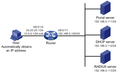
Configuration prerequisites and guidelines
· Configure IP addresses for the router and servers as shown in Figure 24 and make sure the host, router, and servers can reach each other.
· Configure the RADIUS server correctly to provide authentication and accounting functions.
· For re-DHCP portal authentication, configure a public address pool (20.20.20.0/24) and a private address pool (10.0.0.0/24) on the DHCP server. (Details not shown.)
· For re-DHCP portal authentication:
¡ The router must be configured as a DHCP relay agent.
¡ The portal-enabled interface must be configured with a primary IP address (a public IP address) and a secondary IP address (a private IP address).
For information about DHCP relay agent configuration, see Layer 3—IP Services Configuration Guide.
· Make sure the IP address of the portal device added on the portal server is the public IP address (20.20.20.1) of the router's interface connecting the host. The private IP address range for the IP address group associated with the portal device is the private subnet 10.0.0.0/24 where the host resides. The public IP address range for the IP address group is the public subnet 20.20.20.0/24.
· If you have configured a preauthentication IP address pool on portal-enabled interfaces, configure a DHCP relay address pool with the same name on the device. For the DHCP relay address pool, specify the subnet address where the unauthenticated users reside (with the export-router keyword specified) and the DHCP server address.
· To enable the router to redirect HTTPS packets, specify the HTTPS redirect listening port number on the router by using the http-redirect https-port command. For more information about this configuration, see HTTP redirect in Layer 3—IP Services Configuration Guide.
Procedure
Perform the following tasks on the router.
1. Configure a portal preauthentication policy:
# Create a portal preauthentication policy named abc.
<Router> system-view
[Router] portal pre-auth policy abc
# Specify user attribute ACL 3010 in the portal preauthentication policy.
[Router-pre-auth-abc] user-attribute acl 3010
[Router-pre-auth-abc] quit
# In ACL 3010, configure a rule to permit access to the subnet 192.168.0.0/24.
[Router] acl advanced 3010
[Router-acl-ipv4-adv-3010] rule 1 permit ip destination 192.168.0.0 0.0.0.255
[Router-acl-ipv4-adv-3010] quit
# Apply portal preauthentication policy abc to GigabitEthernet 3/1/2.
[Router] interface gigabitethernet 3/1/2
[Router–GigabitEthernet3/1/2] portal apply pre-auth-policy abc
[Router–GigabitEthernet3/1/2] quit
2. Configure DHCP relay and authorized ARP.
|
|
NOTE: For portal users to come online, do not enable recording client information in relay entries on the DHCP relay agent by using the dhcp relay client-information record command. |
# Configure DHCP relay.
[Router] dhcp enable
[Router] interface gigabitethernet 3/1/2
[Router–GigabitEthernet3/1/2] ip address 20.20.20.1 255.255.255.0
[Router–GigabitEthernet3/1/2] ip address 10.0.0.1 255.255.255.0 sub
[Router-GigabitEthernet3/1/2] dhcp select relay
[Router-GigabitEthernet3/1/2] dhcp relay server-address 192.168.0.112
# Enable authorized ARP.
[Router-GigabitEthernet3/1/2] arp authorized enable
[Router-GigabitEthernet3/1/2] quit
3. Configure portal authentication:
# Configure a portal authentication server.
[Router] portal server newpt
[Router-portal-server-newpt] ip 192.168.0.111 key simple portal
[Router-portal-server-newpt] port 50100
[Router-portal-server-newpt] quit
# Configure a portal Web server.
[Router] portal web-server newpt
[Router-portal-websvr-newpt] url http://192.168.0.111:8080/portal
[Router-portal-websvr-newpt] quit
# Specify the HTTPS redirect listening port number.
[Router] http-redirect https-port 8888
# Enable re-DHCP portal authentication on GigabitEthernet 3/1/2.
[Router] interface gigabitethernet 3/1/2
[Router–GigabitEthernet3/1/2] portal enable method redhcp
# Reference the portal Web server newpt on GigabitEthernet 3/1/2.
[Router–GigabitEthernet3/1/2] portal apply web-server newpt
# Configure the BAS-IP as 20.20.20.1 for portal packets sent from GigabitEthernet 3/1/2 to the portal authentication server.
[Router–GigabitEthernet3/1/2] portal bas-ip 20.20.20.1
[Router–GigabitEthernet3/1/2] quit
Verifying the configuration
# Verify the portal configuration by executing the display portal interface command. (Details not shown.)
# Display information about preauthentication portal users.
[Router] display portal user pre-auth interface gigabitethernet 3/1/2
MAC IP VLAN Interface
0015-e9a6-7cfe 10.10.10.4 -- GigabitEthernet3/1/2
State: Online
VPN instance: N/A
Authorization information:
User profile: N/A
Session group profile: N/A
ACL number: 3010 (active)
Inbound CAR: N/A
Outbound CAR: N/A
Inbound priority: N/A
Outbound priority: N/A
Example: Configuring direct portal authentication using a local portal Web service
Network configuration
As shown in Figure 25, the host is directly connected to the router (the access device). The host is assigned a public IP address either manually or through DHCP. The router acts as both a portal authentication server and a portal Web server. A RADIUS server acts as the authentication/accounting server.
Configure direct portal authentication on the router. Before a user passes portal authentication, the user can access only the portal Web server. After passing portal authentication, the user can access other network resources.
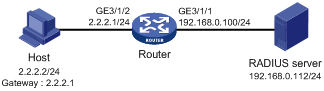
Configuration prerequisites and guidelines
· Configure IP addresses for the host, router, and server as shown in Figure 25 and make sure they can reach each other.
· Configure the RADIUS server correctly to provide authentication and accounting functions.
· Customize the authentication pages, compress them to a file, and upload the file to the root directory of the storage medium of the router.
Procedure
1. Configure a RADIUS scheme:
# Create a RADIUS scheme named rs1 and enter its view.
<Router> system-view
[Router] radius scheme rs1
# Specify the primary authentication server and primary accounting server, and configure the keys for communication with the servers.
[Router-radius-rs1] primary authentication 192.168.0.112
[Router-radius-rs1] primary accounting 192.168.0.112
[Router-radius-rs1] key authentication simple radius
[Router-radius-rs1] key accounting simple radius
# Exclude the ISP domain name from the username sent to the RADIUS server.
[Router-radius-rs1] user-name-format without-domain
[Router-radius-rs1] quit
# Enable RADIUS session control.
[Router] radius session-control enable
2. Configure an authentication domain:
# Create an ISP domain named dm1 and enter its view.
[Router] domain name dm1
# Configure AAA methods for the ISP domain.
[Router-isp-dm1] authentication portal radius-scheme rs1
[Router-isp-dm1] authorization portal radius-scheme rs1
[Router-isp-dm1] accounting portal radius-scheme rs1
[Router-isp-dm1] quit
# Configure domain dm1 as the default ISP domain. If a user enters the username without the ISP domain name at login, the authentication and accounting methods of the default domain are used for the user.
[Router] domain default enable dm1
3. Configure portal authentication:
# Create a portal Web server named newpt and specify http://2.2.2.1:2331/portal as the URL of the portal Web server. The IP address in the URL must be the IP address of a Layer 3 interface routable to the portal client or a loopback interface (except 127.0.0.1) on the device.
[Router] portal web-server newpt
[Router-portal-websvr-newpt] url http://2.2.2.1:2331/portal
[Router-portal-websvr-newpt] quit
# Enable direct portal authentication on GigabitEthernet 3/1/2.
[Router] interface gigabitethernet 3/1/2
[Router–GigabitEthernet3/1/2] portal enable method direct
# Specify portal Web server newpt on GigabitEthernet 3/1/2.
[Router–GigabitEthernet3/1/2] portal apply web-server newpt
[Router–GigabitEthernet3/1/2] quit
# Create an HTTP-based local portal Web service and enter its view.
[Router] portal local-web-server http
# Specify file abc.zip as the default authentication page file for the local portal Web service. (Make sure the file exist under the root directory of the router.)
[Router–portal-local-websvr-http] default-logon-page abc.zip
# Set the HTTP listening port number to 2331 for the local portal Web service.
[Router–portal-local-webserver-http] tcp-port 2331
[Router–portal-local-websvr-http] quit
Verifying the configuration
# Verify that the portal configuration has taken effect.
[Router] display portal interface gigabitethernet 3/1/2
Portal information of GigabitEthernet3/1/2
NAS-ID profile: Not configured
Authorization Strict checking
ACL Disabled
User profile Disabled
IPv4:
Portal status: Enabled
Portal authentication method: Direct
Portal web server: newpt
Portal mac-trigger-server: Not configured
Authentication domain: Not configured
Pre-auth policy: Not configured
User-dhcp-only: Disabled
Pre-auth IP pool: Not configured
Max Portal users: Not configured
Bas-ip: Not configured
User detection: Not configured
Action for server detection:
Server type Server name Action
-- -- --
Layer3 source network:
IP address Mask
IPv6:
Portal status: Disabled
Portal authentication method: Disabled
Portal web server: Not configured
Portal mac-trigger-server: Not configured
Authentication domain: Not configured
Pre-auth policy: Not configured
User-dhcp-only: Disabled
Pre-auth IP pool: Not configured
Max Portal users: Not configured
Bas-ipv6: Not configured
User detection: Not configured
Action for server detection:
Server type Server name Action
-- -- --
Layer3 source network:
IP address Prefix length
A user can perform portal authentication through a Web page. Before passing the authentication, the user can access only the authentication page http://2.2.2.1:2331/portal and all Web requests will be redirected to the authentication page. After passing the authentication, the user can access other network resources.
# After the user passes authentication, use the following command to display information about the portal user.
[Router] display portal user interface gigabitethernet 3/1/2
Total portal users: 1
Username: abc
Portal server: newpt
State: Online
VPN instance: N/A
MAC IP VLAN Interface
0015-e9a6-7cfe 2.2.2.2 -- GigabitEthernet3/1/2
Authorization information:
DHCP IP pool: N/A
User profile: N/A
Session group profile: N/A
ACL number: N/A
Inbound CAR: N/A
Outbound CAR: N/A
Inbound priority: N/A
Outbound priority: N/A
Example: Configuring MAC-based quick portal authentication
Network configuration
As shown in Figure 26, the host accesses the network through the router. The host is assigned a public IP address either manually or through DHCP. A portal server acts as a portal authentication server, a portal Web server, and a MAC binding server. A RADIUS server acts as the authentication/accounting server.
Configure direct portal authentication, so the host can access only the portal Web server before passing the authentication and can access other network resources after passing the authentication.
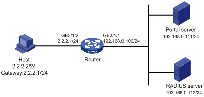
Restrictions and guidelines
To enable the router to redirect HTTPS packets, specify the HTTPS redirect listening port number on the router by using the http-redirect https-port command. For more information about this configuration, see HTTP redirect in Layer 3—IP Services Configuration Guide.
Prerequisites
· Configure IP addresses for the host, router, and servers as shown in Figure 26 and make sure they can reach each other.
· Configure the RADIUS server correctly to provide authentication and accounting functions.
Configuring the portal server
In this example, the portal server runs on IMC PLAT 7.1(E0303), IMC EIA 7.1(F0303), and IMC EIP 7.1(F0303).
1. Configure the portal authentication server:
a. Log in to IMC and click the User tab.
b. Select User Access Policy > Portal Service > Server from the navigation tree to open the portal server configuration page, as shown in Figure 27.
c. Configure the portal server parameters as needed.
This example uses the default values.
d. Click OK.
Figure 27 Portal authentication server configuration
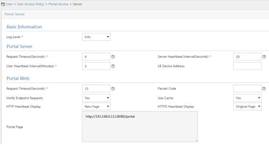
2. Configure the IP address group:
a. Select User Access Policy > Portal Service > IP Group from the navigation tree to open the portal IP address group configuration page.
b. Click Add to open the page as shown in Figure 28.
c. Enter the IP group name.
d. Enter the start IP address and end IP address of the IP group.
Make sure the client IP address (2.2.2.2) is in the IP group.
e. Select a service group.
This example uses the default group Ungrouped.
f. Select Normal from the Action list.
g. Click OK.
Figure 28 Adding an IP address group
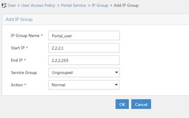
3. Add a portal device:
a. Select User Access Policy > Portal Service > Device from the navigation tree to open the portal device configuration page.
b. Click Add to open the page as shown in Figure 29.
c. Enter the device name.
d. Enter the IP address of the router's interface connected to the host.
e. Set whether to support the portal server heartbeat and user heartbeat functions.
In this example, select No for both Support Server Heartbeat and Support User Heartbeat.
f. Enter the key, which must be the same as that configured on the router.
g. Select Directly Connected for Access Method.
h. Click OK.
Figure 29 Adding a portal device
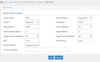
4. Associate the portal device with the IP address group:
a. As shown in Figure 30, click the Port Group Information Management icon for device NAS to open the port group configuration page.
b. Click Add to open the page as shown in Figure 31.
c. Enter the port group name.
d. Select the configured IP address group.
The IP address used by the user to access the network must be within this IP address group.
e. Select Supported for Transparent Authentication.
f. Use the default settings for other parameters.
g. Click OK.
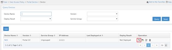
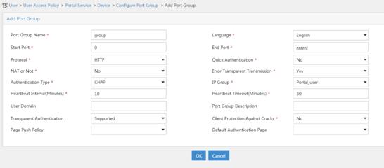
5. Select User Access Policy > Service Parameters > Validate System Configuration from the navigation tree to make the configurations take effect.
Configuring the MAC binding server
In this example, the MAC binding server runs on IMC PLAT 7.1(E0303), IMC EIA 7.1(F0303), and IMC EIP 7.1(F0303).
1. Add an access policy:
a. Select User Access Policy > Access Policy from the navigation tree to open the access policy page.
b. Click Add to open the page as shown in Figure 32.
c. Enter the access policy name.
d. Select a service group.
e. Use the default settings for other parameters.
f. Click OK.
Figure 32 Adding an access policy
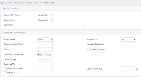
2. Add an access service:
a. Select User Access Policy > Access Service from the navigation tree to open the access service page.
b. Click Add to open the page as shown in Figure 33.
c. Enter the service name.
d. Select the Transparent Authentication on Portal Endpoints option.
e. Use the default settings for other parameters.
f. Click OK.
Figure 33 Adding an access service
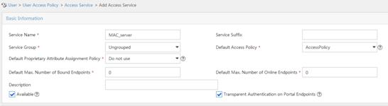
3. Add an access user:
a. Select Access User > All Access Users from the navigation tree to open the access user page.
b. Click Add to open the page as shown in Figure 34.
c. Select an access user.
d. Set the password.
e. Select a value from the Max. Transparent Portal Bindings list.
f. Click OK.
Figure 34 Adding an access user
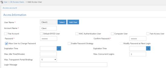
4. Configure system parameters:
a. Select User Access Policy > Service Parameters > System Settings from the navigation tree to open the system settings page.
b.
Click the Configure
icon ![]() for User Endpoint Settings to open
the page as shown in Figure 35.
for User Endpoint Settings to open
the page as shown in Figure 35.
c. Select whether to enable transparent portal authentication on non-smart devices.
In this example, select Enable for Non-Terminal Authentication.
d. Click OK.
e.
Click the Configure
icon ![]() for Endpoint Aging Time to open
the page as shown in Figure 36.
for Endpoint Aging Time to open
the page as shown in Figure 36.
f. Set the endpoint aging time as needed.
This example uses the default value.
Figure 35 Configuring user endpoint settings
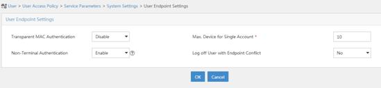
Figure 36 Setting the endpoint aging time
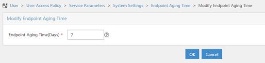
5. Select User Access Policy > Service Parameters > Validate System Configuration from the navigation tree to make the configurations take effect.
Configuring the router
1. Configure a RADIUS scheme:
# Create a RADIUS scheme named rs1 and enter its view.
<Router> system-view
[Router] radius scheme rs1
# Specify the primary authentication server and primary accounting server, and configure the keys for communication with the servers.
[Router-radius-rs1] primary authentication 192.168.0.112
[Router-radius-rs1] primary accounting 192.168.0.112
[Router-radius-rs1] key authentication simple radius
[Router-radius-rs1] key accounting simple radius
# Exclude the ISP domain name from the username sent to the RADIUS server.
[Router-radius-rs1] user-name-format without-domain
[Router-radius-rs1] quit
# Enable RADIUS session control.
[Router] radius session-control enable
2. Configure an authentication domain:
# Create an ISP domain named dm1 and enter its view.
[Router] domain name dm1
# Configure AAA methods for the ISP domain.
[Router-isp-dm1] authentication portal radius-scheme rs1
[Router-isp-dm1] authorization portal radius-scheme rs1
[Router-isp-dm1] accounting portal radius-scheme rs1
[Router-isp-dm1] quit
# Configure domain dm1 as the default ISP domain. If a user enters the username without the ISP domain name at login, the authentication and accounting methods of the default domain are used for the user.
[Router] domain default enable dm1
3. Configure portal authentication:
# Configure a portal authentication server.
[Router] portal server newpt
[Router-portal-server-newpt] ip 192.168.0.111 key simple portal
[Router-portal-server-newpt] port 50100
[Router-portal-server-newpt] quit
# Configure a portal Web server.
[Router] portal web-server newpt
[Router-portal-websvr-newpt] url http://192.168.0.111:8080/portal
[Router-portal-websvr-newpt] quit
# Specify the HTTPS redirect listening port number.
[Router] http-redirect https-port 8888
# Enable direct authentication on GigabitEthernet 3/1/2.
[Router] interface gigabitethernet 3/1/2
[Router-GigabitEthernet3/1/2] portal enable method direct
# Specify the portal Web server newpt on GigabitEthernet 3/1/2.
[Router-GigabitEthernet3/1/2] portal apply web-server newpt
# Configure the BAS-IP as 2.2.2.1 for portal packets sent from GigabitEthernet 3/1/2 to the portal authentication server.
[Router-GigabitEthernet3/1/2] portal bas-ip 2.2.2.1
[Router-GigabitEthernet3/1/2] quit
4. Configure MAC-based quick portal authentication:
# Create the MAC binding server mts.
[Router] portal mac-trigger-server mts
# Set the free-traffic threshold for portal users to 1024000 bytes.
[Router-portal-mac-trigger-server-mts] free-traffic threshold 1024000
# Specify the IP address of the MAC binding server as 192.168.0.111.
[Router-portal-mac-trigger-server-mts] ip 192.168.0.111
[Router-portal-mac-trigger-server-mts] quit
# Specify the MAC binding server mts on GigabitEthernet 3/1/2.
[Router] interface gigabitethernet 3/1/2
[Router-GigabitEthernet3/1/2] portal apply mac-trigger-server mts
[Router-GigabitEthernet3/1/2] quit
Verifying the configuration
# Display information about the MAC binding server.
[Router] display portal mac-trigger-server name mts
Portal mac trigger server name: mts
Version : 1.0
Server type : IMC
IP : 192.168.0.111
Port : 50100
VPN instance : Not configured
Aging time : 300 seconds
Free-traffic threshold : 1024000 bytes
NAS-Port-Type : Not configured
Binding retry times : 3
Binding retry interval : 1 seconds
Authentication timeout : 3 minutes
A user can perform portal authentication by using the H3C iNode client or through a Web browser. Before passing the authentication, the user can access only the authentication page http://192.168.0.111:8080/portal. All Web requests from the user will be redirected to the authentication page. After passing the authentication, the user can access other network resources.
For the first portal authentication, the user is required to enter the username and password. When the user goes offline and then accesses the network again, the user does not need to enter the authentication username and password.
# Display portal user information.
[Router] display portal user interface gigabitethernet 3/1/2
Total portal users: 1
Username: Client1
Portal server: newpt
State: Online
VPN instance: N/A
MAC IP VLAN Interface
0015-e9a6-7cfe 2.2.2.2 -- GigabitEthernet3/1/2
Authorization information:
DHCP IP pool: N/A
User profile: N/A
Session group profile: N/A
ACL number: N/A
Inbound CAR: N/A
Outbound CAR: N/A
Inbound priority: N/A
Outbound priority: N/A
Troubleshooting portal
No portal authentication page is pushed for users
Symptom
When a user is redirected to the IMC portal authentication server, no portal authentication page or error message is prompted for the user. The login page is blank.
Analysis
The key configured on the portal access device and that configured on the portal authentication server are inconsistent. As a result, packet verification fails, and the portal authentication server refuses to push the authentication page.
Solution
Use the display this command in portal authentication server view on the access device to check whether a key is configured for the portal authentication server.
· If no key is configured, configure the right key.
· If a key is configured, use the ip or ipv6 command in the portal authentication server view to correct the key, or correct the key configured for the access device on the portal authentication server.
Cannot log out portal users on the access device
Symptom
You cannot use the portal delete-user command on the access device to log out a portal user, but the portal user can log out by clicking the Disconnect button on the portal authentication client.
Analysis
When you execute the portal delete-user command on the access device to log out a user, the access device sends an unsolicited logout notification message to the portal authentication server. The destination port number in the logout notification is the listening port number of the portal authentication server configured on the access device. If this listening port number is not the actual listening port number configured on the server, the server cannot receive the notification. As a result, the server does not log out the user.
When a user uses the Disconnect button on the authentication client to log out, the portal authentication server sends an unsolicited logout request message to the access device. The access device uses the source port in the logout request as the destination port in the logout ACK message. As a result, the portal authentication server can definitely receive the logout ACK message and log out the user.
Solution
1. Use the display portal server command to display the listening port of the portal authentication server configured on the access device.
2. Use the portal server command in system view to change the listening port number to the actual listening port of the portal authentication server.
Cannot log out portal users on the RADIUS server
Symptom
The access device uses the H3C IMC server as the RADIUS server to perform identity authentication for portal users. You cannot log out the portal users on the RADIUS server.
Analysis
The H3C IMC server uses session control packets to send disconnection requests to the access device. On the access device, the listening UDP port for session control packets is disabled by default. Therefore, the access device cannot receive the portal user logout requests from the RADIUS server.
Solution
On the access device, execute the radius session-control enable command in system view to enable the RADIUS session control function.
Users logged out by the access device still exist on the portal authentication server
Symptom
After you log out a portal user on the access device, the user still exists on the portal authentication server.
Analysis
When you execute the portal delete-user command on the access device to log out a user, the access device sends an unsolicited logout notification to the portal authentication server. If the BAS-IP or BAS-IPv6 address carried in the logout notification is different from the portal device IP address specified on the portal authentication server, the portal authentication server discards the logout notification. When sending of the logout notifications times out, the access device logs out the user. However, the portal authentication server does not receive the logout notification successfully, and therefore it regards the user is still online.
Solution
Configure the BAS-IP or BAS-IPv6 attribute on the interface enabled with portal authentication. Make sure the attribute value is the same as the portal device IP address specified on the portal authentication server.
Re-DHCP portal authenticated users cannot log in successfully
Symptom
The device performs re-DHCP portal authentication for users. A user enters the correct username and password, and the client successfully obtains the private and public IP addresses. However, the authentication result for the user is failure.
Analysis
When the access device detects that the client IP address is changed, it sends an unsolicited portal packet to notify of the IP change to the portal authentication server. The portal authentication server notifies of the authentication success only after it receives the IP change notification from both the access device and the client.
If the BAS-IP or BAS-IPv6 address carried in the portal notification packet is different from the portal device IP address specified on the portal authentication server, the portal authentication server discards the portal notification packet. As a result, the portal authentication server considers that the user has failed the authentication.
Solution
Configure the BAS-IP or BAS-IPv6 attribute on the interface enabled with portal authentication. Make sure the attribute value is the same as the portal device IP address specified on the portal authentication server.