- Table of Contents
-
- H3C Access Controllers and Access Points Configuration Examples(V7)-6W101
- 00-Preface
- 01-H3C Access Controllers AP's Association with the AC at Layer 2 Configuration Examples
- 02-H3C Access Controllers Comware 7 AP's Association with the AC at Layer 2 (IPv6) Configuration Examples
- 03-H3C Access Controllers AP's Association with the AC at Layer 3 Configuration Examples
- 04-H3C Access Controllers Comware 7 AP's Association with the AC at Layer 3 (IPv6) Configuration Examples
- 05-H3C Access Controllers Local MAC Authentication Configuration Examples (V7)
- 06-H3C Access Controllers MAC Authentication with Guest VLAN Assignment Configuration Examples (V7)
- 07-H3C Access Controllers Comware 7 MAC Authentication with Guest VLAN Assignment (IPv6) Configuration Examples
- 08-H3C Access Controllers MAC Authentication and PSK Authentication Configuration Examples (V7)
- 09-H3C Access Controllers Auto AP Configuration Examples (V7)
- 10-H3C Access Controllers WLAN Load Balancing Configuration Examples (V7)
- 11-H3C Access Controllers WEP Encryption Configuration Examples
- 12-H3C Access Controllers Local Forwarding Configuration Examples
- 13-H3C Access Controllers Layer 2 Static Aggregation Configuration Examples (V7)
- 14-H3C Access Controllers Remote 802.1X Authentication Configuration Examples (V7)
- 15-H3C Access Controllers Comware 7 Remote 802.1X Authentication (IPv6) Configuration Examples
- 16-H3C Access Controllers 802.1X Authentication with ACL Assignment Through IMC Server @CE@ (V7)
- 17-H3C Access Controllers 802.1X Authentication with User Profile Assignment Through IMC Server @CE@ (V7)
- 18-H3C Access Controllers EAD Authentication Configuration Examples (V7)
- 19-H3C Access Controllers Comware 7 EAD Authentication (IPv6) Configuration Examples
- 20-H3C Access Controllers Remote Portal Authenticaiton Configuration Examples (V7)
- 21-H3C Access Controllers Comware 7 Remote Portal Authenticaiton (IPv6) Configuration Examples
- 22-H3C Access Controllers Local Portal Authentication Configuration Examples (V7)
- 23-H3C Access Controllers Comware 7 Local Portal Authentication (IPv6) Configuration Examples
- 24-H3C Access Controllers Local Forwarding Mode Direct Portal Authentication Configuration Examples (V7)
- 25-H3C Access Controllers Local Forwarding Mode Direct Portal Authentication (IPv6) Configuration Examples(V7)
- 26-H3C Access Controllers Local Portal Authentication through LDAP Server Configuration Examples (V7)
- 27-H3C Access Controllers Local Portal Authentication through LDAP Server (IPv6) Configuration Examples(V7)
- 28-H3C Access Controllers MAC-based Portal Quick Authenticaiton Configuration Example (V7)
- 29-H3C Access Controllers Comware 7 MAC-based Quick Portal Authenticaiton (IPv6) Configuration Example
- 30-H3C Access Controllers SSH Configuration Examples (7)
- 31-H3C Access Controllers Internal-to-External Access Through NAT Configuration Examples (V7)
- 32-H3C Access Controllers Static Blacklist Configuration Examples
- 33-H3C Access Controllers Comware 7 WLAN Access (IPv6) Configuration Examples
- 34-H3C Access Controllers Inter-AC Roaming Configuration Examples (V7)
- 35-H3C Access Controllers Comware 7 Inter-AC Roaming (IPv6) Configuration Examples
- 36-H3C Access Controllers HTTPS Login Configuration Examples (V7)
- 37-H3C Access Controllers Client Rate Limiting Configuration Examples (V7)
- 38-H3C Access Controllers Client Quantity Control Configuration Examples
- 39-H3C Access Controllers Medical RFID Tag Management Configuration Examples (V7)
- 40-H3C Access Controllers iBeacon Management Configuration Examples (V7)
- 41-H3C Access Controllers Remote AP Configuration Examples (V7)
- 42-H3C Access Controllers PSK Encryption Configuration Examples
- 43-H3C Access Controllers WIPS Configuration Examples (V7)
- 44-H3C Access Controllers Layer 2 Multicast Configuration Example (V7)
- 45-H3C Access Controllers IRF Setup with Members Directly Connected Configuration Examples (V7)
- 46-H3C Access Controllers IRF Setup with Members Not Directly Connected Configuration Examples (V7)
- 47-H3C Access Controller Modules IRF Setup with Members in One Chassis Configuration Examples (V7)
- 48-H3C Access Controller Modules IRF Setup with Members in Different Chassis Configuration Examples (V7)
- 49-H3C Access Controllers Comware 7 IP Source Guard (IPv6) Configuration Examples
- 50-Policy-Based Forwarding with Dual Gateways Configuration Example
- 51-H3C Access Controllers Comware 7 Policy-Based Forwarding with Dual Gateways (IPv6) Configuration Example
- 52-Policy-Based Local Forwarding Configuration Examples
- Related Documents
-
| Title | Size | Download |
|---|---|---|
| 33-H3C Access Controllers Comware 7 WLAN Access (IPv6) Configuration Examples | 72.18 KB |
|
|
|
H3C Access Controllers |
|
Comware 7 WLAN Access (IPv6) |
|
Configuration Examples |
Copyright © 2019 New H3C Technologies Co., Ltd. All rights reserved.
No part of this manual may be reproduced or transmitted in any form or by any means without prior written consent of New H3C Technologies Co., Ltd.
Except for the trademarks of New H3C Technologies Co., Ltd., any trademarks that may be mentioned in this document are the property of their respective owners.
The information in this document is subject to change without notice.
Introduction
The following information provides an IPv6 access configuration example.
Prerequisites
The following information applies to Comware 7-based access controllers and access points. Procedures and information in the examples might be slightly different depending on the software or hardware version of the access controllers and access points.
The configuration examples in this document were created and verified in a lab environment, and all the devices were started with the factory default configuration. When you are working on a live network, make sure you understand the potential impact of every command on your network.
This document assumes that you have basic knowledge of IPv6 basics and WLAN access.
Example: Configuring IPv6 WLAN access
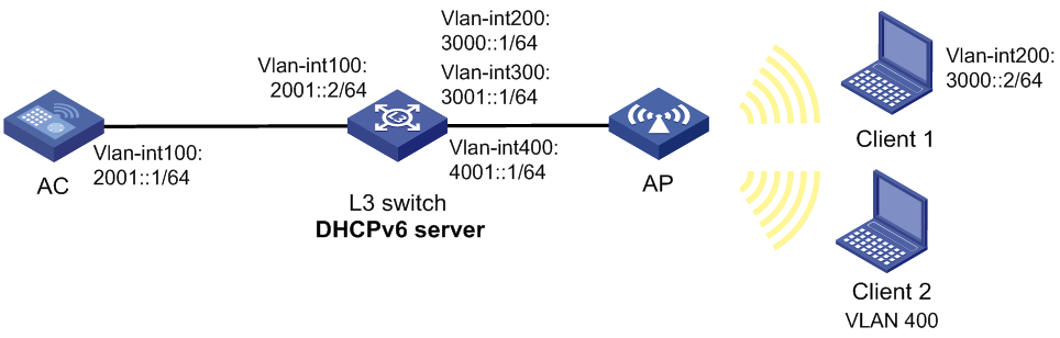
Network configuration
As shown in Figure 1, the Layer 3 switch acts as a DHCP server to assign IPv6 addresses to the AP and Client 1 and assign an IPv6 prefix to Client 2. Configure wireless services to ensure that the WLAN uses IPv6 addresses and Client 1 and Client 2 can access the WLAN. Assume that centralized forwarding is used in this example.
Restrictions and guidelines
When you configure IPv6 access, follow these restrictions and guidelines:
· Use the serial ID labeled on the AP's rear panel to specify an AP.
· To prevent too many packets from entering VLAN 1, configure the switch's interface that connects the switch to the AP to deny packets from VLAN 1.
Procedures
Configuring the AC
1. Configure the interfaces of the AC:
# Create VLAN 100 and VLAN-interface 100, and assign the interface an IPv6 address. The AC will use this IPv6 address to establish a CAPWAP tunnel with the AP.
<AC> system-view
[AC] vlan 100
[AC-vlan100] quit
[AC] interface vlan-interface 100
[AC-Vlan-interface100] ipv6 address 2001::1 64
[AC-Vlan-interface100] quit
# Create VLAN 200 and VLAN 400. The AC uses the VLANs to forward client traffic.
[AC] vlan 200
[AC-vlan200] quit
[AC] vlan 400
[AC-vlan400] quit
# Configure GigabitEthernet 1/0/1 that connects the AC to the switch as a trunk port, remove the port from VLAN 1, and assign the port to VLANs 100, 200, and 400.
[AC] interface gigabitethernet 1/0/1
[AC-GigabitEthernet1/0/1] port link-type trunk
[AC-GigabitEthernet1/0/1] undo port trunk permit vlan 1
[AC-GigabitEthernet1/0/1] port trunk permit vlan 100 200 400
[AC-GigabitEthernet1/0/1] quit
2. Configure IPv6 static routes.
[AC] ipv6 route-static 3001::0 64 2001::2
[AC] ipv6 route-static 4001::0 64 2001::2
3. Configure wireless services:
# Create service template 1 and enter its view.
[AC] wlan service-template 1
# Set the SSID to service1.
[AC-wlan-st-1] ssid service1
# Enable the service template.
[AC-wlan-st-1] service-template enable
# Enable snooping DHCPv6 and ND packets.
[AC-wlan-st-2] client ipv6-snooping dhcpv6-learning enable
[AC-wlan-st-2] client ipv6-snooping nd-learning enable
[AC-wlan-st-2] quit
# Create service template 2 and enter its view.
[AC] wlan service-template 2
# Set the SSID to service2.
[AC-wlan-st-2] ssid service2
# Enable the service template.
[AC-wlan-st-2] service-template enable
# Enable snooping DHCPv6 and ND packets.
[AC-wlan-st-2] client ipv6-snooping dhcpv6-learning enable
[AC-wlan-st-2] client ipv6-snooping nd-learning enable
[AC-wlan-st-2] quit
4. Configure the AP:
# Create manual AP officeap, and specify the AP model and serial ID.
[AC] wlan ap officeap model WA4320i-ACN
[AC-wlan-ap-officeap] serial-id 210235A1GQC158004457
# Bind service template 1 and VLAN 200 to radio 1.
[AC-wlan-ap-officeap] radio 1
[AC-wlan-ap-officeap-radio-1] service-template 1 vlan 200
# Enable radio 1.
[AC-wlan-ap-officeap-radio-1] radio enable
[AC-wlan-ap-officeap-radio-1] return
# Bind service template 2 and VLAN 400 to radio 2.
[AC-wlan-ap-officeap] radio 2
[AC-wlan-ap-officeap-radio-2] service-template 2 vlan 400
# Enable radio 2.
[AC-wlan-ap-officeap-radio-2] radio enable
[AC-wlan-ap-officeap-radio-2] return
Configuring the switch
1. Configure switch interfaces:
# Create VLAN 100, VLAN 300, VLAN-interface 100, and VLAN-interface 300, and assign IPv6 addresses to the VLAN interfaces. The switch will use VLAN 100 and VLAN 300 to forward packets between AC and AP.
<L3 switch> system-view
[L3 switch] vlan 100
[L3 switch-vlan100] quit
[L3 switch] interface vlan-interface 100
[L3 switch-Vlan-interface100] ipv6 address 2001::2/64
[L3 switch-Vlan-interface100] quit
[L3 switch] vlan 300
[L3 switch-vlan300] quit
[L3 switch] interface vlan-interface 300
[L3 switch-Vlan-interface300] ipv6 address 3001::1/64
[L3 switch-Vlan-interface300] quit
# Create VLAN 200 and VLAN-interface 200 and assign an IPv6 address to the VLAN interface. Client 1 will use this VLAN to access the WLAN.
[L3 switch] vlan 200
[L3 switch-vlan200] quit
[L3 switch] interface vlan-interface 200
[L3 switch-Vlan-interface200] ipv6 address 3000::1/64
[L3 switch-Vlan-interface200] quit
# Create VLAN 400 and VLAN-interface 400 and assign an IPv6 address to the VLAN interface. Client 2 will use this VLAN to access the WLAN.
[L3 switch] vlan 400
[L3 switch-vlan400] quit
[L3 switch] interface vlan-interface 400
[L3 switch-Vlan-interface400] ipv6 address 4000::1/64
[L3 switch-Vlan-interface400] quit
# Configure GigabitEthernet 1/0/1 that connects the switch to the AC as a trunk port, remove the port from VLAN 1, and assign the port to VLANs 100, 200, and 400.
[L3 Switch] interface gigabitethernet 1/0/1
[L3 Switch-GigabitEthernet1/0/1] port link-type trunk
[L3 switch-GigabitEthernet1/0/2] undo port trunk permit vlan 1
[L3 Switch-GigabitEthernet1/0/1] port trunk permit vlan 100 200 400
[L3 Switch-GigabitEthernet1/0/1] quit
# Configure GigabitEthernet 1/0/2 that connects the switch to the AP as a trunk port, remove the port from VLAN 1, configure the PVID as VLAN 300, and assign the port to VLANs 200, 300, and 400.
[L3 switch] interface gigabitEthernet 1/0/2
[L3 switch-GigabitEthernet1/0/2] port link-type trunk
[L3 switch-GigabitEthernet1/0/2] undo port trunk permit vlan 1
[L3 switch-GigabitEthernet1/0/2] port trunk permit vlan 200 300 400
[L3 switch-GigabitEthernet1/0/2] port trunk pvid vlan 300
[L3 switch-GigabitEthernet1/0/2] quit
2. Configure DHCPv6:
# Enable the DHCPv6 server on VLAN-interface 200, VLAN-interface 300, and VLAN-interface 400, respectively.
[L3 switch] interface vlan-interface 200
[L3 switch-Vlan-interface200] ipv6 dhcp select server
[L3 switch-Vlan-interface200] quit
[L3 switch] interface vlan-interface 300
[L3 switch-Vlan-interface300] ipv6 dhcp select server
[L3 switch-Vlan-interface300] quit
[L3 switch] interface vlan-interface 400
[L3 switch-Vlan-interface400] ipv6 dhcp select server
[L3 switch-Vlan-interface400] quit
# Disable RA message suppression, set both the managed address configuration flag (M) and the other stateful configuration flag (O) to 1 in RA advertisements to be sent for the created VLAN interfaces.
[L3 switch] interface vlan-interface 200
[L3 switch-Vlan-interface200] undo ipv6 nd ra halt
[L3 switch-Vlan-interface200] ipv6 nd autoconfig managed-address-flag
[L3 switch-Vlan-interface200] ipv6 nd autoconfig other-flag
[L3 switch-Vlan-interface200] quit
[L3 switch] interface vlan-interface 300
[L3 switch-Vlan-interface300] undo ipv6 nd ra halt
[L3 switch-Vlan-interface300] ipv6 nd autoconfig managed-address-flag
[L3 switch-Vlan-interface300] ipv6 nd autoconfig other-flag
[L3 switch-Vlan-interface300] quit
[L3 switch] interface vlan-interface 400
[L3 switch-Vlan-interface400] undo ipv6 nd ra halt
[L3 switch-Vlan-interface400] ipv6 nd autoconfig managed-address-flag
[L3 switch-Vlan-interface400] ipv6 nd autoconfig other-flag
[L3 switch-Vlan-interface400] quit
# Create DHCPv6 address pool 1 to assign an IPv6 address to Client 1, and specify subnet 3000::0/64 in the DHCP address pool.
[L3 switch] ipv6 dhcp pool 1
[L3 switch-dhcp6-pool-1] network 3000::0/64
[L3 switch-dhcp6-pool-1] gateway-list 3000::1
[L3 switch-dhcp6-pool-1] quit
# Create DHCPv6 address pool 2 to assign an IPv6 address to the AP, specify subnet 3001::0/64 in the DHCP address pool, and configure Option 52 that specifies AC IPv6 address 2001:1 in the address pool.
[L3 switch] ipv6 dhcp pool 2
[L3 switch-dhcp6-pool-2] network 3001::0/64
[L3 switch-dhcp6-pool-2] gateway-list 3001::1
[L3 switch-dhcp6-pool-2] option 52 hex 20010000000000000001000000000001
[L3 switch-dhcp6-pool-2] quit
# Create a prefix pool and specify the prefix and the assigned prefix length for the pool.
[L3 switch] ipv6 dhcp prefix-pool 1 prefix 4001::/64 assign-len 64
# Create DHCPv6 address pool 3 to assign an IPv6 address to Client 2, and specify subnet 4001::0/64 in the DHCP address pool.
[L3 switch] ipv6 dhcp pool 3
[L3 switch-dhcp6-pool-3] network 4001::0/64
[L3 switch-dhcp6-pool-3] gateway-list 4001::1
# Apply prefix pool 1 to DHCPv6 address pool 3, so the DHCPv6 server can dynamically select a prefix from the prefix pool for a client.
[L3 switch-dhcp6-pool-3] prefix-pool 1
[L3 switch-dhcp6-pool-3] quit
Verifying the configuration
# Verify that Client 1 and Client 2 have connected to the network successfully.
[AC] display wlan client
Total number of clients: 2
MAC address AP name RID IPv6 address VLAN
0000-000f-1211 officeap 1 3000::2 200
0000-000f-1212 officeap 2 4001::3 400
Configuration files
· AC:
#
vlan 100
#
vlan 200
#
vlan 400
#
interface Vlan-interface100
ipv6 address 2001::1/64
#
wlan service-template 1
ssid service
client ipv6-snooping dhcpv6-learning enable
client ipv6-snooping nd-learning enable
service-template enable
#
interface GigabitEthernet1/0/1
port link-type trunk
undo port trunk permit vlan 1
port trunk permit vlan 100 200 400
#
ipv6 route-static 3001::0 64 2001::2
ipv6 route-static 4001::0 64 2001::2
#
wlan ap officeap model WA4320i-ACN
serial-id 210235A1GQC158004457
radio 1
radio enable
service-template 1 vlan 200
radio 2
radio enable
service-template 2 vlan 400
#
· Layer 3 switch:
#
ipv6 dhcp prefix-pool 1 prefix 4001::/64 assign-len 64
# #
vlan 100
#
vlan 200
#
vlan 300
#
vlan 400
#
ipv6 dhcp pool 1
network 3000::0/64
gateway-list 3000::1
#
ipv6 dhcp pool 2
network 3001::0/64
gateway-list 3001::1
option 52 hex 00010000000000000001000000000001
#
#
ipv6 dhcp pool 3
network 4001::0/64
prefix-pool 1
gateway-list 4001::1
#
interface Vlan-interface100
ipv6 address 2001::2/64
#
interface Vlan-interface200
ipv6 dhcp select server
ipv6 address 3000::1/64
ipv6 nd autoconfig managed-address-flag
ipv6 nd autoconfig other-flag
undo ipv6 nd ra halt
#
interface Vlan-interface300
ipv6 dhcp select server
ipv6 address 3001::1/64
ipv6 nd autoconfig managed-address-flag
ipv6 nd autoconfig other-flag
undo ipv6 nd ra halt
#
interface Vlan-interface400
ipv6 dhcp select server
ipv6 address 4001::1/64
ipv6 nd autoconfig managed-address-flag
ipv6 nd autoconfig other-flag
undo ipv6 nd ra halt
#
interface GigabitEthernet1/0/1
port link-type trunk
undo port trunk permit vlan 1
port trunk permit vlan 100 200 400
#
interface GigabitEthernet1/0/2
port link-type trunk
undo port trunk permit vlan 1
port trunk permit vlan 200 300 400
port trunk pvid vlan 300
#
Related documentation
· Layer 3—IP Services Command Reference in H3C Access Controllers Command References
· Layer 3—IP Services Configuration Guide in H3C Access Controllers Configuration Guides
· WLAN Command Reference in H3C Access Controllers Command References
· WLAN Configuration Guide in H3C Access Controllers Configuration Guides