- Table of Contents
-
- H3C Access Controllers and Access Points Configuration Examples(V7)-6W101
- 00-Preface
- 01-H3C Access Controllers AP's Association with the AC at Layer 2 Configuration Examples
- 02-H3C Access Controllers Comware 7 AP's Association with the AC at Layer 2 (IPv6) Configuration Examples
- 03-H3C Access Controllers AP's Association with the AC at Layer 3 Configuration Examples
- 04-H3C Access Controllers Comware 7 AP's Association with the AC at Layer 3 (IPv6) Configuration Examples
- 05-H3C Access Controllers Local MAC Authentication Configuration Examples (V7)
- 06-H3C Access Controllers MAC Authentication with Guest VLAN Assignment Configuration Examples (V7)
- 07-H3C Access Controllers Comware 7 MAC Authentication with Guest VLAN Assignment (IPv6) Configuration Examples
- 08-H3C Access Controllers MAC Authentication and PSK Authentication Configuration Examples (V7)
- 09-H3C Access Controllers Auto AP Configuration Examples (V7)
- 10-H3C Access Controllers WLAN Load Balancing Configuration Examples (V7)
- 11-H3C Access Controllers WEP Encryption Configuration Examples
- 12-H3C Access Controllers Local Forwarding Configuration Examples
- 13-H3C Access Controllers Layer 2 Static Aggregation Configuration Examples (V7)
- 14-H3C Access Controllers Remote 802.1X Authentication Configuration Examples (V7)
- 15-H3C Access Controllers Comware 7 Remote 802.1X Authentication (IPv6) Configuration Examples
- 16-H3C Access Controllers 802.1X Authentication with ACL Assignment Through IMC Server @CE@ (V7)
- 17-H3C Access Controllers 802.1X Authentication with User Profile Assignment Through IMC Server @CE@ (V7)
- 18-H3C Access Controllers EAD Authentication Configuration Examples (V7)
- 19-H3C Access Controllers Comware 7 EAD Authentication (IPv6) Configuration Examples
- 20-H3C Access Controllers Remote Portal Authenticaiton Configuration Examples (V7)
- 21-H3C Access Controllers Comware 7 Remote Portal Authenticaiton (IPv6) Configuration Examples
- 22-H3C Access Controllers Local Portal Authentication Configuration Examples (V7)
- 23-H3C Access Controllers Comware 7 Local Portal Authentication (IPv6) Configuration Examples
- 24-H3C Access Controllers Local Forwarding Mode Direct Portal Authentication Configuration Examples (V7)
- 25-H3C Access Controllers Local Forwarding Mode Direct Portal Authentication (IPv6) Configuration Examples(V7)
- 26-H3C Access Controllers Local Portal Authentication through LDAP Server Configuration Examples (V7)
- 27-H3C Access Controllers Local Portal Authentication through LDAP Server (IPv6) Configuration Examples(V7)
- 28-H3C Access Controllers MAC-based Portal Quick Authenticaiton Configuration Example (V7)
- 29-H3C Access Controllers Comware 7 MAC-based Quick Portal Authenticaiton (IPv6) Configuration Example
- 30-H3C Access Controllers SSH Configuration Examples (7)
- 31-H3C Access Controllers Internal-to-External Access Through NAT Configuration Examples (V7)
- 32-H3C Access Controllers Static Blacklist Configuration Examples
- 33-H3C Access Controllers Comware 7 WLAN Access (IPv6) Configuration Examples
- 34-H3C Access Controllers Inter-AC Roaming Configuration Examples (V7)
- 35-H3C Access Controllers Comware 7 Inter-AC Roaming (IPv6) Configuration Examples
- 36-H3C Access Controllers HTTPS Login Configuration Examples (V7)
- 37-H3C Access Controllers Client Rate Limiting Configuration Examples (V7)
- 38-H3C Access Controllers Client Quantity Control Configuration Examples
- 39-H3C Access Controllers Medical RFID Tag Management Configuration Examples (V7)
- 40-H3C Access Controllers iBeacon Management Configuration Examples (V7)
- 41-H3C Access Controllers Remote AP Configuration Examples (V7)
- 42-H3C Access Controllers PSK Encryption Configuration Examples
- 43-H3C Access Controllers WIPS Configuration Examples (V7)
- 44-H3C Access Controllers Layer 2 Multicast Configuration Example (V7)
- 45-H3C Access Controllers IRF Setup with Members Directly Connected Configuration Examples (V7)
- 46-H3C Access Controllers IRF Setup with Members Not Directly Connected Configuration Examples (V7)
- 47-H3C Access Controller Modules IRF Setup with Members in One Chassis Configuration Examples (V7)
- 48-H3C Access Controller Modules IRF Setup with Members in Different Chassis Configuration Examples (V7)
- 49-H3C Access Controllers Comware 7 IP Source Guard (IPv6) Configuration Examples
- 50-Policy-Based Forwarding with Dual Gateways Configuration Example
- 51-H3C Access Controllers Comware 7 Policy-Based Forwarding with Dual Gateways (IPv6) Configuration Example
- 52-Policy-Based Local Forwarding Configuration Examples
- Related Documents
-
| Title | Size | Download |
|---|---|---|
| 14-H3C Access Controllers Remote 802.1X Authentication Configuration Examples (V7) | 155.41 KB |
|
|
|
H3C Access Controllers |
|
Comware 7 Remote 802.1X Authentication |
|
Configuration Examples |
Copyright © 2019 New H3C Technologies Co., Ltd. All rights reserved.
No part of this manual may be reproduced or transmitted in any form or by any means without prior written consent of New H3C Technologies Co., Ltd.
Except for the trademarks of New H3C Technologies Co., Ltd., any trademarks that may be mentioned in this document are the property of their respective owners.
The information in this document is subject to change without notice.
Introduction
This document provides an example for configuring remote 802.1X authentication for wireless clients.
Prerequisites
This document applies to Comware 7-based access controllers and access points. Procedures and information in the examples might be slightly different depending on the software or hardware version of the access controllers and access points.
The configuration examples in this document were created and verified in a lab environment, and all the devices were started with the factory default configuration. When you are working on a live network, make sure you understand the potential impact of every command on your network.
This document assumes that you have basic knowledge of WLAN access, WLAN security, WLAN authentication, and 802.1X.
Example: Configuring remote 802.1X authentication
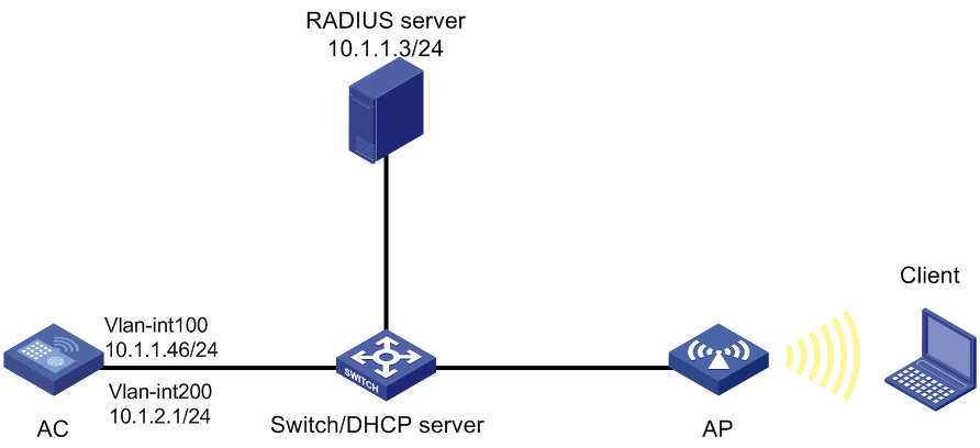
Network configuration
As shown in Figure 1, the switch acts as a DHCP server to assign IP addresses to the AP and the client. The RADIUS server runs on IMC.
Configure the AC, the client, the switch, and the RADIUS server to meet the following requirements:
· The AC uses the RADIUS server to perform 802.1X authentication for the wireless client.
· The AC uses the open system authentication for the client at the data link layer. This is the default authentication method.
· The AC uses the 802.1X AKM mode to secure data transmission between the client and the AP.
· The cipher suite is CCMP.
Restrictions and guidelines
When you configure remote 802.1X authentication for wireless clients, follow these restrictions and guidelines:
· Use the serial ID labeled on the AP's rear panel to specify an AP.
· For the IMC server to dynamically change the client authorization information or forcibly disconnect clients, enable the RADIUS session-control feature on the AC.
· To avoid dynamic authorization failures when the client is coming online, configure the RADIUS DAS feature.
Procedures
Configuring the AC
1. Configure interfaces on the AC:
# Create VLAN 100 and VLAN-interface 100, and assign an IP address to the VLAN interface. The AC will use this IP address to establish a CAPWAP tunnel with the AP.
<AC> system-view
[AC] vlan 100
[AC-vlan100] quit
[AC] interface vlan-interface 100
[AC-Vlan-interface100] ip address 10.1.1.46 24
[AC-Vlan-interface100] quit
# Create VLAN 200 and VLAN-interface 200, and assign an IP address to the VLAN interface. VLAN 200 will be used for client access.
[AC] vlan 200
[AC-vlan200] quit
[AC] interface vlan-interface 200
[AC-Vlan-interface200] ip address 10.1.2.1 24
[AC-Vlan-interface200] quit
2. Configure a RADIUS scheme:
# Create a RADIUS scheme named radius1 and enter its view.
[AC] radius scheme radius1
# Specify the IP addresses of the primary authentication and accounting RADIUS servers.
[AC-radius-radius1] primary authentication 10.1.1.3
[AC-radius-radius1] primary accounting 10.1.1.3
# Set the shared key to 12345 in plain text for secure communication with the servers.
[AC-radius-radius1] key authentication simple 12345
[AC-radius-radius1] key accounting simple 12345
# Specify IP address 10.1.2.1 as the source IP address for outgoing RADIUS packets.
[AC-radius-radius1] nas-ip 10.1.2.1
[AC-radius-radius1] quit
# Create an ISP domain named dom1 and enter its view.
[AC] domain dom1
# Apply RADIUS scheme radius1 to ISP domain dom1 for authentication, authorization, and accounting of LAN users.
[AC-isp-dom1] authentication lan-access radius-scheme radius1
[AC-isp-dom1] authorization lan-access radius-scheme radius1
[AC-isp-dom1] accounting lan-access radius-scheme radius1
[AC-isp-dom1] quit
# Enable the RADIUS session-control feature.
[AC] radius session-control enable
# Enable the RADIUS DAS feature and enter RADIUS DAS view.
[AC] radius dynamic-author server
# Specify the RADIUS server at 10.1.1.3 as a DAC and set the shared key to 12345 in plain text for validating DAE packets from the RADIUS server.
[AC-radius-da-server] client ip 10.1.1.3 key simple 12345
[AC-radius-da-server] quit
3. Configure the AC to use EAP relay to authenticate 802.1X clients.
[AC] dot1x authentication-method eap
4. Configure a wireless service:
# Create a service template named service and enter its view.
[AC] wlan service-template service
# Configure the SSID of the service template as service.
[AC-wlan-st-service] ssid service
# Assign clients coming online through the service template to VLAN 200.
[AC-wlan-st-service] vlan 200
# Set the AKM mode to 802.1X.
[AC-wlan-st-service] akm mode dot1x
# Set the cipher suite to CCMP.
[AC-wlan-st-service] cipher-suite ccmp
# Enable the RSN IE in beacon and probe responses.
[AC-wlan-st-service] security-ie rsn
# Set the authentication mode to 802.1X.
[AC-wlan-st-service] client-security authentication-mode dot1x
# Specify ISP domain dom1 for authenticating 802.1X clients.
[AC-wlan-st-service] dot1x domain dom1
# Enable the service template.
[AC-wlan-st-service] service-template enable
[AC-wlan-st-service] quit
5. Configure a manual AP:
# Create a manual AP named office, and specify the AP model and serial ID
[AC] wlan ap office model WA560-WW
[AC-wlan-ap-office] serial-id 219801A1NM8182032235
# Enter the view of radio 1.
[AC-wlan-ap-office] radio 1
# Bind service template service to radio 1, and enable radio1.
[AC-wlan-ap-office-radio-1] service-template service
[AC-wlan-ap-office-radio-1] radio enable
[AC-wlan-ap-office-radio-1] quit
[AC-wlan-ap-office] quit
Configuring the switch
# Create VLAN 100. The switch will use this VLAN to forward the traffic on the CAPWAP tunnel between the AC and AP.
<Switch> system-view
[Switch] vlan 100
[Switch-vlan100] quit
# Create VLAN 200. The switch will use this VLAN to forward packets for wireless clients.
[Switch] vlan 200
[Switch-vlan200] quit
# Configure GigabitEthernet 1/0/1 (port that connects the switch and the AC) as a trunk port, and assign the trunk port to VLANs 100 and 200.
[Switch] interface gigabitethernet 1/0/1
[Switch-GigabitEthernet1/0/1] port link-type trunk
[Switch-GigabitEthernet1/0/1] port trunk permit vlan 100 200
[Switch-GigabitEthernet1/0/1] quit
# Configure GigabitEthernet 1/0/2 (port that connects the switch and the AP) as an access port, and assign the port to VLAN 100.
[Switch] interface gigabitethernet 1/0/2
[Switch-GigabitEthernet1/0/2] port link-type access
[Switch-GigabitEthernet1/0/2] port access vlan 100
# Enable PoE on GigabitEthernet 1/0/2.
[Switch-GigabitEthernet1/0/2] poe enable
[Switch-GigabitEthernet1/0/2] quit
# Create VLAN-interface 100, and assign an IP address to the VLAN interface.
[Switch] interface vlan-interface 100
[Switch-Vlan-interface100] ip address 10.1.1.47 24
[Switch-Vlan-interface100] quit
# Create VLAN-interface 200, and assign an IP address to the VLAN interface.
[Switch] interface vlan-interface 200
[Switch-Vlan-interface200] ip address 10.1.2.2 24
[Switch-Vlan-interface200] quit
# Configure DHCP pool 100 to assign an IP address to the AP.
[Switch] dhcp server ip-pool 100
[Switch-dhcp-pool-100] network 10.1.1.0 mask 255.255.255.0
[Switch-dhcp-pool-100] gateway-list 10.1.1.46
[Switch-dhcp-pool-100] quit
# Configure DHCP pool 200 to assign an IP address to the client.
[Switch] dhcp server ip-pool 200
[Switch-dhcp-pool-200] network 10.1.2.0 mask 255.255.255.0
[Switch-dhcp-pool-200] gateway-list 10.1.2.1
[Switch-dhcp-pool-200] quit
# Enable DHCP.
[Switch] dhcp enable
Configuring the RADIUS server
In this example, the RADIUS server runs IMC PLAT 7.1(E0302) and IMC UAM 7.1(E0302).
1. Add the AC to IMC as an access device:
a. Log in to IMC and click the User tab.
b. From the navigation tree, select User Access Policy > Access Device Management > Access Device.
c. Click Add.
The Add Access Device page opens.
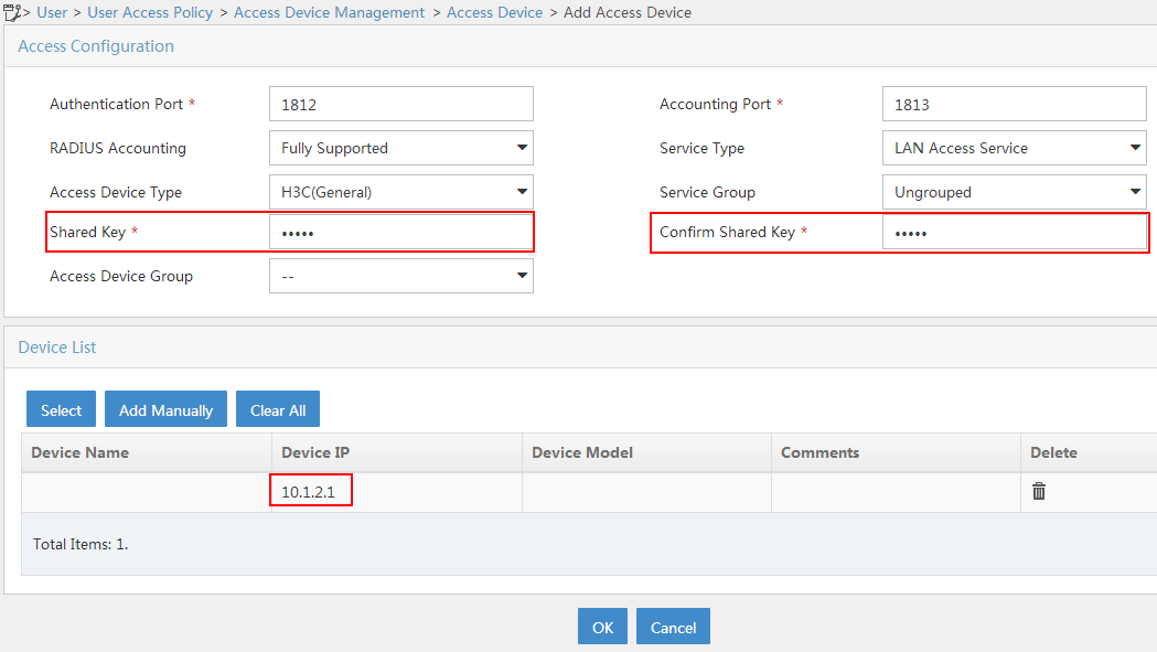
d. In the Access Configuration area, configure the following parameters, as shown in Figure 2:
- Enter 12345 in the Shared Key and Confirm Shared Key fields.
- Use the default values for other parameters.
e. In the Device List area, click Select or Add Manually to add the device at 10.1.2.1 as an access device.
f. Click OK.
Figure 2 Adding an access device
2. Add an access policy:
a. Click the User tab.
b. From the navigation tree, select User Access Policy > Access Policy.
c. Click Add.
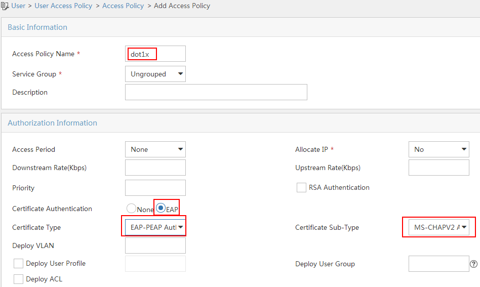
d. On the Add Access Policy page, configure the following parameters, as shown in Figure 3:
- Enter dot1x in the Access Policy Name field.
- Select EAP for the Certificate Authentication field.
- Select EAP-PEAP Auth from the Certificate Type list, and select MS-CHAPV2 Auth from the Certificate Sub-Type list.
The certificate sub-type on the IMC server must be the same as the identity authentication method configured on the client.
Figure 3 Adding an access policy
3. Add an access service:
a. Click the User tab.
b. From the navigation tree, select User Access Policy > Access Service.
c. Click Add.
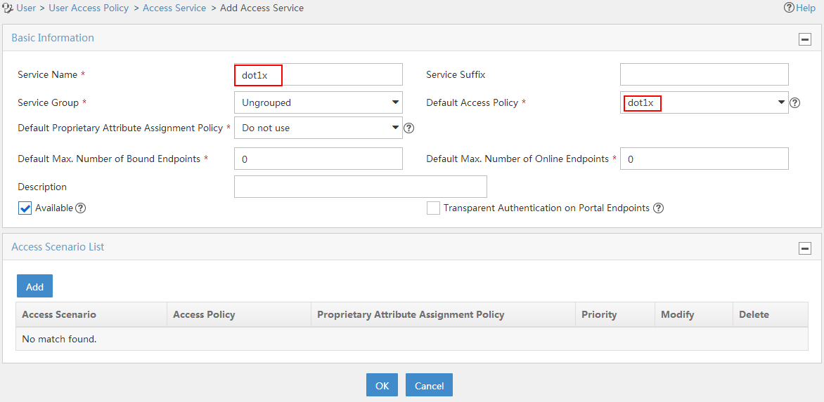
d. On the Add Access Service page, configure the following parameters, as shown in Figure 4:
- Enter dot1x in the Service Name field.
- Select dot1x from the Default Access Policy list.
e. Click OK.
Figure 4 Adding an access service
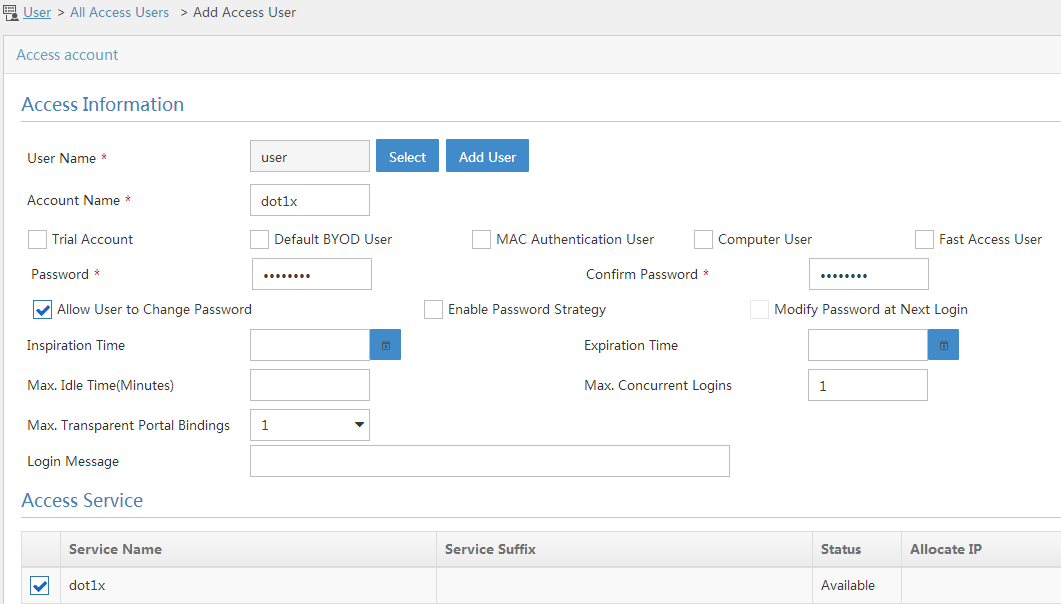
4. Add an access user:
a. Click the User tab.
b. From the navigation tree, select Access User > All Access Users.
The access user list opens.
c. Click Add.
The Add Access User page opens.
d. In the Access Information area, configure the following parameters, as shown in Figure 5:
- Click Select or Add User to associate the user with IMC Platform user user.
- Enter dot1x in the Account Name field.
- Enter dot1x123 in the Password and Confirm Password fields.
e. In the Access Service area, select dot1x from the list.
f. Click OK.
Figure 5 Adding an access user account
Configuring the WLAN client
Make sure the client has been installed with the EAP-PEAP certificate.
# Configure the wireless NIC, create wireless network service, and configure properties for the wireless network. (Details not shown.)
Verifying the configuration
1. On the client, verify that the client can pass authentication, associate with the AP, and access the wireless network. (Details not shown.)
2. On the AC, perform the following tasks to verify that the user has passed authentication and come online:
# Display detailed WLAN client information.
[AC] display wlan client verbose
Total number of clients: 1
MAC address : cc3a-61a8-fb8c
IPv4 address : 10.1.2.3
IPv6 address : N/A
Username : dot1x
AID : 1
AP ID : 3
AP name : office
Radio ID : 1
SSID : service
BSSID : 741f-4ad4-1fe0
VLAN ID : 200
Sleep count : 0
Wireless mode : 802.11ac
Channel bandwidth : 80MHz
SM power save : Disabled
Short GI for 20MHz : Supported
Short GI for 40MHz : Supported
Short GI for 80MHz : Supported
Short GI for 160/80+80MHz : Not supported
STBC RX capability : Not supported
STBC TX capability : Not supported
LDPC RX capability : Not supported
SU beamformee capability : Not supported
MU beamformee capability : Not supported
Beamformee STS capability : N/A
Block Ack : N/A
Supported VHT-MCS set : NSS1 0, 1, 2, 3, 4, 5, 6, 7, 8, 9
Supported HT MCS set : 0, 1, 2, 3, 4, 5, 6, 7
Supported rates : 6, 9, 12, 18, 24, 36, 48, 54 Mbps
QoS mode : WMM
Listen interval : 10
RSSI : 0
Rx/Tx rate : 0/0
Authentication method : Open system
Security mode : RSN
AKM mode : 802.1X
Cipher suite : CCMP
User authentication mode : 802.1X
Authorization ACL ID : N/A
Authorization user profile : N/A
Roam status : N/A
Key derivation : SHA1
PMF status : N/A
Forwarding policy name : N/A
Online time : 0days 0hours 0minutes 15seconds
FT status : Inactive
# Display online 802.1X client information.
[AC] display dot1x connection
Total connections: 1
User MAC address : cc3a-61a8-fb8c
AP name : office
Radio ID : 1
SSID : service
BSSID : 741f-4ad4-1fe0
Username : dot1x
Authentication domain : dom1
IPv4 address : 10.1.2.3
Authentication method : EAP
Initial VLAN : 200
Authorization VLAN : 200
Authorization ACL number : N/A
Authorization user profile : N/A
Termination action : Default
Session timeout period : 36000001 s
Online from : 2015/12/21 11:27:11
Online duration : 0h 1m 1s
Configuration files
· AC:
#
dot1x authentication-method eap
#
vlan 100
#
vlan 200
#
wlan service-template service
ssid service
vlan 200
akm mode dot1x
cipher-suite ccmp
security-ie rsn
client-security authentication-mode dot1x
dot1x domain dom1
service-template enable
#
interface Vlan-interface100
ip address 10.1.1.46 255.255.255.0
#
interface Vlan-interface200
ip address 10.1.2.1 255.255.255.0
#
radius scheme radius1
primary authentication 10.1.1.3
primary accounting 10.1.1.3
key authentication cipher $c$3$Bb61SHV2ZsVYPJU2+RFB/8ntk0uCQkmxdA==
key accounting cipher $c$3$w03NfxnBmfDuedv9/xo7ESnoxKjowmmX9A==
nas-ip 10.1.2.1
#
radius dynamic-author server
client ip 10.1.1.3 key cipher $c$3$AkTEB7OgMYnCqsfDeplhoAgXUek/rVrLZw==
#
radius session-control enable
#
domain dom1
authentication lan-access radius-scheme radius1
authorization lan-access radius-scheme radius1
accounting lan-access radius-scheme radius1
#
wlan ap office model WA560-WW
serial-id 219801A1NM8182032235
radio 1
radio enable
service-template service
#
· Switch:
#
dhcp enable
#
vlan 100
#
vlan 200
#
dhcp server ip-pool 100
network 10.1.1.0 mask 255.255.255.0
gateway-list 10.1.1.46
#
dhcp server ip-pool 200
network 10.1.2.0 mask 255.255.255.0
gateway-list 10.1.2.1
#
interface Vlan-interface100
ip address 10.1.1.47 255.255.255.0
#
interface Vlan-interface200
ip address 10.1.2.2 255.255.255.0
#
interface GigabitEthernet1/0/1
port link-type trunk
port trunk permit vlan 1 100 200
#
interface GigabitEthernet1/0/2
port access vlan 100
poe enable
#
Related documentation
· Security Command Reference in H3C Access Controllers Command References
· Security Configuration Guide in H3C Access Controllers Configuration Guides
· WLAN Command Reference in H3C Access Controllers Command References
· WLAN Configuration Guide in H3C Access Controllers Configuration Guides