- Table of Contents
-
- H3C S3100-52P Operation Manual-Release 1602(V1.01)
- 00-1Cover
- 00-2Product Overview
- 01-CLI Operation
- 02-Login Operation
- 03-Configuration File Management Operation
- 04-VLAN Operation
- 05-IP Address and Performance Operation
- 06-Voice VLAN Operation
- 07-GVRP Operation
- 08-Port Basic Configuration Operation
- 09-Link Aggregation Operation
- 10-Port Isolation Operation
- 11-Port Security-Port Binding Operation
- 12-DLDP Operation
- 13-MAC Address Table Management Operation
- 14-MSTP Operation
- 15-Static Route Operation
- 16-Multicast Operation
- 17-802.1x and System Guard Operation
- 18-AAA Operation
- 19-Web Authentication Operation
- 20-MAC Address Authentication Operation
- 21-ARP Operation
- 22-DHCP Operation
- 23-ACL Operation
- 24-QoS-QoS Profile Operation
- 25-Mirroring Operation
- 26-Stack-Cluster Operation
- 27-SNMP-RMON Operation
- 28-NTP Operation
- 29-SSH Operation
- 30-File System Management Operation
- 31-FTP-SFTP-TFTP Operation
- 32-Information Center Operation
- 33-System Maintenance and Debugging Operation
- 34-VLAN-VPN Operation
- 35-HWPing Operation
- 36-IPv6 Management Operation
- 37-DNS Operation
- 38-Smart Link-Monitor Link Operation
- 39-Appendix
- Related Documents
-
| Title | Size | Download |
|---|---|---|
| 31-FTP-SFTP-TFTP Operation | 189.16 KB |
Chapter 1 FTP and SFTP Configuration
1.1 Introduction to FTP and SFTP
1.2.1 FTP Configuration: A Switch Operating as an FTP Server
1.2.2 FTP Configuration: A Switch Operating as an FTP Client
1.2.3 Configuration Example: A Switch Operating as an FTP Server
1.2.4 FTP Banner Display Configuration Example
1.2.5 FTP Configuration: A Switch Operating as an FTP Client
1.3.1 SFTP Configuration: A Switch Operating as an SFTP Server
1.3.2 SFTP Configuration: A Switch Operating as an SFTP Client
1.3.3 SFTP Configuration Example
2.2.1 TFTP Configuration: A Switch Operating as a TFTP Client
2.2.2 TFTP Configuration Example
Chapter 1 FTP and SFTP Configuration
When configuring FTP and SFTP, go to these sections for information you are interested in:
l Introduction to FTP and SFTP
& Note:
FTP banner is newly added. For details, see section Configuring the banner for an FTP server.
1.1 Introduction to FTP and SFTP
1.1.1 Introduction to FTP
File Transfer Protocol (FTP) is commonly used in IP-based networks to transmit files. Before World Wide Web comes into being, files are transferred through command lines, and the most popular application is FTP. At present, although E-mail and Web are the usual methods for file transmission, FTP still has its strongholds.
As an application layer protocol, FTP is used for file transfer between remote server and local client. FTP uses TCP ports 20 and 21 for data transfer and control command transfer respectively. Basic FTP operations are described in RFC 959.
FTP-based file transmission is performed in the following two modes:
l Binary mode for program file transfer
l ASCII mode for text file transfer
An H3C S3100-52P Ethernet switch can act as an FTP client or the FTP server in FTP-employed data transmission:
Table 1-1 Roles that an H3C S3100-52P Ethernet switch acts as in FTP
|
Item |
Description |
Remarks |
|
FTP server |
An Ethernet switch can operate as an FTP server to provide file transmission services for FTP clients. You can log in to a switch operating as an FTP server by running an FTP client program on your PC to access files on the FTP server. |
The prerequisite is that a route exists between the switch and the PC. |
|
FTP client |
In this case, you need to establish a connection between your PC and the switch through a terminal emulation program or Telnet, execute the ftp X.X.X.X command on your PC. (X.X.X.X is the IP address of an FTP server or a host name), and enter your user name and password in turn. A switch can operate as an FTP client, through which you can access files on the FTP server. |
l With an S3100-52P Ethernet switch serving as an FTP server, the seven-segment digital LED on the front panel of the switch rotates clockwise when an FTP client is uploading files to the FTP server (the S3100-52P switch), and stops rotating when the file uploading is finished, as shown in Figure 1-1.
l With an S3100-52P Ethernet switch serving as an FTP client, the seven-segment digital LED on the front panel of the switch rotates clockwise when the FTP client (the S3100-52P switch) is downloading files from an FTP server, and stops rotating when the file downloading is finished, as shown in Figure 1-1.

Figure 1-1 Clockwise rotating of the seven-segment digital LED
1.1.2 Introduction to SFTP
Secure FTP (SFTP) is established based on an SSH2 connection. It allows a remote user to log in to a switch to manage and transmit files, providing a securer guarantee for data transmission. In addition, since the switch can be used as a client, you can log in to remote devices to transfer files securely.
1.2 FTP Configuration
Complete the following tasks to configure FTP:
|
Task |
Remarks |
|
|
Required |
||
|
Required |
||
|
Optional |
||
|
Specifying the source interface and source IP address for an FTP server |
Optional |
|
|
Optional |
||
|
Optional |
||
|
Optional |
||
|
— |
||
|
Specifying the source interface and source IP address for an FTP client |
Optional |
|
1.2.1 FTP Configuration: A Switch Operating as an FTP Server
I. Creating an FTP user
Follow these steps to create an FTP user:
|
To do… |
Use the command… |
Remarks |
|
Enter system view |
system-view |
— |
|
Add a local user and enter local user view |
local-user user-name |
Required By default, no local user is configured. |
|
Configure a password for the specified user |
password { simple | cipher } password |
Optional By default, no password is configured. |
|
Configure the service type as FTP |
service-type ftp |
Required By default, no service is configured. |
II. Enabling an FTP server
Follow these steps to enable an FTP server:
|
To do… |
Use the command… |
Remarks |
|
Enter system view |
system-view |
— |
|
Enable the FTP server function |
ftp server enable |
Required Disabled by default. |
& Note:
l Only one user can access an H3C S3100-52P Ethernet switch at a given time when the latter operates as an FTP server.
l Operating as an FTP server, an H3C S3100-52P Ethernet switch cannot receive a file whose size exceeds its storage space. The clients that attempt to upload such a file will be disconnected with the FTP server due to lack of storage space on the FTP server.
l You cannot access an H3C S3100-52P switch operating as an FTP server through Microsoft Internet Explorer. To do so, use other client software.
& Note:
To protect unused sockets against attacks, the S3100-52P Ethernet switch provides the following functions:
l TCP 21 is enabled only when you start the FTP server.
l TCP 21 is disabled when you shut down the FTP server.
III. Configuring connection idle time
After the idle time is configured, if the server does not receive service requests from a client within a specified time period, it terminates the connection with the client, thus preventing a user from occupying the connection for a long time without performing any operation.
Follow these steps to configure connection idle time:
|
To do… |
Use the command… |
Remarks |
|
Enter system view |
system-view |
— |
|
Configure the connection idle time for the FTP server |
ftp timeout minutes |
Optional 30 minutes by default |
IV. Specifying the source interface and source IP address for an FTP server
You can specify the source interface and source IP address for an FTP server to enhance server security. After this configuration, FTP clients can access this server only through the IP address of the specified interface or the specified IP address.
& Note:
Source interface refers to the existing VLAN interface or Loopback interface on the device. Source IP address refers to the IP address configured for the interface on the device. Each source interface corresponds to a source IP address. Therefore, specifying a source interface for the FTP server is the same as specifying the IP address of this interface as the source IP address.
Follow these steps to specify the source interface and source IP address for an FTP server:
|
To do… |
Use the command… |
Remarks |
|
Enter system view |
system-view |
— |
|
Specify the source interface for an FTP server |
ftp-server source-interface interface-type interface-number |
Use either command Not specified by default. |
|
Specifying the source IP address for an FTP server |
ftp-server source-ip ip-address |
& Note:
l The specified interface must be an existing one. Otherwise a prompt appears to show that the configuration fails.
l The value of the ip-address argument must be an IP address on the device where the configuration is performed. Otherwise a prompt appears to show that the configuration fails.
l You can specify only one source interface or source IP address for the FTP at one time. That is, only one of the commands ftp-server source-interface and ftp-server source-ip can be valid at one time. If you execute both of them, the new setting will overwrite the original one.
l If the switch (FTP server) is the command switch or member switch in a cluster, do not use the ftp-server source-ip command to specify the private IP address of the cluster as the source IP address of the FTP server. Otherwise, FTP does not take effect.
V. Disconnecting a specified user
On the FTP server, you can disconnect a specified user from the FTP server to secure the network.
Follow these steps to disconnect a specified user:
|
To do… |
Use the command… |
Remarks |
|
Enter system view |
system-view |
— |
|
On the FTP server, disconnect a specified user from the FTP server |
ftp disconnect user-name |
Required |
& Note:
With an H3C S3100-52P Ethernet switch acting as the FTP server, if a network administrator attempts to disconnect a user that is uploading/downloading data to/from the FTP server the S3100-52P Ethernet switch will disconnect the user after the data transmission is completed.
VI. Configuring the banner for an FTP server
Displaying a banner: With a banner configured on the FTP server, when you access the FTP server through FTP, the configured banner is displayed on the FTP client. Banner falls into the following two types:
l Login banner: After the connection between an FTP client and an FTP server is established, the FTP server outputs the configured login banner to the FTP client terminal.
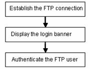
Figure 1-2 Process of displaying a login banner
l Shell banner: After the connection between an FTP client and an FTP server is established and correct user name and password are provided, the FTP server outputs the configured shell banner to the FTP client terminal.
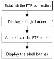
Figure 1-3 Process of displaying a shell banner
Follow these steps to configure the banner display for an FTP server:
|
To do… |
Use the command… |
Remarks |
|
Enter system view |
system-view |
— |
|
Configure a login banner |
header login text |
Required Use either command or both. By default, no banner is configured. |
|
Configure a shell banner |
header shell text |
& Note:
For details about the header command, refer to the Login part of the manual.
VII. Displaying FTP server information
|
To do… |
Use the command… |
Remarks |
|
Display the information about FTP server configurations on a switch |
display ftp-server |
Available in any view |
|
Display the source IP address set for an FTP server |
display ftp-server source-ip |
|
|
Display the login FTP client on an FTP server |
display ftp-user |
1.2.2 FTP Configuration: A Switch Operating as an FTP Client
I. Basic configurations on an FTP client
By default a switch can operate as an FTP client. In this case, you can connect the switch to the FTP server to perform FTP-related operations (such as creating/removing a directory) by executing commands on the switch.
Follow these steps to perform basic configurations on an FTP client:
|
To do… |
Use the command… |
Remarks |
|
Enter FTP client view |
ftp [ cluster | remote-server [ port-number ] ] |
— |
|
Specify to transfer files in ASCII characters |
ascii |
Use either command. By default, files are transferred in ASCII characters. |
|
Specify to transfer files in binary streams |
binary |
|
|
Set the data transfer mode to passive |
passive |
Optional passive by default. |
|
Change the working directory on the remote FTP server |
cd pathname |
Optional |
|
Change the working directory to be the parent directory |
cdup |
|
|
Get the local working path on the FTP client |
lcd |
|
|
Display the working directory on the FTP server |
pwd |
|
|
Create a directory on the remote FTP server |
mkdir pathname |
|
|
Remove a directory on the remote FTP server |
rmdir pathname |
|
|
Delete a specified file |
delete remotefile |
|
|
Query a specified file on the FTP server |
dir [ remotefile ] [ localfile ] |
Optional If no file name is specified, all the files in the current directory are displayed. The difference between these two commands is that the dir command can display the file name, directory as well as file attributes; while the Is command can display only the file name and directory. |
|
ls [ remotefile ] [ localfile ] |
||
|
Download a remote file from the FTP server |
get remotefile [ localfile ] |
Optional |
|
Upload a local file to the remote FTP server |
put localfile [ remotefile ] |
|
|
Rename a file on the remote server |
rename remote-source remote-dest |
|
|
Log in with the specified user name and password |
user username [ password ] |
|
|
Connect to a remote FTP server |
open { ip-address | server-name } [ port ] |
|
|
Terminate the current FTP connection without exiting FTP client view |
disconnect |
|
|
close |
||
|
Terminate the current FTP connection and return to user view |
quit |
|
|
bye |
||
|
Display the online help about a specified command concerning FTP |
remotehelp [ protocol-command ] |
|
|
Enable the verbose function |
verbose |
Optional Enabled by default. |
II. Specifying the source interface and source IP address for an FTP client
You can specify the source interface and source IP address for a switch acting as an FTP client, so that it can connect to a remote FTP server.
Follow these steps to specify the source interface and source IP address for an FTP client:
|
To do… |
Use the command… |
Remarks |
|
Specify the source interface used for the current connection |
ftp { cluster | remote-server } source-interface interface-type interface-number |
Optional |
|
Specify the source IP address used for the current connection |
ftp { cluster | remote-server } source-ip ip-address |
Optional |
|
Enter system view |
system-view |
— |
|
Specify an interface as the source interface the FTP client uses every time it connects to an FTP server |
ftp source-interface interface-type interface-number |
Use either command Not specified by default |
|
Specify an IP address as the source IP address the FTP client uses every time it connects to an FTP server |
ftp source-ip ip-address |
|
|
Display the source IP address used by an FTP client every time it connects to an FTP server |
display ftp source-ip |
Available in any view |
& Note:
l The specified interface must be an existing one. Otherwise a prompt appears to show that the configuration fails.
l The value of the ip-address argument must be the IP address of the device where the configuration is performed. Otherwise a prompt appears to show that the configuration fails.
l The source interface/source IP address set for one connection is prior to the fixed source interface/source IP address set for each connection. That is, for a connection between an FTP client and an FTP server, if you specify the source interface/source IP address used for the connection this time, and the specified source interface/source IP address is different from the fixed one, the former will be used for the connection this time.
l Only one fixed source interface or source IP address can be set for the FTP client at one time. That is, only one of the commands ftp source-interface and ftp source-ip can be valid at one time. If you execute both of them, the new setting will overwrite the original one.
1.2.3 Configuration Example: A Switch Operating as an FTP Server
I. Network requirements
A switch operates as an FTP server and a remote PC as an FTP client. The application switch.bin of the switch is stored on the PC. Upload the application to the remote switch through FTP and use the boot boot-loader command to specify switch.bin as the application for next startup. Reboot the switch to upgrade the switch application and download the configuration file config.cfg from the switch, thus to back up the configuration file.
l Create a user account on the FTP server with the username switch and password hello.
l The IP addresses 1.1.1.1 for a VLAN interface on the switch and 2.2.2.2 for the PC have been configured. Ensure that a route exists between the switch and the PC.
II. Network diagram

Figure 1-4 Network diagram for FTP configurations: a switch operating as an FTP server
III. Configuration procedure
1) Configure Switch A (the FTP server)
# Log in to the switch and enable the FTP server function on the switch. Configure the user name and password used to access FTP services, and specify the service type as FTP (You can log in to a switch through the Console port or by telnetting the switch. See the Login module for detailed information.)
# Configure the FTP username as switch, the password as hello, and the service type as FTP.
<Sysname>
<Sysname> system-view
[Sysname] ftp server enable
[Sysname] local-user switch
[Sysname-luser-switch] password simple hello
[Sysname-luser-switch] service-type ftp
2) Configure the PC (FTP client)
Run an FTP client application on the PC to connect to the FTP server. Upload the application named switch.bin to the root directory of the Flash memory of the FTP server, and download the configuration file named config.cfg from the FTP server. The following takes the command line window tool provided by Windows as an example:
# Enter the command line window and switch to the directory where the file switch.bin is located. In this example it is in the root directory of C:\.
C:\>
# Access the Ethernet switch through FTP. Input the username switch and password hello to log in and enter FTP view.
C:\> ftp 1.1.1.1
Connected to 1.1.1.1.
220 FTP service ready.
User (1.1.1.1:(none)): switch
331 Password required for switch.
Password:
230 User logged in.
ftp>
# Upload file switch.bin.
ftp> put switch.bin
200 Port command okay.
150 Opening ASCII mode data connection for switch.bin.
226 Transfer complete.
ftp: 75980 bytes received in 5.55 seconds 13.70Kbytes/sec.
# Download file config.cfg.
ftp> get config.cfg
200 Port command okay.
150 Opening ASCII mode data connection for config.cfg.
226 Transfer complete.
ftp: 3980 bytes received in 8.277 seconds 0.48Kbytes/sec.
This example uses the command line window tool provided by Windows. When you log in to the FTP server through another FTP client, refer to the corresponding instructions for operation description.
![]() Caution:
Caution:
l If available space on the Flash memory of the switch is not enough to hold the file to be uploaded, you need to delete files not in use from the Flash memory to make room for the file, and then upload the file again. The files in use cannot be deleted. If you have to delete the files in use to make room for the file to be uploaded, you can only delete/download them through the Boot ROM menu.
l H3C series switch is not shipped with FTP client application software. You need to purchase and install it by yourself.
3) Configure Switch A (FTP server)
# After uploading the application, use the boot boot-loader command to specify the uploaded file (switch.bin) to be the startup file used when the switch starts the next time, and restart the switch. Thus the switch application is upgraded.
<Sysname> boot boot-loader switch.bin
<Sysname> reboot
& Note:
For information about the boot boot-loader command and how to specify the startup file for a switch, refer to the System Maintenance and Debugging part of this manual.
1.2.4 FTP Banner Display Configuration Example
I. Network requirements
Configure the Ethernet switch as an FTP server and the remote PC as an FTP client. After a connection between the FTP client and the FTP server is established and login succeeds, the banner is displayed on the FTP client.
l An FTP user with username switch and the password hello has been configured on the FTP server.
l The IP addresses 1.1.1.1 for a VLAN interface on the switch and 2.2.2.2 for the PC have been configured. Ensure that a route exists between the switch and the PC.
l Configure the login banner of the switch as “login banner appears” and the shell banner as “shell banner appears”.
II. Network diagram
Figure 1-5 Network diagram for FTP banner display configuration
III. Configuration procedure
1) Configure the switch (FTP server)
# Configure the login banner of the switch as “login banner appears” and the shell banner as “shell banner appears”. For detailed configuration of other network requirements, see section Configuration Example: A Switch Operating as an FTP Server.
<Sysname> system-view
[Sysname] header login %login banner appears%
[Sysname] header shell %shell banner appears%
2) Configure the PC (FTP client)
# Access the Ethernet switch through FTP. Enter the username switch and the password hello to log in to the switch, and then enter FTP view. Login banner appears after FTP connection is established. Shell banner appears after the user passes the authentication.
C:\> ftp 1.1.1.1
Connected to 1.1.1.1.
220-login banner appears
220 FTP service ready.
User (1.1.1.1:(none)): switch
331 Password required for switch.
Password:
230-shell banner appears
230 User logged in.
ftp>
1.2.5 FTP Configuration: A Switch Operating as an FTP Client
I. Network requirements
A switch operates as an FTP client and a remote PC as an FTP server. The switch application named switch.bin is stored on the PC. Download it to the switch through FTP and use the boot boot-loader command to specify switch.bin as the application for next startup. Reboot the switch to upgrade the switch application, and then upload the switch configuration file named config.cfg to directory switch of the PC to back up the configuration file.
l Create a user account on the FTP server with the username switch and password hello, and grant the user switch read and write permissions for the directory switch on the PC.
l Configure the IP address 1.1.1.1 for a VLAN interface on the switch, and 2.2.2.2 for the PC. Ensure a route exists between the switch and the PC.
II. Network diagram

Figure 1-6 Network diagram for FTP configurations: a switch operating as an FTP client
III. Configuration procedure
1) Configure the PC (FTP server)
Perform FTP server–related configurations on the PC, that is, create a user account on the FTP server with username switch and password hello. (For detailed configuration, refer to the configuration instruction relevant to the FTP server software.)
2) Configure the switch (FTP client)
# Log in to the switch. (You can log in to a switch through the Console port or by telnetting the switch. See the Login module for detailed information.)
<Sysname>
![]() Caution:
Caution:
If available space on the Flash memory of the switch is not enough to hold the file to be uploaded, you need to delete files not in use from the Flash memory to make room for the file, and then upload the file again. The files in use cannot be deleted. If you have to delete the files in use to make room for the file to be uploaded, you can only delete/download them through the Boot ROM menu.
# Connect to the FTP server using the ftp command in user view. You need to provide the IP address of the FTP server, the user name and the password as well to enter FTP view.
<Sysname> ftp 2.2.2.2
Trying ...
Press CTRL+K to abort
Connected.
220 FTP service ready.
User(none):admin
331 Password required for admin.
Password:
230 User logged in.
[ftp]
# Enter the authorized directory on the FTP server.
[ftp] cd switch
# Execute the put command to upload the configuration file named config.cfg to the FTP server.
[ftp] put config.cfg
# Execute the get command to download the file named switch.bin to the Flash memory of the switch.
[ftp] get switch.bin
# Execute the quit command to terminate the FTP connection and return to user view.
[ftp] quit
<Sysname>
# After downloading the file, use the boot boot-loader command to specify the downloaded file (switch.bin) to be the application for next startup, and then restart the switch. Thus the switch application is upgraded.
<Sysname> boot boot-loader switch.bin
<Sysname> reboot
& Note:
For information about the boot boot-loader command and how to specify the startup file for a switch, refer to the System Maintenance and Debugging module of this manual.
1.3 SFTP Configuration
Complete the following tasks to configure SFTP:
|
Task |
Remarks |
|
|
Required |
||
|
Optional |
||
|
— |
||
|
— |
||
|
Specifying the source interface or source IP address for an SFTP client |
Optional |
|
1.3.1 SFTP Configuration: A Switch Operating as an SFTP Server
I. Enabling an SFTP server
Follow these steps to enable an SFTP server:
|
To do… |
Use the command… |
Remarks |
|
Enter system view |
system-view |
— |
|
Enable an SFTP server |
sftp server enable |
Required Disabled by default. |
II. Configuring connection idle time
Follow these steps to configure connection idle time:
|
To do… |
Use the command… |
Remarks |
|
Enter system view |
system-view |
— |
|
Configure the connection idle time for the SFTP server |
ftp timeout time-out-value |
Optional 10 minutes by default. |
III. Supported SFTP client software
An H3C S3100-52P Ethernet switch operating as an SFTP server can interoperate with SFTP client software, including SSH Tectia Client v4.2.0 (SFTP), v5.0, and WINSCP.
SFTP client software supports the following operations: logging in to a device; uploading a file; downloading a file; creating a directory; modify a file name or a directory name; browsing directory structure; and manually terminating a connection.
For configurations on client software, see the corresponding configuration manual.
& Note:
l Currently an H3C S3100-52P Ethernet switch operating as an SFTP server supports the connection of only one SFTP user. When multiple users attempt to log in to the SFTP server or multiple connections are enabled on a client, only the first user can log in to the SFTP user. The subsequent connection will fail.
l When you upload a large file through WINSCP, if a file with the same name exists on the server, you are recommended to set the packet timeout time to over 600 seconds, thus to prevent the client from failing to respond to device packets due to timeout. Similarly, when you delete a large file from the server, you are recommended to set the client packet timeout time to over 600 seconds.
1.3.2 SFTP Configuration: A Switch Operating as an SFTP Client
I. Basic configurations on an SFTP client
By default a switch can operate as an SFTP client. In this case you can connect the switch to the SFTP server to perform SFTP-related operations (such as creating/removing a directory) by executing commands on the switch.
Follow these steps to perform basic configurations on an SFTP client:
|
To do… |
Use the command… |
Remarks |
|
Enter system view |
system-view |
— |
|
Enter SFTP client view |
sftp { host-ip | host-name } [ port-num ] [ identity-key { dsa | rsa } | prefer_kex { dh_group1 | dh_exchange_group } | prefer_ctos_cipher { 3des | des | aes128 } | prefer_stoc_cipher { 3des | des | aes128 } | prefer_ctos_hmac { sha1 | sha1_96 | md5 | md5_96 } | prefer_stoc_hmac { sha1 | sha1_96 | md5 | md5_96 } ] * |
Required Support for the 3des keyword depends on the number of encryption bits of the software version. The 168-bit version supports this keyword, while the 56-bit version does not. |
|
Change the working directory on the remote SFTP server |
cd pathname |
Optional |
|
Change the working directory to be the parent directory |
cdup |
|
|
Display the working directory on the SFTP server |
pwd |
|
|
Create a directory on the remote SFTP server |
mkdir pathname |
|
|
Remove a directory on the remote SFTP server |
rmdir pathname |
|
|
Delete a specified file |
delete remotefile |
Optional Both commands have the same effect. |
|
remove remote-file |
||
|
Query a specified file on the SFTP server |
dir [ -a | -l ] [ remote-path ] |
Optional If no file name is provided, all the files in the current directory are displayed. The difference between these two commands is that the dir command can display the file name, directory as well as file attributes; while the Is command can display only the file name and directory. |
|
ls [ -a | -l ] [ remote-path ] |
||
|
Download a remote file from the SFTP server |
get remotefile [ localfile ] |
Optional |
|
Upload a local file to the remote SFTP server |
put localfile [ remotefile ] |
|
|
Rename a file on the remote server |
rename remote-source remote-dest |
|
|
Exit SFTP client view and return to system view |
bye |
The three commands have the same effect. |
|
exit |
||
|
quit |
||
|
Display the online help about a specified command concerning SFTP |
help [ all | command-name ] |
Optional |
& Note:
If you specify to authenticate a client through public key on the server, the client needs to read the local private key when logging in to the SFTP server. Since both RSA and DSA are available for public key authentication, you need to use the identity-key key word to specify the algorithms to get correct local private key; otherwise you will fail to log in. For details, see SSH Operation Manual.
II. Specifying the source interface or source IP address for an SFTP client
You can specify the source interface or source IP address for a switch acting as an FTP client, so that it can connect to a remote SFTP server.
Follow these steps to specify the source interface or source IP address for an SFTP client:
|
To do… |
Use the command… |
Remarks |
|
Enter system view |
system-view |
— |
|
Specify an interface as the source interface of the specified SFTP client |
sftp source-interface interface-type interface-number |
Use either command Not specified by default. |
|
Specify an IP address as the source IP address of the specified SFTP client |
sftp source-ip ip-address |
|
|
Display the source IP address used by the current SFTP client |
display sftp source-ip |
Optional Available in any view |
1.3.3 SFTP Configuration Example
I. Network requirements
As shown in Figure 1-7, establish an SSH connection between the SFTP client (switch A) and the SFTP server (switch B). Log in to switch B through switch A to manage and transmit files. An SFTP user with the username client001 and password abc exists on the SFTP server.
II. Network diagram

Figure 1-7 Network diagram for SFTP configuration
III. Configuration procedure
1) Configure the SFTP server (switch B)
# Create key pairs.
<Sysname> system-view
[Sysname] public-key local create rsa
[Sysname] public-key local create dsa
# Create a VLAN interface on the switch and assign to it an IP address, which is used as the destination address for the client to connect to the SFTP server.
[Sysname] interface vlan-interface 1
[Sysname-Vlan-interface1] ip address 192.168.0.1 255.255.255.0
[Sysname-Vlan-interface1] quit
# Specify the SSH authentication mode as AAA.
[Sysname] user-interface vty 0 4
[Sysname-ui-vty0-4] authentication-mode scheme
# Configure the protocol through which the remote user logs in to the switch as SSH.
[Sysname-ui-vty0-4] protocol inbound ssh
[Sysname-ui-vty0-4] quit
# Create a local user client001.
[Sysname] local-user client001
[Sysname-luser-client001] password simple abc
[Sysname-luser-client001] service-type ssh
[Sysname-luser-client001] quit
# Configure the authentication mode as password. Authentication timeout time, retry number, and update time of the server key adopt the default values.
[Sysname] ssh user client001 authentication-type password
# Specify the service type as SFTP.
[Sysname] ssh user client001 service-type sftp
# Enable the SFTP server.
[Sysname] sftp server enable
2) Configure the SFTP client (switch A)
# Configure the IP address of the VLAN interface on switch A. It must be in the same segment with the IP address of the VLAN interface on switch B. In this example, configure it as 192.168.0.2.
<Sysname> system-view
[Sysname] interface vlan-interface 1
[Sysname-Vlan-interface1] ip address 192.168.0.2 255.255.255.0
[Sysname-Vlan-interface1] quit
# Connect to the remote SFTP server. Enter the username client001 and the password abc, and then enter SFTP client view.
[Sysname] sftp 192.168.0.1
Input Username: client001
Trying 192.168.0.1 ...
Press CTRL+K to abort
Connected to 192.168.0.1 ...
The Server is not authenticated. Do you continue to access it?(Y/N):y
Do you want to save the server's public key?(Y/N):n
Enter password:
sftp-client>
# Display the current directory of the server. Delete the file z and verify the result.
sftp-client> dir
-rwxrwxrwx 1 noone nogroup 1759 Aug 23 06:52 config.cfg
-rwxrwxrwx 1 noone nogroup 225 Aug 24 08:01 pubkey2
-rwxrwxrwx 1 noone nogroup 283 Aug 24 07:39 pubkey1
drwxrwxrwx 1 noone nogroup 0 Sep 01 06:22 new
-rwxrwxrwx 1 noone nogroup 225 Sep 01 06:55 pub
-rwxrwxrwx 1 noone nogroup 0 Sep 01 08:00 z
Received status: End of file
Received status: Success
sftp-client> delete z
The following files will be deleted:
/z
Are you sure to delete it?(Y/N):y
This operation may take a long time.Please wait...
Received status: Success
File successfully Removed
sftp-client> dir
-rwxrwxrwx 1 noone nogroup 1759 Aug 23 06:52 config.cfg
-rwxrwxrwx 1 noone nogroup 225 Aug 24 08:01 pubkey2
-rwxrwxrwx 1 noone nogroup 283 Aug 24 07:39 pubkey1
drwxrwxrwx 1 noone nogroup 0 Sep 01 06:22 new
-rwxrwxrwx 1 noone nogroup 225 Sep 01 06:55 pub
Received status: End of file
Received status: Success
# Add a directory new1, and then check whether the new directory is successfully created.
sftp-client> mkdir new1
Received status: Success
New directory created
sftp-client> dir
-rwxrwxrwx 1 noone nogroup 1759 Aug 23 06:52 config.cfg
-rwxrwxrwx 1 noone nogroup 225 Aug 24 08:01 pubkey2
-rwxrwxrwx 1 noone nogroup 283 Aug 24 07:39 pubkey1
drwxrwxrwx 1 noone nogroup 0 Sep 01 06:22 new
-rwxrwxrwx 1 noone nogroup 225 Sep 01 06:55 pub
drwxrwxrwx 1 noone nogroup 0 Sep 02 06:30 new1
Received status: End of file
Received status: Success
# Rename the directory new1 as new2, and then verify the result.
sftp-client> rename new1 new2
File successfully renamed
sftp-client> dir
-rwxrwxrwx 1 noone nogroup 1759 Aug 23 06:52 config.cfg
-rwxrwxrwx 1 noone nogroup 225 Aug 24 08:01 pubkey2
-rwxrwxrwx 1 noone nogroup 283 Aug 24 07:39 pubkey1
drwxrwxrwx 1 noone nogroup 0 Sep 01 06:22 new
-rwxrwxrwx 1 noone nogroup 225 Sep 01 06:55 pub
drwxrwxrwx 1 noone nogroup 0 Sep 02 06:33 new2
Received status: End of file
Received status: Success
# Download the file pubkey2 from the server and rename it as public.
sftp-client> get pubkey2 public
This operation may take a long time, please wait...
.
Remote file:/pubkey2 ---> Local file: public..
Received status: End of file
Received status: Success
Downloading file successfully ended
# Upload file pu to the server and rename it as puk, and then verify the result.
sftp-client> put pu puk
This operation may take a long time, please wait...
Local file: pu ---> Remote file: /puk
Received status: Success
Uploading file successfully ended
sftp-client> dir
-rwxrwxrwx 1 noone nogroup 1759 Aug 23 06:52 config.cfg
-rwxrwxrwx 1 noone nogroup 225 Aug 24 08:01 pubkey2
-rwxrwxrwx 1 noone nogroup 283 Aug 24 07:39 pubkey1
drwxrwxrwx 1 noone nogroup 0 Sep 01 06:22 new
drwxrwxrwx 1 noone nogroup 0 Sep 02 06:33 new2
-rwxrwxrwx 1 noone nogroup 283 Sep 02 06:35 pub
-rwxrwxrwx 1 noone nogroup 283 Sep 02 06:36 puk
Received status: End of file
Received status: Success
sftp-client>
# Exit SFTP.
sftp-client> quit
Bye
[Sysname]
Chapter 2 TFTP Configuration
When configuring TFTP, go to these sections for information you are interested in:
2.1 Introduction to TFTP
Compared with FTP, Trivial File Transfer Protocol (TFTP) features simple interactive access interface and no authentication control. Therefore, TFTP is applicable in the networks where client-server interactions are relatively simple. TFTP is implemented based on UDP. It transfers data through UDP port 69. Basic TFTP operations are described in RFC 1986.
TFTP transmission is initiated by clients, as described in the following:
l To download a file, a client sends Read Request packets to the TFTP server, then receives data from the TFTP server, and sends acknowledgement packets to the TFTP server.
l To upload a file, a client sends Write Request packets to the TFTP server, then sends data to the TFTP server, and receives acknowledgement packets from the TFTP server.
An H3C S3100-52P Ethernet switch can act as a TFTP client only.
When an S3100-52P Ethernet switch serving as a TFTP client downloads files from the TFTP server, the seven-segment digital LED on the front panel of the switch rotates clockwise, and it stops rotating when the file downloading is finished, as shown in Figure 1-1.
When you download a file that is larger than the free space of the switch’s flash memory:
l If the TFTP server supports file size negotiation, file size negotiation will be initiated between the switch and the server and the file download operation will be aborted if the free space of the switch’s flash memory is found to be insufficient.
l If the TFTP server does not support file size negotiation, the switch will receive data from the server until the flash memory is full. If there is more data to be downloaded, the switch will prompt that the space is insufficient and delete the data partially downloaded. File download fails.
TFTP-based file transmission can be performed in the following modes:
l Binary mode for program file transfer.
l ASCII mode for text file transfer.
& Note:
Before performing TFTP-related configurations, you need to configure IP addresses for the TFTP client and the TFTP server, and make sure a route exists between the two.
2.2 TFTP Configuration
Complete the following tasks to configure TFTP:
|
Task |
Remarks |
|
|
— |
||
|
Specifying the source interface or source IP address for an FTP client |
Optional |
|
|
TFTP server configuration |
For details, see the corresponding manual |
— |
2.2.1 TFTP Configuration: A Switch Operating as a TFTP Client
I. Basic configurations on a TFTP client
By default a switch can operate as a TFTP client. In this case you can connect the switch to the TFTP server to perform TFTP-related operations (such as creating/removing a directory) by executing commands on the switch.
Follow these steps to perform basic configurations on a TFTP client:
|
To do… |
Use the command… |
Remarks |
|
Download a file from a TFTP server |
tftp tftp-server get source-file [ dest-file ] |
Optional |
|
Upload a file to a TFTP server |
tftp tftp-server put source-file [ dest-file ] |
Optional |
|
Enter system view |
system-view |
— |
|
Set the file transmission mode |
tftp { ascii | binary } |
Optional Binary by default. |
|
Specify an ACL rule used by the specified TFTP client to access a TFTP server |
tftp-server acl acl-number |
Optional Not specified by default. |
II. Specifying the source interface or source IP address for an FTP client
Follow these steps to specify the source interface and source IP address for a TFTP client:
|
To do… |
Use the command… |
Remarks |
|
Specify the source interface used for the current connection |
tftp tftp-server source-interface interface-type interface-number { get source-file [ dest-file ] | put source-file-url [ dest-file ] } |
Optional Not specified by default. |
|
Specify the source IP address used for the current connection |
tftp tftp-server source-ip ip-address { get source-file [ dest-file ] | put source-file-url [ dest-file ] } |
Optional Not specified by default. |
|
Enter system view |
system-view |
— |
|
Specify an interface as the source interface a TFTP client uses every time it connects to a TFTP server |
tftp source-interface interface-type interface-number |
Use either command Not specified by default. |
|
Specify an IP address as the source IP address a TFTP client uses every time it connects to a TFTP server |
tftp source-ip ip-address |
|
|
Display the source IP address used by a TFTP client every time it connects to a TFTP server |
display tftp source-ip |
Optional Available in any view |
& Note:
l The specified interface must be an existing one; otherwise a prompt appears to show that the configuration fails.
l The value of the ip-address argument must be an IP address on the device where the configuration is performed, and otherwise a prompt appears to show that the configuration fails.
l The source interface/source IP address set for one connection is prior to the fixed source interface/source IP address set for each connection. That is, for a connection between a TFTP client and a TFTP server, if you specify the source interface/source IP address only used for the connection this time, and the specified source interface/source IP address is different from the fixed one, the former will be used for the connection this time.
l You may specify only one source interface or source IP address for the TFTP client at one time. That is, only one of the commands tftp source-interface and tftp source-ip can be effective at one time. If both commands are configured, the one configured later will overwrite the original one.
2.2.2 TFTP Configuration Example
I. Network requirements
A switch operates as a TFTP client and a PC as the TFTP server. The application named switch.bin is stored on the PC. Download it (switch.bin) to the switch through TFTP, and use the boot boot-loader command to specify switch.bin as the application for next startup. Reboot the switch to upload the configuration file named config.cfg to the work directory on the PC to back up the configuration file.
l The TFTP working directory is configured on the TFTP server.
l Configure the IP addresses of a VLAN interface on the switch and the PC as 1.1.1.1 and 2.2.2.2 respectively. The port through which the switch connects with the PC belongs to the VLAN.
II. Network diagram

Figure 2-1 Network diagram for TFTP configurations
III. Configuration procedure
1) Configure the TFTP server (PC)
Start the TFTP server and configure the working directory on the PC.
2) Configure the TFTP client (switch).
# Log in to the switch. (You can log in to a switch through the Console port or by telnetting the switch. See the Login module for detailed information.)
<Sysname>
![]() Caution:
Caution:
If available space on the Flash memory of the switch is not enough to hold the file to be uploaded, you need to delete files not in use from the Flash memory to make room for the file, and then upload the file again. The files in use cannot be deleted. If you have to delete the files in use to make room for the file to be uploaded, you can only delete/download them through the Boot ROM menu.
# Enter system view
<Sysname> system-view
[Sysname]
# Configure the IP address of a VLAN interface on the switch to be 1.1.1.1, and ensure that the port through which the switch connects with the PC belongs to this VLAN. (This example assumes that the port belongs to VLAN 1.)
[Sysname] interface Vlan-interface 1
[Sysname-Vlan-interface1] ip address 1.1.1.1 255.255.255.0
[Sysname-Vlan-interface1] quit
# Download the switch application named switch.bin from the TFTP server to the switch.
<Sysname> tftp 2.2.2.2 get switch.bin switch.bin
# Upload the switch configuration file named config.cfg to the TFTP server.
<Sysname> tftp 2.2.2.2 put config.cfg config.cfg
# After downloading the file, use the boot boot-loader command to specify the downloaded file (switch.bin) to be the startup file used when the switch starts the next time, and restart the switch. Thus the switch application is upgraded.
<Sysname> boot boot-loader switch.bin
<Sysname> reboot
& Note:
For information about the boot boot-loader command and how to specify the startup file for a switch, refer to the System Maintenance and Debugging module of this manual.