- Table of Contents
-
- H3C S7500 Series Ethernet Switches Installation Manual-(V1.02)
- 00-1Cover
- 01-Chapter 1 Product Overview
- 02-Chapter 2 Line Processing Units
- 03-Chapter 3 Installation Preparations
- 04-Chapter 4 Hardware Installation
- 05-Chapter 5 System Commissioning
- 06-Chapter 6 Hardware Maintenance
- 07-Chapter 7 Software Maintenance
- 08-Chapter 8 Troubleshooting
- 09-Appendix A B68-22 Cabinet Installation
- 10-Appendix B N68 Cabinet Installation
- 11-Appendix C Lightning Protection
- 12-Appendix D AC Power Cables Used in Different Countries or Regions
- Related Documents
-
| Title | Size | Download |
|---|---|---|
| 10-Appendix B N68 Cabinet Installation | 1.88 MB |
Appendix B N68 Cabinet Installation
B.1.2 Requirements for Space Planning
B.1.3 Installation Preparation
B.2 Installing Cabinets on Cement Floor
B.2.1 Installing Cabinets with Feet
B.2.2 Installing Cabinets without Feet
B.3 Installing Cabinets on Antistatic Floor
B.3.1 Introduction to Supports and Guide rails
B.3.5 Installing Antistatic Floor Accessories
B.4 Installing Cabinet Accessories
B.4.3 Installing Protection Ground Cables
B.5 Introduction to Cabinet Cable Management
B.5.1 Introduction to Cabinet Grounding Points
B.5.2 Introduction to Cabinet Power Distribution
B.5.3 Introduction to Internal Cable Management
B.6.1 Remodeling an S7500 N68-18 Cabinet
B.6.2 Remodeling an S7500 N68-22 Cabinet
Appendix B N68 Cabinet Installation
B.1 Installing N68 Cabinets
B.1.1 Installation Overview
& Note:
l Two types of N68 cabinets are available. One is 1.8 meters high, with a headroom of 37 U; and the other is 2.2 meters high, with a headroom of 46 U. The installation requirements for both types of cabinets are the same, such as space planning, positioning and fixing cabinets.
l The following sections describe how to install a 2.2-meter-high N68 (N68-22) cabinet in details.
The dimensions of an N68-22 cabinet are 2200 × 600 × 800 mm (86.6 × 23.6 × 31.5 in.) (H × W × D), as shown in Figure B-1.
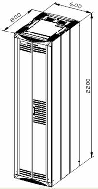
Figure B-1 Dimensions of the N68-22 cabinet
B.1.2 Requirements for Space Planning
Before installing the cabinet, you need to plan installation space first. Sufficient space must be provided in front of and at the back of the cabinet for maintenance. Figure B-2 describes the planning of installation space for a single cabinet. Figure B-3 describes the planning of side-by-side cabinet installation.

|
(2) Cabinet back |
(3) Cabinet outline |
Figure B-2 Planning of installation space for a single cabinet (in mm)

|
(2) Cabinet back |
(3) Cabinet outline |
Figure B-3 Planning of side-by-side cabinet installation (in mm)
B.1.3 Installation Preparation
Follow the given steps to do the installation preparation:
1) Draw lines correctly to avoid rework.
2) Unpack the cabinet and the cabinet accessories according to the operation guide.
![]() Caution:
Caution:
l If you need to install feet for the cabinet on cement floor, refer to Installing Cabinet Accessories”. Then proceed with step 3.
l After installing feet, you must fix the cabinets to avoid accidents.
l You can use supports to install cabinets on antistatic floor. You do not need to install feet.
& Note:
The way of fixing the cabinet with feet is not recommended.
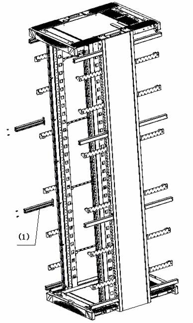
3) Put the rack in the upright position, and then remove wood boards and support wood bars from the back with a cross-head screwdriver. Put the removed boards and bars in a safe place to avoid injury. Keep the removed screws for later use.
|
(1) Support bar |
Figure B-4 Remove support bars
B.1.4 Installation Procedure
& Note:
The weight of an empty N68-22 cabinet is 160 kg (352.7 lb.) and that of an empty N68-18 cabinet is 120 kg (264.6 lb.). Before installing the cabinets, you must check load-bearing capacity of the floor as required.
Based on the floor types, the N68-22 cabinet can be installed on the cement floor or anti-static floor.
Figure B-5 describes the installation flow of the N68-22 cabinet.

Figure B-5 Installation flow of the N68-22 cabinet
& Note:
l If the cabinet is installed on the cement floor, after fixing the cabinet, you can install the cabinet accessories directly.
l If the cabinet is installed on the anti-static floor, after fixing the cabinet, you need to install anti-static floor holders and recover the floor, and then install the cabinet accessories.
B.2 Installing Cabinets on Cement Floor
This section describes how to install N68-22 cabinets on cement floor.
The dimensions of an N68-22 cabinet are 2200 x 600 x 800 mm (86.6 x 23.6 x 31.5 in.) (H × W × D). The internal headroom is 46 U. You can install cabinets with or without feet based on your requirements.
![]() Caution:
Caution:
You must install insulation components correctly to avoid connectivity with the ground before the ground cables are connected, thus satisfying insulation requirements.
B.2.1 Installing Cabinets with Feet
When installing cabinets with feet on cement floor, you need to use anchor plate components to fix the cabinets. Considering that the floor is not flat, the height of the feet is adjustable.
![]() Caution:
Caution:
Feet provide insulation and there are insulators in anchor plate components. These insulation components should be installed correctly so that the equipment is insulated from the ground before grounding cables are connected, thus meeting the insulation requirements.
l Anchor plate components
Anchor plate components of an N68 cabinet consist of an anchor plate and an expansion bolt. Figure B-6 illustrates the anchor plate components.

|
(1) Bolt M12×70 |
(2) Spring washer 12 |
(3) Big flat washer 12 |
(4) Insulation washer |
|
(5) Anchor plate |
(6) Insulation pad of the anchor plate |
||
|
(7) Expansion tube |
(8) Expansion bolt |
||
|
(9) Foot connection notch |
(10) Connection hole |
||
Figure B-6 Anchor plate components
l Foot components

|
(1) Fastening nut for cabinets |
(2) Fastening nut for anchor plate |
||
|
(3) Leveling nut |
|
(4) Foot |
|
l Installation procedure
Figure B-8 illustrates the procedure for installing N68-22 cabinets on cement floor.

Figure B-8 Install cabinets with feet on cement floor
I. Positioning the cabinets
1) Determine where to install the cabinets.
Before installing the cabinets, you need to plan installation space first. Sufficient space must be provided in front of and at the back of the cabinet for maintenance.
2) Make marks.
You can make marks in two ways: determining installation hole positions based on layout and determining installation hole positions based on the template.
Table B-1 Determine installation hole positions based on the layout
|
Step |
Operation |
Remarks |
|
1 |
Determine the installation positions of the expansion bolts according to the dimensions specified in the construction plan and the installation hole dimensions. |
Figure B-9 shows installation positions of the expansion bolts and feet for a single cabinet. Figure B-10 shows installation positions of the expansion bolts and feet used to combine a row of cabinets. |
|
2 |
Mark several points for drawing with a steel tape, and then draw two straight lines parallel to the benchmarks, with a spacing of 687 mm (27.0 in.). |
— |
|
3 |
Determine the hole positions of the expansion bolts for the first cabinet and foot positions on the two lines as designed. |
— |
|
4 |
With these holes as reference, mark the installation hole positions of the expansion bolts for other cabinets and foot positions. |
— |
|
5 |
Measure and confirm hole sizes again. |
— |

|
(1) Hole for fixing an expansion bolt |
(2) Mark for positioning feet |
|
|
(3) Cabinet outline |
|
(4) Inner wall or reference body |
Figure B-9 Installation positions of the expansion bolts and feet for a single cabinet
|
(1) Hole for fixing an expansion bolt |
(2) Mark for positioning feet |
|
(3) Cabinet outline |
(4) Inner wall or reference body |
Figure B-10 Installation positions of the expansion bolts and feet used to combine a row of cabinets
Table B-2 Determine installation hole positions based on the template
|
Step |
Operation |
Remarks |
|
1 |
Put the marking template on the floor as required. |
Figure B-11 shows the marking template. |
|
2 |
Mark the positions of all the expansion bolts and the feet on the floor according to the template. The semi-circle notch of the template indicates the front of the cabinet. |
Each cabinet needs four expansion bolt holes. |
![]() Caution:
Caution:
Make sure that the template direction is correct.

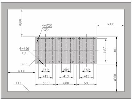
Figure B-11 Marking template (only for installation on cement floor)
3) Drill holes.
Use M12 expansion bolts to fix supports on the ground. Use a percussion drill with Ф16 bit to drill holes.
When drilling holes, hold the drill handle firmly with both hands, keeping the bit perpendicular to the floor to prevent damages to the floor or tilted holes.
The depth of the holes should range from 52 mm to 60 mm (2.0 in. to 2.4 in.). All the holes should have the same depth. After drilling a hole, use a dust collector to clean the dust inside and outside the holes before measuring the hole depth.
The bit is difficult to position on the floor that is hard and smooth. In this case, punch a small hole on the marks for the installation holes before drilling.
Note that the precision of marking and drilling is essential to hardware installation. Low precision can cause many problems during installation.
![]() Caution:
Caution:
The depth of drilling is between 52 mm and 60 mm (2.0 in. to 2.4 in.). Otherwise, you will be unable to install or fasten the expansion bolts.
4) Install expansion bolts.
Prior to installation, clean dust inside and outside the holes with a dust collector and then measure the spacing of holes. If errors are not acceptable, you must position and drill the holes again.
Take down the expansion tube and expansion
nut, and insert the alignment rib on the expansion nut into the alignment
groove of expansion tube. Punch the expansion tube with rubber hammer until the
expansion tube is completely buried in the floor.
Figure B-12 illustrates how to install an expansion nut onto an expansion tube.

|
(1) Expansion tube |
(2) Alignment groove |
|
(3) Expansion nut |
(4) Alignment rib |
Figure B-12 Install an expansion nut onto an expansion tube
![]() Caution:
Caution:
You must insert the alignment rib of expansion nuts into the alignment grooves of expansion tubes first; otherwise you will be unable to install or fasten the expansion bolts.
II. Leveling the cabinets
1) Put the cabinets in position.
Install the cabinets in the planned position and align four feet of the cabinet with four foot marks on the floor, and then align all the cabinets.
2) Level the cabinets.
Loosen the nuts used for fastening cabinets, and then place a horizontal ruler in the two orthogonal directions on the top of the cabinets to check levelness. If any cabinet is out of levelness, adjust the levelness by turning screws on feet with a wrench, and align all the cabinets, as shown in Figure B-13.

|
(1) Leveling nut |
3) Fasten cabinet feet.
Fasten all the nuts used for fastening cabinets on all the feet so that the nuts for fastening cabinets can be against the nuts on the holder, as shown in Figure B-14.

|
(1) Welded nut on the foot holder |
(2) Nut for fastening the cabinet |
III. Fixing the cabinets
![]() Caution:
Caution:
When combining two or more cabinets, you have to combine the cabinets first, and then fix anchor strips.
1) Install anchor plates.
Loosen the nuts used for fastening the cabinet and turn them upward by more than 10 mm (0.4 in.), and then install anchor plates according to the direction indicated by the arrow, as shown in Figure B-15. The anchor plates must press the cabinet feet. One cabinet needs four anchor plates.
![]() Caution:
Caution:
Anchor plates must be installed according to the direction indicated by the arrow in the following figure.

Figure B-15 Install anchor plates (on cement floor)
2) Install insulation components and fix anchor plates.
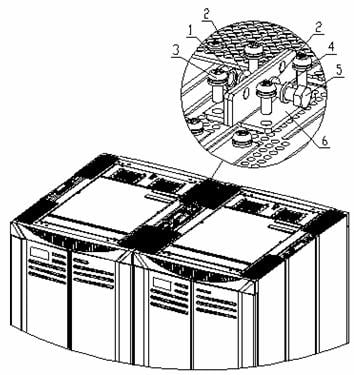
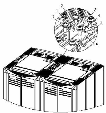
Put the insulation pad under the anchor plate, and then align the plate with the hole of the expansion bolt (one anchor plate needs one insulation pad). Then install the M12×70 bolt in the expansion bolt hole through the anchor plate. Install insulation washer and big flat washers as shown in area A in Figure B-16. Torque the M12x70 bolts to 45 Nm.

|
(1) Bolt M12×70 |
(2) Spring washer 12 |
(3) Big flat washer 12 |
(4) Insulation washer |
|
(5) Insulation pad of the anchor plate |
(6) Expansion tube |
(7) Expansion bolt |
|
|
(8) Nut for fastening the anchor plate |
(9) Anchor plate |
|
|
Figure B-16 Fix the anchor plate
3) Fix the nuts for fastening anchor plates.
Fix the nuts for fastening anchor plates, as shown in area B in Figure B-16.
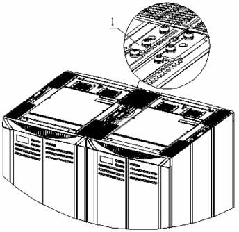
4) Fix cabinet tops when combining cabinets.
If you need to combine two or more cabinets together, related connections need to be performed. Combine the cabinets with connecting plates on the top of the cabinets.
& Note:
If the side panels have been installed, remove the side panels as required before combining the cabinets.
The connecting plates are installed on the top of the cabinets and delivered together with the cabinets, as shown in Figure B-17.
|
(1) Connecting plate for combining cabinets |
Figure B-17 Position of the connecting plate
Remove the connecting plates from the adjacent cabinets, and then reinstall the connecting plates, as shown in Figure B-18.
|
(1) Nut M8 |
(2) Flat washer 8 |
|
(3) Combined screw M6x12 |
(4) Spring washer 8 |
|
(5) Bolt M8x30 |
(6) Connecting plate for combining cabinets |
Figure B-18 Install the connecting plate for combining cabinets
![]() Caution:
Caution:
M8x30 bolts used to combine cabinets are delivered together with support accessories.
IV. Testing insulation
Switch the multimeter to the megohm range and measure the resistance between the fastening bolts M12x70 and the cabinets. If the resistance is larger than 5 megohm, you can finish installation. If not, remove all installation anchor plate components, and then check whether the insulation washers or pads are installed or are damaged. Reinstall the anchor plate and measure insulation until the requirement is satisfied.
Figure B-19 illustrates a single cabinet installed on the cement floor and Figure B-20 illustrates a row of cabinets installed on the cement floor.

Figure B-19 A single cabinet installed on cement floor

Figure B-20 A row of cabinets installed on cement floor
V. Verifying installation
The following requirements must be satisfied:
l Cabinet arrangement, installation positions, and directions must satisfy the requirements of the construction design.
l The front, back, left, and right surfaces of the cabinets should be perpendicular to the floor. The horizontal and vertical tolerance must be less than or equal to 3 mm (0.1 in.).
l The cabinets must be in a straight line near the primary walkway. The tolerance must be less than or equal to 5 mm (0.2 in.). Adjacent cabinets must be closed up. A whole row of cabinets must be flush.
l The surface of the entire row of cabinets should be on the same plane. Adjacent cabinets should be closely arranged.
B.2.2 Installing Cabinets without Feet
Figure B-21 illustrates how to install N68-22 cabinets without feet on cement floor.

Figure B-21 Install cabinets without feet on cement floor
& Note:
l The procedure of combining cabinets is optional.
l When two or more cabinets need to be installed in the same row, they should be installed side by side.
I. Positioning the cabinets
1) Determine where to install the cabinets.
Before installing the cabinet, you need to plan installation space first. Sufficient space must be provided in front of and at the back of the cabinet for maintenance.
2) Make marks.
You can make marks in two ways: determining installation hole positions based on layout design and determining installation hole positions based on the template.
Table B-3 Determine installation hole positions based on the layout
|
Step |
Operation |
Remarks |
|
1 |
Determine the installation positions of the expansion bolts according to the dimensions specified in the construction plan and the installation hole dimensions. |
Figure B-22 shows installation positions of the expansion bolts for a single cabinet. Figure B-23 shows installation positions of the expansion bolts used to combine a row of cabinets. |
|
2 |
Mark several points for drawing with a steel tape, and then draw two straight lines parallel to the benchmarks, with the spacing of 687 mm (27.0 in.). |
— |
|
3 |
Determine the hole positions of the expansion bolts for the first cabinet on the two lines as designed. |
— |
|
4 |
With these holes as reference, mark the installation hole positions of the expansion bolts for other cabinets. |
— |
|
5 |
Measure and confirm hole sizes again. |
— |

Figure B-22 Installation positions of the expansion bolts for a single cabinet

Figure B-23 Installation positions of the expansion bolts used to combine a row of cabinets
Table B-4 Determine installation hole positions based on the template
|
Step |
Operation |
Remarks |
|
1 |
Put the marking template on the floor as required. |
Figure B-24 shows the marking template. |
|
2 |
Mark the positions of all the expansion bolts on the floor according to the template. The semi-circle notch of the template indicates the front of the cabinet. |
Each cabinet needs four expansion bolt holes. |
![]() Caution:
Caution:
Make sure that the template direction is correct.

Figure B-24 Marking template (only for installation on cement floor)
3) Drill holes.
Use M12 expansion bolts to fix supports on the floor. Use a percussion drill with 16 bit to drill holes.
When drilling holes, hold the drill handle firmly with both hands, keeping the bit perpendicular to the floor to prevent damages to the floor or tilted holes.
The depth of the holes should range from 52 mm to 60 mm (2.0 in. to 2.4 in.).All the holes should have the same depth. Clean the holes before measuring their net depth, and then measure the hole depth. After drilling a hole, use a dust collector to clean the dust.
The bit is difficult to position on the floor that is hard and smooth. In this case, punch a small hole on the marks for the installation holes before drilling.
Note that the precision of marking and drilling is essential to hardware installation. Low precision can cause many problems during installation.
![]() Caution:
Caution:
The depth of drilling is between 52 mm and 60 mm (2.0 in. to 2.4 in.). Otherwise, you will be unable to install or fasten the expansion bolts.
4) Install expansion tubes and expansion nuts.
Prior to installation, clean dust inside and outside the holes with a dust collector and then measure the spacing of holes. If errors are not acceptable, you must position and drill the holes again.
Take down the expansion tube and expansion nut, and insert the alignment rib on the expansion nut into the alignment groove of expansion tube. Punch the expansion tube with rubber hammer until the expansion tube is completely buried in the floor. Figure illustrates how to install an expansion nut onto an expansion tube.

|
(1) Expansion tube |
(2) Alignment groove |
(3) Expansion nut |
(4) Alignment rib |
Figure B-25 Install an expansion nut onto an expansion tube
![]() Caution:
Caution:
You must insert the alignment rib of expansion nuts into the alignment grooves of expansion tubes first; otherwise you will be unable to install or fasten the expansion bolts.
II. Leveling the cabinets
1) Put the cabinets in position.
As shown in Figure B-26, put the insulation plates on the ground. Use two insulation plates for each cabinet. Install the cabinets in the planned position and align the installation holes with corresponding expansion bolt holes.
2) Level the cabinets.
Place a horizontal ruler in the two orthogonal directions on the top of the cabinets to check levelness. If the cabinets are not flush, unfasten the retaining nuts of the cabinets on the feet with a shim, and then rotate the screw bolts on the feet to adjust the height of the cabinets until they are flush, as shown in Figure B-26.
|
(1) Cabinet |
(2) Bolt M12 × 70 |
(3) Spring washer 12 |
|
(4) Insulation plate |
(5) Washer |
|
![]() Caution:
Caution:
The washers used to level the cabinets should be installed between the insulation plates and the floor. Insulation will fail if you install the shims between the insulation plates and the cabinets.
III. Fixing cabinets
1) Fix anchor strips.
![]() Caution:
Caution:
To combine two or more cabinets, you need to combine these cabinets before fixing the cabinets.
Screw M12×70 bolts into the holes through the anchor strip, and torque the bolts to 45 Nm. Before that, you must install other accessories such as insulation washers and big flat washers as shown in Figure B-27.
Fasten the bolts one by one to reduce the stress between the bolts and the cabinets.
2) Fix cabinet tops when combining cabinets.
If you need to combine two or more cabinets together, related connections need to be performed. Combine the cabinets with connecting plates on the top of the cabinets.
& Note:
If the side panels have been installed, remove the side panels as required before combining the cabinets.
The connecting plates are installed on the top of the cabinets when they are delivered, as shown in Figure B-27.
|
(1) Connecting plate for combining cabinets |
Figure B-27 Position of the connecting plate
To combine the cabinets, remove the connecting plates from the cabinet, and then reinstall the connecting plates to combine the two adjacent cabinets, as shown in Figure B-28.
![]() Caution:
Caution:
M8x30 bolts used to combine cabinets are delivered together with feet accessories.
|
(1) Nut M8 |
(2) Flat washer 8 |
(3) Combined screw M6x12 |
|
(4) Spring washer 8 |
(5) Bolt M8x30 |
(6) Connecting plate for combining cabinets |
Figure B-28 Install the connecting plate for combining cabinets
IV. Testing insulation
Switch the multimeter to the Megohm range and measure the resistance between the fastening bolts M12×70 and the cabinets. If the resistance is larger than 5 Megohms, you can finish the installation. If not, remove all installation components, and then check whether the insulation components are installed or are damaged. Reinstall the cabinets and test the insulation until the requirement is satisfied.
Figure B-29 illustrates a single cabinet installed on the cement floor and Figure B-30 illustrates a row of cabinets installed on the cement floor.

Figure B-29 Install a single cabinet on the cement floor

Figure B-30 Install a row of cabinets on the cement floor
V. Verifying installation
The following requirements must be satisfied:
l Cabinet arrangement, installation positions, and directions must satisfy the requirements of the construction design.
l The front, back, left, and right surfaces of the cabinets should be perpendicular to the floor. The horizontal and vertical tolerance must be less than or equal to 3 mm (0.1 in.).
l The cabinets must be in a straight line near the primary walkway. The tolerance must be less than or equal to 5 mm (0.2 in.). Adjacent cabinets must be closed up. A whole row of cabinets must be flush.
l The surface of the entire row of cabinets should be on the same plane. Adjacent cabinets should be closely arranged.
B.3 Installing Cabinets on Antistatic Floor
This section describes how to install N68-22 cabinets on antistatic floor.
N800 series supports are required when you install N68-22 cabinets in an equipment room furnished with antistatic floor.
B.3.1 Introduction to Supports and Guide rails
I. Supports
The supports are used to raise the cabinets so as to facilitate flooring and cabling in the equipment room. The supports are welded by steel plates. Insulation pads should be placed under the supports and insulation coverings should be placed around the expansion bolts, so that the equipment is insulated from the ground before grounding cables are connected in order to meet the insulation requirements effectively.
Figure B-31 shows N800 series supports.

|
(1) Upper support |
(2) Antistatic floor height scale |
(3) Lower support |
|
|
(4) Hole through which the support is installed on the ground |
|||
|
(5) Holes connecting guide rails |
|
||
Figure B-31 Outline of N800 series supports
Four types of components are available with the N800 series, three of which are height adjustable and one is height fixed. Table B-5 gives the height range of the height adjustable components.
Table B-5 Height ranges of the height adjustable components
|
Component |
Applicable height of antistatic floor (mm) |
|
I |
210 to 255 |
|
II |
256 to 345 |
|
III |
346 to 525 |
|
IV |
Customized based on the actual floor height. Minimum height: 100 mm (3.9 in.) |
& Note:
The antistatic floor height refers to the distance between the upper surface of the antistatic floor and the cement floor.
The B800 series assemblies I, II, and III all support stepless height adjustment within their adjustable ranges. The adjustment is achieved by the relative movement of the upper and lower supports.
N800 series IV assemblies are fixed supports. They apply to ultra-high and ultra-low floors. The lowest applicable floor height of this assembly is 100 mm.
II. Guide rails
Holder-guide rail components include holder, holder fixing piece, and guide rail. The following sections describe the components:
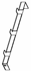
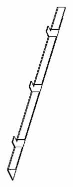
l Holders are used to support the floor around the cabinets. They are divided into front/back holder and side holder.
Figure B-32 and Figure B-33 show the front/back holder and side holder respectively.
l Holder fixing pieces are installed under guide rails. They are used to connect guide rails and front/back holders, as shown in Figure B-34.
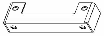
Figure B-34 Holder fixing piece
l Guide rails are used to connect cabinets and supports.
Guide rails allow you to move the device to an appropriate position easily. In addition, they can join multiple racks and cabinets together, make connections stronger and keep the cabinets horizontal. The guide rails also act as a shockproof mechanism for the equipment. Figure B-35 shows the profile of the guide rail.

|
(1) Holes used to connect with supports |
(2) Holes used to connect with cabinets |
Figure B-35 Dimensions of the guide rail
III. Quantity of supports and guide rails
2 × N supports are used to install N cabinets, that is, one N68-22 cabinet uses two supports. N cabinets in one row need 2N supports.
Each cabinet uses a set of components. The components are delivered together with supports. Each set of components consist of two guide rails, two slider holders, two holder fixing pieces, one front holder, and one back holder.
Each cabinet needs two holder fixing pieces, one front holder, and one back holder. Each row of cabinet needs two side holders. When there is only one cabinet in a row, the cabinet also needs two side holders.
B.3.2 Installation Procedure
Figure B-36 shows the procedure for installing cabinets on antistatic floor.

Figure B-36 Install cabinets on the antistatic floor
& Note:
The procedure of combining cabinets is optional.
When two or more than two cabinets need to be installed in the same row, they should be installed side by side.
B.3.3 Positioning Supports
I. Determining where to install the cabinet
Before installing the cabinet, you need to plan installation space first. Sufficient space must be provided in front of and at the back of the cabinet for maintenance.
II. Making marks
You can draw lines in two ways: determining installation hole positions based on layout design and determining installation hole positions based on the template.
Table B-6 Determine installation hole positions based on the layout
|
Step |
Operation |
Remarks |
|
1 |
Determine the installation positions of the supports according to the dimensions specified in the construction plan and the installation hole dimensions |
Figure B-37 shows the installation hole positions of the supports for a single cabinet. Figure B-38 shows the installation hole positions of the supports used to combine a row of cabinets. |
|
2 |
Mark several points for drawing with a steel tape, and then draw two straight lines parallel to the benchmarks, with the spacing of 690 mm (27.0 in.). |
— |
|
3 |
Determine the hole positions of the expansion bolts for the first cabinet on the two lines as designed. |
— |
|
4 |
With these holes as reference, mark the installation hole positions of the expansion bolts for other cabinets. |
— |
|
5 |
Measure and confirm hole sizes again. |
Check whether the supports are aligned with the holes. If errors are not acceptable, you must measure and drill again. |

Figure B-37 Installation hole positions of the support for a single cabinet

Figure B-38 Installation hole positions of the supports used to combine a row of cabinets
Table B-7 Determine installation hole positions based on the marking template
|
Step |
Operation |
Remarks |
|
1 |
Put the marking template on the floor as required. |
Figure B-39 shows the marking template. |
|
2 |
Mark the positions of all the expansion bolts on the floor according to the template. The semi-circle notch of the template indicates the front of the cabinet. |
Each cabinet needs four expansion bolt holes. |
![]() Caution:
Caution:
Make sure that the template direction is correct.

Figure B-39 Marking template (only for installation on antistatic floor)
III. Drilling holes
l Use M12 expansion bolts to fix supports on the ground. Use a percussion drill with Ф16 bit to drill holes.
l When drilling holes, hold the drill handle firmly with both hands, keeping the bit perpendicular to the floor to prevent damages to the floor or tilted holes.
l The depth of the holes should range from 52 mm to 60 mm (2.0 in. to 2.4 in.). All the holes should have the same depth. After drilling a hole, use a dust collector to clean the dust inside and outside the holes before measuring the hole depth.
l The bit is difficult to position on the floor that is hard and smooth. In this case, punch a small hole on the marks for the installation holes before drilling.
l Note that the precision of marking and drilling is essential to hardware installation. Low precision can cause many problems during installation.
![]() Caution:
Caution:
The depth of drilling is between 52 mm and 60 mm (2.0 in. to 2.4 in.). Otherwise, you will be unable to install or fasten the expansion bolts.
B.3.4 Installing Supports
I. Installing expansion bolts
Prior to installation, clean dust inside and outside the holes with a dust collector and then measure the spacing of holes. Check whether the supports are aligned with the holes. If errors are not acceptable, you must measure and drill again.
Take down the expansion tube and expansion nut, and insert the alignment rib on the expansion nut into the alignment groove of expansion tube. Punch the expansion tube with rubber hammer until the expansion tube is completely buried in the floor.
Figure B-40 illustrates how to install an expansion nut onto an expansion tube.

|
(1) Expansion tube |
(2) Alignment groove |
|
(3) Expansion nut |
(4) Alignment rib |
Figure B-40 Install an expansion nut onto an expansion tube
![]() Caution:
Caution:
You must insert the alignment rib of expansion nuts into the alignment grooves of expansion tubes first; otherwise you will be unable to install or fasten the expansion bolts.
II. Adjusting the support height
To ensure that the upper surface of the guide rail is flush with that of the antistatic floor, adjust all the supports to the prescribed heights before installing the supports.
Table B-8 Adjust support height
|
Step |
Operation |
Remarks |
|
1 |
Measure the height of the upper surface of the floor. |
Deduct the height (50 mm: 2.0 in.) of the guide rail from this value. You can get the support height. |
|
2 |
Adjust all the supports to the prescribed heights according to the silk-screen mark of the antistatic floor height on the support. |
— |
|
3 |
Torque the bolts to 45 Nm. |
When fixing a support, fasten the bolts in the middle first and then those at the two sides, as shown in Figure B-41. |

|
(1) Height-retaining bolt (both sides) |
(2) Height-retaining bolt (middle) |
Figure B-41 Fix a rack onto the floor
III. Assembling supports and guide rails
Table B-9 Assemble supports and guide rails
|
Step |
Operation |
|
1 |
Assemble supports and guide rails with M12 x 30 bolts, spring washers, and flat washers, as shown in Figure B-42. |
|
2 |
Adjust supports so that two diagonals A and B (see Figure B-42) are equal. |
|
3 |
Fasten the bolts with a torque wrench. |

|
(1) Support |
(2) Guide rail |
(3) Bolt M12x30 |
|
(4) Spring washer 12 |
(5) Flat washer 12 |
|
Figure B-42 Assemble supports and guide rails
IV. Fixing supports
|
Step |
Operation |
|
1 |
Align the support installation holes with the corresponding expansion bolts and fix the support with M12x60 bolts, spring washers and big flat washers. |
|
2 |
Insert the bolts through the installation holes of the supports into the expansion bolt holes on the floor, and then adjust the positions of the supports. |
|
3 |
Torque the M12x45 bolts to 60 Nm, as shown in Figure B-43. |

|
(1) Bolt M12x60 |
(2) Spring washer 12 |
(3) Flat washer 12 |
|
(4) Expansion tube |
(5) Expansion nut |
|
Figure B-43 Assemble supports and guide rails
In case of combining a row of cabinets, you
must adjust the positions of the supports before fixing them. The front ends of
the supports should be in the same line. The spacing between adjacent supports
should be 128 mm (5.0 in.), as shown in
Figure B-44.

Figure B-44 Position relationship of the supports
B.3.5 Installing Antistatic Floor Accessories
Holders are used to support the antistatic floor around the cabinets. Holder fixing pieces are used to fix holders. Fix holder fixing pieces together with guide rails before positioning the cabinets, as shown in Figure B-45

|
(1) Holder fixing piece |
|
Figure B-45 Install holder fixing pieces
B.3.6 Leveling the Cabinets
I. Putting cabinets in position
Table B-11 Put cabinets in position
|
Step |
Operation |
|
1 |
Lift the cabinet on the guide rails. |
|
2 |
Determine the front side of the cabinet, and then align four installation holes of the cabinet with four holes of the guide rails. |
II. Installing insulation plates
Put two insulation plates on the guide rails for each cabinet, as shown in Figure B-46.

|
(1) Bolt M12x45 |
(2) Spring washer 12 |
(3) Insulation plate |
(4) Washer |
|
(5) Flat washer 12 |
(6) Nut |
(7) Guide rail |
|
Figure B-46 Level and fix a cabinet
III. Levelling the cabinets
|
Step |
Operation |
|
1 |
Place a horizontal ruler in the two orthogonal directions on the top of the cabinets to check levelness. |
|
2 |
If any cabinet is out of levelness, adjust the levelness by using shims under the insulation plate, as shown in Figure B-46. |
|
3 |
Align all the cabinets. The cabinets should be close to the adjacent equipment. They must be in a straight line on the primary walkway side. |
![]() Caution:
Caution:
The spanners used to level the cabinets should be installed between the insulation plates and the guide rails. If you install the spanners between the insulation plates and the cabinets, the spanners do not function.
B.3.7 Fixing Cabinets
I. Fixing anchor strips
|
Step |
Operation |
|
1 |
Fix spring washers on bolts M12x45. Big washers and insulation coverings have been installed in the cabinet. |
|
2 |
Insert the bolts through the lower enclosure frame into the connection holes of the guide rails, and then install the flat washers and the nuts. |
|
3 |
Torque the M12x45 bolts to 45 Nm, as shown in Figure B-46. |
![]() Caution:
Caution:
Fasten the bolts one by one to reduce the stress between the bolts and the cabinets.
II. Fixing cabinet tops when combining cabinets
If you need to combine two or more than two cabinets together, related connections need to be performed. Combine the cabinets with connecting plates on the top of the cabinets.
& Note:
l If the side panels have been installed, remove the side panels as required before combining the cabinets.
l M8x30 bolts used to combine cabinets are delivered together with support accessories.
The connecting plates are installed on the top of the cabinets and delivered together with the cabinets, as shown in Figure B-47.
|
(1) Connecting plate for combining cabinets |
|
Figure B-47 Position of the connecting plate
Remove the connecting plates from the adjacent cabinets, and then reinstall the connecting plates, as shown in Figure B-48.
|
(1) Nut M8 |
(2) Flat washer 8 |
|
(4) Spring washer 8 |
(3) Combined screw M6x12 |
|
(5) Bolt M8x30 |
(6) Connecting plate for combining cabinets |
Figure B-48 Install the connecting plate for combining cabinets
B.3.8 Testing Insulation
Switch the multimeter to the Megohm range and measure the resistance between the supports and the cabinets. If the resistance is larger than 5 megohm, you can finish installation. If not, remove all installation components, and then check whether the insulation washers are installed or are damaged. Reinstall the cabinets and measure insulation until the requirement is satisfied.
B.3.9 Restoring the Floor
I. Installing antistatic floor holders
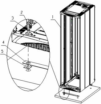
Fix front holders on holder fixing pieces with M12 bolts, spring washers, and flat washers. Fix the side holders on the front holders, as shown in Figure B-49. In case of installing a row of cabinets, you need to install side holders at both ends only.

|
(1) Cabinet |
(2) Guide rail |
(3) Support |
|
(4) Bolt M12x30 |
(5) Spring washer 12 |
(6) Flat washer 12 |
|
(7) Front holder |
(8) Holder fixing piece |
(9) Side holder |
II. Adjusting the height of the antistatic floor holders
Adjust the holder height so that the upper surface of the holder is flush with the lower surface of the antistatic floor.
III. Cutting and restoring the floor
Cut and restore the antistatic floor based on the conditions around the cabinets.
Figure B-50 shows the cabinets installed on the raised antistatic floor.
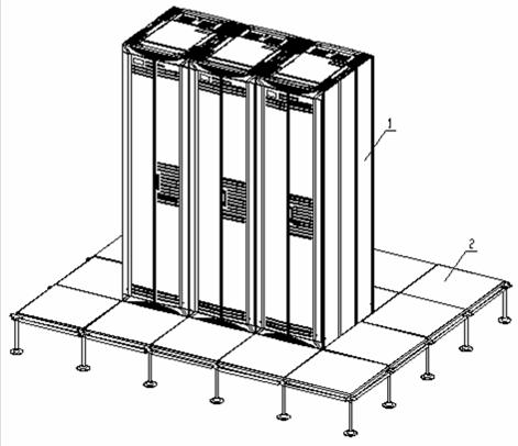
|
(1) Cabinet |
(2) Antistatic floor |
Figure B-50 Cabinets installed on the raised antistatic floor
B.3.10 Verifying Installation
The following requirements must be satisfied:
l The positions of the cabinets must comply with the construction design.
l All the bolts used to fix support and cabinets should be installed stably. Spring washers and flat washers should be installed correctly.
l The insulation accessories between supports and cabinets must satisfy the insulation requirements. Self-made bases are recommended to be insulated from the ground or the cabinets.
l The entire row of cabinets should be arranged closely and neatly. The vertical deviation should be less than 3 mm (0.1 in.)
l The cabinet doors at the primary walkway side should be in a straight line. The error must be less than 5 mm (0.2 in.).
l The surface of the entire row of cabinets should be on the same plane. Adjacent cabinets should be closely arranged.
l All the bolts should be fastened with spring washers and flat washers.
l Make sure that no component is deformed.
B.4 Installing Cabinet Accessories
This section introduces how to install the cabinet accessories.
The accessories include feet, doors, and protection ground cables.
![]() Caution:
Caution:
l Install the feet after unpacking the cabinets and before putting the cabinets in the upright position.
l After installing feet, you must fix the cabinets to avoid accidents.
B.4.1 Installing Feet
Install cabinet feet according to the following procedure:
1) Remove four plastic caps on the lower enclosure frame with a flathead screwdriver.

|
(1) Lower enclosure frame |
(2) Plastic cap |
Figure B-51 Remove plastic caps
2) Install feet.

|
(1) Lower enclosure frame |
(2) Cabinet foot |
(3) Flat washer 6 |
|
(4) Spring washer 6 |
(5) Bolt M6x16 |
|
Figure B-52 Install cabinet feet
Remove the plastic shims and steel shims in the holes on the lower enclosure frame, and then fasten the feet on the lower enclosure frame. Adjust the adjustment nuts on the feet to the required height so that four feet get the same height.
& Note:
l The four feet come in two types, which are identified by R and L respectively. Be sure to choose the correct type in the installation.
l The plastic shims and steel shims remain in the cabinet after installation of the feet. However, they will not affect the normal work of the cabinets.
3) Install cover plates.
After installing the feet, put the cabinet
in the upright position. Press the cover plates in the holes on the lower
enclosure frame, and then fix the cabinet, as shown in
Figure B-53.

|
(1) Cover plate |
(2) Lower enclosure frame |
Figure B-53 Install cover plates
B.4.2 Installing Doors
I. Introduction to doors
Cabinet doors include side panels, front doors, and back doors, as shown in Figure B-54.
Cabinet doors serve as the electromagnetic shielding layer to prevent the devices inside the cabinets from electromagnetic interference. In addition, cabinet doors can protect the devices from being exposed to the outside, which may result in damage to the devices.
Install side panels first, and then install front doors and back doors. Finally stick the product nameplate on the front doors.

|
(1) Front door |
(2) Side panel |
(3) Rack |
Figure B-54 Cabinet components
II. Installation preparations
1) Preconditions
The preconditions of installing cabinet accessories are shown as follows:
l The cabinets have been fixed.
l The devices have been installed.
l The cables have been installed.
2) Installation materials
Installation materials consist of:
l Two left side panels and two right side panels
l Two front doors and two back doors. Front door and back doors are the same. They are of the dual-door structure.
l M6 countersunk screws
3) Install a side panel
Side panels are necessary for both ends of a row of cabinets. Side panels fall in left ones and right ones. A pair of side panels needs to be installed at both ends of a row of cabinets. They are installed at both sides of the cabinet columns.
Figure B-55 shows the installation of a side panel. The following table describes the operation procedures:
Table B-14 Install a side panel
|
Step |
Operation |
|
1 |
Loosen M6 bolts used to connect the side panel on the cabinet column, and then put the side panel between the door lintel and the column. |
|
2 |
Set the socket of the side panel onto the pin (M6 bolt) from above the pin, and then install the side panel into the open socket of the installation rack. |
|
3 |
Align the side panel with the installation holes, and then fasten four M6 countersunk screws to fasten the side panel with a flathead screwdriver. |

Figure B-55 Install a side panel
4) Install front and back doors
Front doors and back doors are the same. They are of the dual-door structure.
Figure B-56 shows the installation of a front/back door. The following table describes the operation procedures:
Table B-15 Install a front/back door
|
Step |
Operation |
|
1 |
Hold the door so that the cross-pin on the rack is in line with the hole at the lower right side of the door and then put the lower part of the left side also in position. |
|
2 |
Pull down the triangular hook pin of the upper part of the door. Align the hole on the door with the hole on the top of the rack. |
|
3 |
Release the hook pin so that with the elastic force the hook pin locks into the hole and fastens the door onto the cabinet. |

|
(1) A: Hold the door so that the cross-pin on the rack is in line with the hole at the lower right side of the door and then put the lower part of the left side also in position. |
|
(2) Pull down the triangular hook pin of the upper part of the door. Align the hole on the door with the hole on the top of the rack. Release the hook pin so that the hook pin locks into the hole and fastens the door onto the cabinet. |
Figure B-56 Install front door and back door
& Note:
l Hook pins have been installed on the doors before delivery.
l After installing the front door, stick the product label in the concave position of the front door.
l The bag of the cabinet door keys contains leveling shims. When necessary, use the shims around the bottom pivot pins of the front and back doors to adjust the levelness of the doors.
B.4.3 Installing Protection Ground Cables
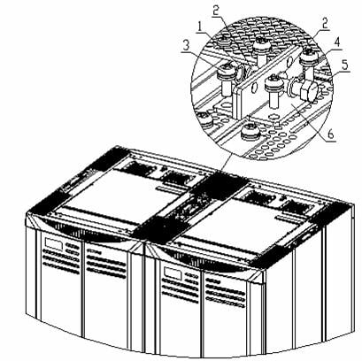
After installing side panels, front doors, and back doors, install protection ground cables near the lower hook pins so that the doors can be reliably grounded. The protection ground cables connect grounding points with grounding screws on the cabinet base, as shown in Figure B-57.
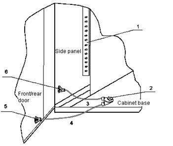
|
(1) Grounding bar of the side bracket |
(2) Grounding point on the cabinet base |
|
(3) Protection ground cable for the side panel |
|
|
(4) Protection ground cable for the front and back doors |
|
|
(5) Grounding points on front and back doors |
(6) Grounding point on the side panel |
Figure B-57 Connect protection ground cables
As shown in Figure B-57, there are four protection ground cables of the side panel in the lower part of the cabinet. These cables connect the grounding points of four side panels and those of the cabinet base respectively.
Connect the protection ground cables to the grounding points of the front and back doors and the grounding point of the cabinet base. Connect the ground cables to the front side, back side, left side, and right side of the lower part of the cabinet respectively. Install the protection grounding cables after installing the cabinet doors.
B.5 Introduction to Cabinet Cable Management
This section introduces cable management for N68 cabinets, including introduction to the cabinet grounding points and internal cable management.
B.5.1 Introduction to Cabinet Grounding Points
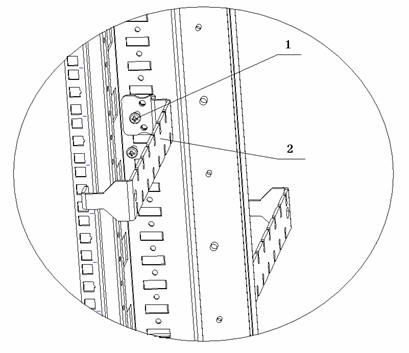
I. Grounding points connecting the cabinet and the modules
l The grounding points of the internal modules are reserved on both sides of the back mount angle. Two types of grounding points are available: M4 and M6. They should be installed alternatively. The spacing between two grounding points of the same specification is 133.35 mm (5.3 in.), as shown in Figure B-58 (1).
l The main grounding point used to connect the module and the cabinet is located at the back of the upper enclosure frame. The specification is M6, as shown in Figure B-58 (2).

|
(1) Grounding points used to connect the internal modules and the cabinet |
|
(2) Main grounding points of the internal modules |
Figure B-58 Grounding points of internal modules
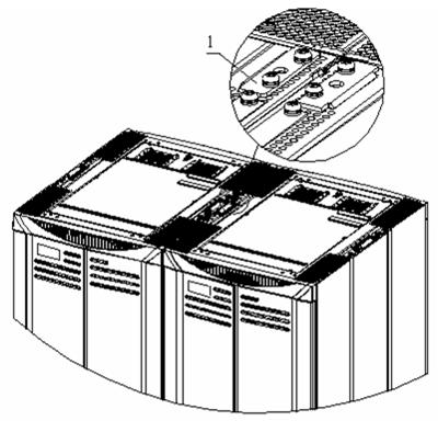
II. Main grounding point
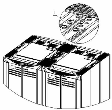
Main grounding point used to connect the cabinet and the equipment room is located on the cabinet top. The specification is M8, as shown in Figure B-59.

|
(1) Main grounding point |
|
Figure B-59 Main grounding point
B.5.2 Introduction to Cabinet Power Distribution
& Note:
Only maintenance engineers are permitted open the cabinet door with the key.
I. Power distribution diagram for an N68 AC cabinet

Figure B-60 Power distribution diagram for an N68 AC cabinet
& Note:
l This diagram is for S7500 AC cabinets only.
l The Brown wire is the live wire L; Blue wire is the neutral wire N; Yellow green wire is the earth wire PE.
l An AC cabinet supports dual 220 VAC inputs. Each input first connects to one 32 A bipolar NCB and then to three 16 A bipolar NCBs to supply power to devices.
l 220 VDC power is dangerous. When the cabinet is in operation, the cabinet door should be locked by professional maintainers, and the maintainers should pay attention not to touch any of the power terminals during maintenance.
l Point 1, 2, 3 in the diagram each represents a device.
l If you use dual AC power outputs (with out-phase L, N), and the device in the cabinet support dual-input power supply, you are recommended to connect the two inputs of the device to two NCBs with different AC input. If there are more than three devices in the cabinet, you can parallel connect several devices to one NCB, with proper consideration of the device power.
l If your device power is small, the device is protected by its own power protection set or the superior air breaker rather than the NCB. You can change the NCB, but H3C does not provide NCBs of various capacities.
l Two sets of power distribution components locate at the front and rear of the cabinet respectively.
II. Power distribution diagram for an N68 DC cabinet

Figure B-61 Power distribution diagram for an N68 DC cabinet
& Note:
l This diagram is for S7500 DC cabinets only.
l The DC cabinet supports dual -48 VDC power inputs, each -48 V input supplies power to devices through three unipolar NCBs (63 A).
l High DC voltage is dangerous. When the cabinet is in operation, the cabinet door should be locked by professional maintainers, and the maintainers should pay attention not to touch any of the power supply terminals during maintenance.
l Point 1, 2, 3 in the diagram each represents a device.
l If you use dual -48 VDC power outputs, and the device in the cabinet support dual-input power supply, you are recommended to connect the two inputs of the device to two -48 V NCBs. If there are more than three devices in the cabinet, you can parallel connect several devices to one NCB, with proper consideration of the device power.
l If you use a single -48 VDC power output, you can connect the output to the two input terminals.
l If your device power is small, the device is protected by its own power protection set or the superior air breaker rather than the NCB. You can change the NCB, but H3C does not provide NCBs of various capacities.
l The power distribution component is in the rear of the cabinet, you can remove it to the front of the cabinet as needed.
l You can connect the PE of a device to the busbar at the side of the cabinet, or to the PGND terminal at the power distribution component.
B.5.3 Introduction to Internal Cable Management
I. Introduction to cable management components
l 1U cabling frame, used for organizing collected cables at the rear of the cabinet to facilitate the user to manage power cables, in most situations, and data cables. When using a 1U cabling frame, put the cables of the accessories through the cabling brackets, lead them to the rear side of the cabinet, and bundle the cables at the proper positions with cable ties.

|
(1) Cabling brackets |
|
l 2U cabling frame, which functions similarly as a 1U cabling frame while supporting a larger number of cables. It is mostly used for data cables. Following a similar method of using a 1U cabling frame, lead the cables from both sides into the cabling brackets and then to the rear side of the cabinet through two oval openings, and bundle the cables at the proper positions with cable ties.

|
(1) Cabling brackets |
(2) Oval cable opening |
& Note:
You can move the positions of the 1U and 2U cabling frames as required. If necessary, you can also remove the adjacent dummy panel to facilitate cabling.
A 1U rear cable management bracket is installed at the back of the cabinet, used together with a power socket strip for management of power cables. When using a 1U rear cable management bracket, put the cables on the cable holding hooks, and bundle the cables at the proper positions with cable ties.

|
(1) Cabling holding hook |
(2) Cable binding hole |
Figure B-64 1U rear cable management bracket
l Mounted at both sides of the cabinet, cable retaining brackets are used for management of bundled cables inside the cabinet. When using a cable retaining bracket, arrange the collected cables in order and lay them in the cable retaining bracket, and bundle the cables at the proper positions with cable ties.

Figure B-65 Cable retaining bracket
& Note:
You can move the positions of cable retaining brackets in the cabinet required. For the specific method, refer to Figure B-66.
|
(1) Tapping screw |
(2) Cable retaining bracket |
Figure B-66 Move a cable retaining bracket
To move a cable retaining bracket, remove the tapping screw from the cable retaining bracket, move the cable retaining bracket to the desired position in the cabinet, and fasten the cable retaining bracket with the same tapping screw.
II. Introduction to cabling holes
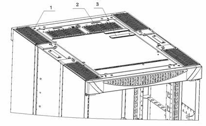
l Cabling holes on the upper enclosure frame
|
(1) Corner cabling hole |
(2) Rear cabling hole |
(3) Middle cabling hole |
Figure B-67 Cabling holes on the upper enclosure frame
l Cabling holes on the lower enclosure frame

|
(1) Rear cabling hole |
(2) Corner cabling hole |
Figure B-68 Cabling holes on the lower enclosure frame
B.6 Remodeling Cabinets
B.6.1 Remodeling an S7500 N68-18 Cabinet

Figure B-69 Remodel an S7500 N68-18 cabinet
& Note:
l In the figure: (1) indicates a dummy panel; (2) indicates a cabling frame; (3) indicates a nonstandard mini panel.
l Small squares in the figure indicate guide rails. A1 through G1 and A2 through G2 are guide rails at the corresponding positions.
l M1 through M10 indicate dummy panels at the corresponding positions in the standard configuration.
l In a DC cabinet, you may need to remove the M10 in the upper most, and move the DC power distribution component that is originally located at the rear of the cabinet to this position.
l In AC cabinets, no M10 exists, and the position is for the AC power distribution component.
l The S7500 series and other devices that comply with the N68 cabinet size can be installed in the cabinet.
l You do not need to use the cabinet exactly as the figure shows, but can adjust the positions of guide rails and dummy panels as needed.
l Dummy panels are installed for comeliness purpose only, so you do not need to install them when they are in shortage.
l The power of your device should be within the range allowed by the air breaker. Refer to power distribution part for details.
l The squares with shadow marks in the figure represent the four-hole guide rails, which can bear a weight of 90 KG; and the squares without shadow marks represent the two-hole guide rails, which can bear a weight of 40 KG.
|
Symbol |
Description |
|
S |
Indicates standard configuration (configured with one S7503 chassis) |
|
A |
Configured with two S7503 chassis |
|
B |
Configured with one S7506 chassis |
|
C |
Configured with one S7506R chassis |
The methods of remodeling standard configuration to other configuration are as follows:
1) Remodeling standard configuration to configuration A: Remove dummy panels M7 and M8, and remove the guide rails F1 and F2. The result of the remodeling is configuration A.
2) Remodeling standard configuration to configuration B: Remove dummy panels M3 and M4, and remove guide rails C1 and C2. The result of the remodeling is configuration B.
3) Remodeling standard configuration to configuration C: Remove dummy panels M3, M4, and M6, remove guide rails C1, C2, E1, and E2, and raise one U up the guide rails D1 and D2 together with the 2U-high cabling frame above, and the M5 below The result of the remodeling is configuration C.
B.6.2 Remodeling an S7500 N68-22 Cabinet

Figure B-70 Remodel an S7500 N68-22 cabinet
& Note:
l In the figure: (1) indicates a dummy panel; (2) indicates a cabling frame; (3) indicates a nonstandard mini panel
l Small squares in the figure indicate guide rails.
l A1 through H1 and A2 through H2 are guide rails at the corresponding positions.
l M1 through M13 indicate dummy panels at the corresponding positions in the standard configuration.
l In a DC cabinet, you may need to remove the M13 in the upper most, and move the DC power distribution component which originally locates at the rear of the cabinet to this position.
l In AC cabinets, M13 does not exist, and the position is for the AC power distribution component.
l The S7500 series and other devices that comply with the N68 cabinet size can be installed in the cabinet.
l You need not to use the cabinet exactly as the figure shows, but can adjust the position of guild rails and dummy panels as needed.
l The dummy panels are for comeliness purpose only, so that you need not to install them when they are in shortage.
l The power of your device should be within the range allowed by the air breaker. Refer to power distribution part for details.
l The squares with shadow marks in the figure represent the four-hole guide rails, which can bear a weight of 90 KG; and the squares without shadow marks represent the two-hole guide rails, which can bear a weight of 40 KG.
|
Symbol |
Description |
|
S |
Indicates standard configuration (configured with one S7503 chassis) |
|
A |
Configured with two S7503 chassis |
|
B |
Configured with one S7506 chassis |
|
C |
Configured with two S7506 chassis |
|
D |
Configured with one S7506R chassis |
|
E |
Configured with two S7506R chassis |
The methods of remodeling standard configuration to other configuration are as follows:
1) Remodeling standard configuration to configuration A: Remove dummy panel M7 and M8. The result of the remodeling is configuration A.
2) Remodeling standard configuration to configuration B: Remove dummy panels M2 and M3, remove guide rails C1 and C2. The result of the remodeling is configuration B.
3) Remodeling standard configuration to configuration C: Remove dummy panels M2, M3, M7 through M10, and remove guide rails C1, C2, G1 and G2. The result of the remodeling is configuration C.
4) Remodeling standard configuration to configuration D: Remove dummy panels M2, M3, and M4, remove guide rails C1 and C2. The result of the remodeling is configuration D.
5) Remodeling standard configuration to configuration E: Remove dummy panels M2, M3, M4, M7 through M11, and remove guide rails C1, C2, G1, and G2. The result of the remodeling is configuration E.