- Table of Contents
-
- H3C S7500 Series Ethernet Switches Installation Manual-(V1.02)
- 00-1Cover
- 01-Chapter 1 Product Overview
- 02-Chapter 2 Line Processing Units
- 03-Chapter 3 Installation Preparations
- 04-Chapter 4 Hardware Installation
- 05-Chapter 5 System Commissioning
- 06-Chapter 6 Hardware Maintenance
- 07-Chapter 7 Software Maintenance
- 08-Chapter 8 Troubleshooting
- 09-Appendix A B68-22 Cabinet Installation
- 10-Appendix B N68 Cabinet Installation
- 11-Appendix C Lightning Protection
- 12-Appendix D AC Power Cables Used in Different Countries or Regions
- Related Documents
-
| Title | Size | Download |
|---|---|---|
| 05-Chapter 5 System Commissioning | 287.02 KB |
Table of Contents
Chapter 5 System Commissioning
5.1 Configuration Environment Setup
5.1.1 Setting up Networking Environment
5.1.2 Connecting the Console Cable
5.1.3 Setting Terminal Parameters
5.2.3 Check after Power-on (Recommended)
Chapter 5 System Commissioning
5.1 Configuration Environment Setup
5.1.1 Setting up Networking Environment
l The terminal (a PC in this example) is connected to the console port of the switch with a console cable.

Figure 5-1 Network diagram for switch configuration
5.1.2 Connecting the Console Cable
Follow these steps to connect the console cable:
1) Connect the DB-9 female connector of the console cable to the serial port of the PC.
2) Connect the RJ-45 connector of the console cable to the console port of the switch.
5.1.3 Setting Terminal Parameters
Parameter requirements:
l Bits per second: 9600
l Data bits: 8
l Parity check: None.
l Stop bits: 1.
l Flow control: None.
l Terminal emulation: VT100.
The following illustrates how to set terminal parameters on the PC running Windows XP HyperTerminal.
Step 1: Start the PC and run the terminal emulator.
Step 2: Set the parameters for Windows XP HyperTerminal as follows:
l Bits per second: 9600
l Data bits: 8.
l Parity check: None
l Stop bits: 1
l Flow control: None
l Terminal emulation: VT100
The parameter setting procedure is as follows:
1) Select Start > Programs/All Programs > Accessories > Communications > HyperTerminal to enter the HyperTerminal window to establish a new connection and the system displays the Connection Description dialog box.
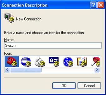
Figure 5-2 Connection description of HyperTerminal
2) Enter the name of the new connection in the Connection Description dialog box and click OK. Then the system displays the Connect To dialog box.
3) Select the serial port to which the cable is connected from Connect using dropdown list.
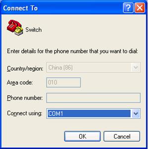
Figure 5-3 Select the serial port for hyper terminal connection
4) Click OK. The system displays the serial port parameters setting dialog box as shown in Figure 5-4.
5) Set the bits per second to 9600, data bits to 8, parity check to none, stop bits to 1 and flow control to none.
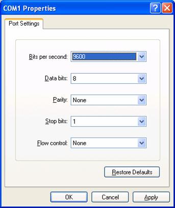
Figure 5-4 Set the serial port parameters
6) Click OK. The system enters the HyperTerminal dialogue box as shown in Figure 5-5.
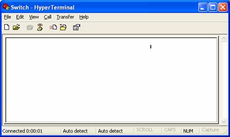
Figure 5-5 HyperTerminal dialog box
7) In the HyperTerminal dialogue box, click the properties icon to open the Switch Properties dialog box.
8) Click the Settings tab, set the terminal emulation to VT100, and click OK (see Figure 5-6).

Figure 5-6 Set the terminal emulation
5.2 Power-on Startup
5.2.1 Check before Power-on
Before powering on the switch, make sure that:
l The switch is mounted steadily.
l All boards are correctly installed.
l All communication cables, fibers, power cables, and grounding cables are correctly connected.
l The power outlet voltage is the same as the one indicated on the switch label.
l The console cable is correctly connected, the PC or terminal for configuration is started, and the terminal parameter settings are completed.
![]() Caution:
Caution:
Before powering on the switch, locate the position of the power switch for the equipment room where you will operate so that you can switch off the power supply promptly in case of any accident
5.2.2 Power-on
l Turn on the power to the system.
l Turn on the power switch on the system.
5.2.3 Check after Power-on (Recommended)
After powering on the switch, check that:
l The cooling system works normally. You can hear the fans rotate and feel airflows out of the vent.
l The system LEDs on the SRPU work normally.
After that, make corresponding configurations.
5.2.4 Startup Process
As the switch is started, the following information will be output on the configuration terminal:
& Note:
The following information may vary with switch models.
******************************************
* *
* H3C S7506 BOOTROM, Version 530 *
* *
******************************************
Copyright(c) 2004-2007 Hangzhou H3C Tech. Co., Ltd.
Creation date : Apr 20 2007, 14:48:52
CPU type : MPC8245
CPU Clock Speed : 300Mhz
BUS Clock Speed : 33Mhz
BOOT_FLASH type : M29W040B
Flash Size : 32MB
Memory Size : 256MB
S7506 main board self testing................................
SDRAM Data lines Selftest.................................OK!
SDRAM Address lines Selftest..............................OK!
SDRAM fast selftest.......................................OK!
Please check LEDs.....................LEDs selftest finished!
CPLD selftest.............................................OK!
FPGA selftest.............................................OK!
The switch Mac address is .....................0000.0309.0004
Press Ctrl+B to enter Boot Menu... 5
Auto-booting...
Auto booting file is srpuprj.app
Decompress Image...................................................
.......................................................OK!
Starting at 0x60000...
..........................................................................
..........................................................................
..........................................................................
....................
User interface Aux0/0 is available
Press ENTER to get started.
The display of the above information indicates the completion of the switch auto-startup.
Press Enter. The following prompt appears on the configuration terminal, which indicates that you can start configuring the switch.
<H3C>
& Note:
H3C S7500 series switches provide a variety of command views. For the specific descriptions on the configuration commands and command line interfaces, refer to H3C S7500 Series Ethernet Switches Operation Manual and H3C S7500 Series Ethernet Switches Command Manual.