- Table of Contents
-
- H3C S7500 Series Ethernet Switches Installation Manual-(V1.02)
- 00-1Cover
- 01-Chapter 1 Product Overview
- 02-Chapter 2 Line Processing Units
- 03-Chapter 3 Installation Preparations
- 04-Chapter 4 Hardware Installation
- 05-Chapter 5 System Commissioning
- 06-Chapter 6 Hardware Maintenance
- 07-Chapter 7 Software Maintenance
- 08-Chapter 8 Troubleshooting
- 09-Appendix A B68-22 Cabinet Installation
- 10-Appendix B N68 Cabinet Installation
- 11-Appendix C Lightning Protection
- 12-Appendix D AC Power Cables Used in Different Countries or Regions
- Related Documents
-
| Title | Size | Download |
|---|---|---|
| 09-Appendix A B68-22 Cabinet Installation | 2.59 MB |
Table of Contents
Appendix A B68-22 Cabinet Installation
A.1 Installation Requirements and Flowchart
A.2 Mounting the Cabinet on Cement Floor
A.2.1 Components of an Integrated Anchor Plate
A.3 Mounting Cabinets on the Antistatic Floor
A.3.2 Introduction to Slide Rails
A.3.6 Installing the Slide Rails
A.3.7 Installing Antistatic Floor Supports
Appendix A B68-22 Cabinet Installation
The S7500 series can be installed in a B68-22 cabinet. The cabinet dimensions are 2200 × 600 × 800 mm (86.6 × 23.6 × 31.5 in.) and the weight is 130 kg (286.6 lb).
A.1 Installation Requirements and Flowchart
A.1.1 Site Planning
Plan the installation site before installing the cabinet, reserving adequate clearance around the cabinet for operation and maintenance. Figure A-1 shows the layout of a single cabinet and Figure A-2 shows the layout of combined cabinets.
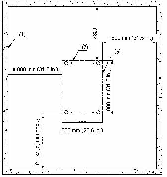
|
(1) Inner wall or reference |
(2) Cabinet rear |
(3) Cabinet side |
Figure A-1 Layout of a single cabinet
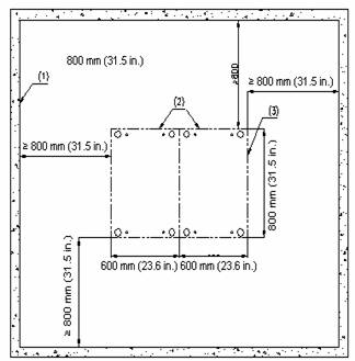
|
(1) Inner wall or reference |
(2) Cabinet rear |
(3) Cabinet side |
Figure A-2 Layout of combined cabinets
A.1.2 Installation Flowchart
You can mount the B68-22 cabinet on cement floor or antistatic floor. Figure A-3 shows the B68-22 cabinet installation flowchart.

Figure A-3 B68-22 cabinet installation flowchart
![]() Caution:
Caution:
l Before installation, ensure that the site is correctly marked to avoid rework.
l Be careful to move the cabinet and avoid damaging the boards and cables in the cabinet.
l Unpack the cabinet, remove the two side panels from the cabinet with a Phillips screwdriver, put them away in a safe area to avoid damage, and keep the removed screws.
l Check the installation and clean the area after you install the cabinet.
A.2 Mounting the Cabinet on Cement Floor
To mount the B68-22 cabinet on cement floor, use integrated anchor plates to fasten the cabinet feet. The height of the feet is adjustable in consideration of uneven floor.
![]() Caution:
Caution:
The feet are insulated and the anchor plates contain insulating parts. Correctly install the insulating parts to insulate the equipment from the earth ground before it is grounded.
A.2.1 Components of an Integrated Anchor Plate
Figure A-4 illustrates an integrated anchor plate for the B68-22 cabinet. Figure A-5 illustrates how to install the anchor plate and the cabinet feet.

|
(1) Slot for fixing the foot |
(2) Hole for fixing the anchor plate |
Figure A-4 Integrated anchor plate

|
(1) Foot bolt |
(2) Lock nut for cabinet |
(3) Lock nut for anchor plate |
|
(4) M12 stud, 70 mm (2.76 in) long |
(5) M12 spring washer |
(6) M12 flat washer |
|
(7) Insulation washer |
(8) Insulation washer |
(9) Expansion tube |
|
(10) Expansion nut |
(11) Integrated anchor plate |
|
Figure A-5 Components of the integrated anchor plate
A.2.2 Installation Flow
The installation of cabinets on cement floor involves these steps:
1) Position the cabinets
2) Level the cabinet
3) Combine the cabinets
4) Fix the cabinets
5) Test insulation.
Figure A-6 shows the cabinet installation flowchart on cement floor.

Figure A-6 Cabinet installation flowchart on cement floor
A.2.3 Positioning Cabinets
I. Marking
According to the reference dimensions and the positions of foot bolts in the cabinet layout, determine the mounting holes as follows:
1) Use an ink fountain to draw two parallel lines, with a distance of 720 cm (28.35 in) between them and a distance of more than 800 cm (31.50 in) away from the nearest wall.
2) Determine the mounting holes on the two lines for the first cabinet according to the design requirements. Using these mounting holes as a benchmark, determine the mounting holes for the other cabinets in turn.
Re-measure the dimensions to prevent mistakes. Figure A-7 and Figure A-8 illustrate the layout of mounting holes and foot bolts for a single cabinet and two cabinets respectively.
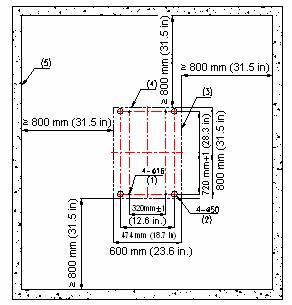
|
(1) M12 expansion bolt |
(2) Position of foot bolt |
(3) Cabinet side |
|
(4) Cabinet rear |
(5) Inner wall or reference |
|
Figure A-7 Layout of the mounting holes and foot bolts (single cabinet)
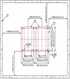
|
(1) M12 expansion bolt |
(2) Position of foot bolt |
(3) Cabinet side |
|
(4) Cabinet rear |
(5) Inner wall or reference |
|
Figure A-8 Layout of the mounting holes and foot bolts (two cabinets)
II. Drilling holes
Use a percussion drill with a F16 bit to drill holes for bolting the anchor plates.
When drilling holes, hold the drill handle firmly with both hands, keeping the bit perpendicular to the floor to prevent floor destruction and tilted holes.
All the holes must have a depth of 52 to 60 mm (2.0 to 2.4 in.). Use a vacuum cleaner to clean the holes before measuring the depth.
If it is difficult to position the bit on hard, smooth floor, punch a small hole on the marks before drilling.
Note that the precision of marking and drilling is essential to hardware installation. A low precision can cause many problems during installation.
![]() Caution:
Caution:
The holes must be 52 to 60 mm (2.0 to 2.4 in.) deep. Otherwise, you will be unable to fasten the expansion bolts.
III. Installing expansion tubes and nuts
Before installing expansion bolts, clean dust inside and around the holes with a vacuum cleaner and then measure the spacing of holes. If the error is unacceptable, you need to re-locate and drill mounting holes.
Follow these steps to install expansion tubes and nuts:
1) Remove the expansion tube and nut from an expansion bolt.
2) Mount the expansion tube on the expansion nut, with the guide ribs aligned with the guide grooves.
3) Insert the expansion tube into a hole vertically.
4) Tap the expansion tube with a rubber hammer until the expansion tube completely goes into the hole.
5) Repeat step 1 through step 4 to install other expansion tubes and nuts.
Figure A-9 illustrates how to mount an expansion tube on an expansion nut.

|
(1) Expansion tube |
(2) Guide groove |
|
(3) Expansion nut |
(4) Guide nut |
Figure A-9 Mount an expansion tube on an expansion nut.
![]() Caution:
Caution:
You must insert the guide ribs on the expansion nuts into the guide grooves on expansion tubes. Otherwise, you will be unable to install or fasten the expansion bolts.
A.2.4 Levelling Cabinets
I. Positioning Cabinets
After finishing marking, move the cabinet to the planned location with its feet aligning with the corresponding feet marks.
II. Adjusting Cabinet Feet
Place two horizontal rulers perpendicular to each other on the top of the cabinet to check that the cabinet is straight. Adjust the cabinet feet with a spanner to have the cabinet perpendicular to the ground. Fasten the retaining nuts on the feet to have the retaining nut closely meet the downside of the cabinet. Figure A-10 shows how to lock cabinet feet.

|
(1) Cabinet retaining nut |
(2) Cabinet foot |
|
(3) Anchor strip retaining nut |
(4) Downside of the cabinet |
A.2.5 Combining Cabinets
Skip this section if you only install one cabinet.
If multiple cabinets are used, follow these steps to connect them together.
1) Remove the cabinet covers as shown in Figure A-11.
2) Rotate the combining brackets on top of the cabinets by 180 degrees, tighten them, and connect the cabinets with flat washers, spring washers, bolts and nuts, as shown in Figure A-12.
3) Figure A-11 illustrates the original position of the combining brackets and Figure A-12 illustrates the position after they are rotated.

|
(1) Upper frame of the cabinet |
(2) Combining bracket |
|
(3) M6 × 10 bolt |
(4) Cabinet cover |
Figure A-11 Remove/install the cover

|
(1) M8 nut |
(2) Flat washer 8 |
(3) Spring washer 8 |
|
(4) M8 × 35 bolt |
(5) Combining bracket |
|
Figure A-12 Install brackets for combining cabinets
![]() Caution:
Caution:
After you combine the cabinets, replace the removed covers.
A.2.6 Fixing Cabinets
I. Installing anchor strips
As shown in Figure A-13, install the anchor strips. One chassis needs two anchor strips.
![]() Caution:
Caution:
The anchor strip must be installed in the orientation as shown in Figure A-13.

|
(1) Anchor strip retaining nut |
(2) M16 cabinet foot |
(3) Anchor strip |
Figure A-13 Install anchor strips
II. Installing insulating parts and fixing the anchor strips
Follow these steps to install insulating parts and fix an anchor strip:
1) Put the insulating washers under the anchor strip and align them vertically with the anchor strip fixing holes (one anchor strip needs two insulating washers).
2) Screw M12 × 70 bolts into the holes through the anchor strip, and Torque the bolts to 45 Nm. Before that, you must install other accessories such as insulation washers and big flat washers as shown in area A in Figure A-14.

|
(1) Anchor strip retaining nut |
(2) Anchor strip |
(3) Cabinet foot |
|
(4) Insulating washer of the strip |
(5) M12 × 70 bolt |
(6) Spring washer 12 |
|
(7) 12 big flat washer |
(8) Insulation washer |
(9) Expansion tube |
|
(10) Expansion nut |
|
|
Figure A-14 Install anchor strips
III. Fixing the retaining nuts of the anchor strips
Fasten the retaining nut on the anchor strip as shown in area B in Figure A-14.
A.2.7 Testing Insulation
Switch the multimeter to Mohm range and measure the resistance between the fastening bolts M12 × 70 and the anchor strips.
If the resistance is larger than five Mohm, you can finish installation. If not, remove all anchor strip parts, check that the insulation washers are installed and without damage, reinstall, and measure insulation until the requirement is satisfied. Figure A-15 and Figure A-16 illustrate how to install a single and two cabinets on the cement floor respectively.

Figure A-15 Install a single cabinet on cement floor

Figure A-16 Install two cabinets on cement floor
A.3 Mounting Cabinets on the Antistatic Floor
When mounting B68-22 cabinets on the antistatic floor, use the H800 series racks.
![]() Caution:
Caution:
The feet are insulated, and the anchor strips include insulating units. Correctly install the insulating units to insulate the equipment from the earth ground before it is grounded.
A.3.1 Introduction to Racks
Racks are used for raising cabinets for flooring and cabling sake. They are made of steel sheets. Insulation can be ensured however, because the cabinet feet are insulated and the anchor strips include insulation parts. Before connecting the grounding wire, the equipment does not conduct with the earth ground.
I. Number of racks in use
When installing multiple cabinets, you need to use N+1 racks, where N is the number of cabinets, as shown in Figure A-17.

Figure A-17 Mount a cabinet on the slide rails on a rack
II. Shape of racks
Figure A-18 illustrates an H800 series rack.

|
(1) Upper rack |
(2) Lower rack |
|
(3) Floor-mounting slot |
(4) Slot for connecting to the slide rail |
|
(5) Silkscreen of antistatic floor height |
|
Figure A-18 Outer dimensions of the H800 series
III. Installing rack components
Four types of components are available with the H800 series, three of which are height adjustable and one is height fixed. Table A-1 gives the height range of the height adjustable components.
Table A-1 Height ranges of the height adjustable components
|
Component |
Height of antistatic floor (mm) |
|
Ⅰ |
210 to 255 mm (8.27 to 10.0 in.) |
|
Ⅱ |
256 to 345 mm (10.1 to 13.6 in.) |
|
Ⅲ |
346 to 525 mm (13.6 to 20.7 in.) |
|
Ⅳ |
Customized according to floor height min: 100 mm (3.9 in.) |
& Note:
The height of the antistatic floor refers to the distance between the upside of the antistatic floor and cement floor.
The components I, II and III allow you to adjust height freely within the specified ranges by moving oppositely the upper and lower racks.
The IV component is for racks with fixed heights that are extremely high or low. The lowest floor height must be 100 mm (3.9 in).
A.3.2 Introduction to Slide Rails
Slide rails allow you to move the device to an appropriate position easily. In addition, they can join multiple racks and cabinets together, make connections stronger and keep the cabinets horizontal. As shown in Figure A-19, a slide rail segment is 600 mm (23.6 in.) long. The standard shipment includes two segments for each cabinet.

Figure A-19 Dimensions of slide rail segments
A.3.3 Installation Flow
Installing the cabinet on cement floor includes these steps: Position the racks. Install the racks. Install the slide rails. Install the floor support accessories. Level the cabinets. Combine cabinets. Fix the cabinets. Test insulation. Replace the antistatic floor. The installation flow is shown in Figure A-20.
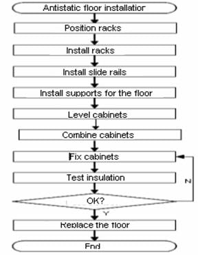
Figure A-20 Mounting Cabinets on the Antistatic Floor
A.3.4 Positioning Racks
I. Determining where to install the cabinet
You must determine where to install the cabinet according to the benchmark specifications provided in the footprint and outer dimensions of the cabinet.
II. Marking
According to the footprint and outer dimensions of the cabinets and dimensions of racks, do the following:
1) Use an ink fountain to draw two parallel lines, with a distance of 720 cm (28.35 in) between them and a distance of more than 800 cm (31.50 in) away from the nearest wall.
2) Draw two lines parallel with the reference and 760 mm (29.9 in.) away from each other with an ink fountain.
3) According to the design, mark the position of the installation holes for a rack on these two lines. Based on the marks, mark the position of other rack installation holes.
4) Verify marking and sizes to prevent mistakes.
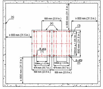
5) Figure A-21 illustrates the layout of the rack installation holes. Figure A-22, Figure A-23 and Figure A-24 illustrate the layout of the mounting holes for a single, two and multiple cabinets respectively.
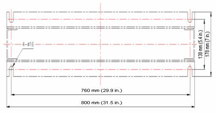
Figure A-21 Layout of the installation holes on the H800 series racks
|
(1) M12 expansion bolt |
(2) Foot mark |
(3) Outer dimensions of the cabinet |
|
(4) Cabinet rear |
(5) Inner wall or reference |
|
Figure A-22 Layout of the installation holes on the H800 series racks (single cabinet)

|
(1) M12 expansion bolt |
(2) Outer dimensions of the cabinet |
|
(3) Cabinet rear |
(4) Inner wall or reference |
Figure A-23 Layout of the installation holes on the H800 series racks (two cabinets)

|
(1) M12 expansion bolt |
(2) Outer dimensions of the cabinet |
|
(3) Cabinet rear |
(4) Inner wall or reference |
Figure A-24 Layout of the installation holes on the H800 series racks (multiple cabinets)
III. Drilling holes
Use a percussion drill with 16 bit to drill holes for bolting the anchor strips.
When drilling holes, hold the drill handle firmly with both hands, keeping the bit perpendicular to the floor to prevent damages to the floor or tilted holes.
All the holes must have the same depth in the range 52 to 60 mm (2.0 to 2.4 in.). Clean the holes before measuring their net depth. After drilling a hole, use a dust collector to clean the dust.
The bit is difficult to position on the floor that is hard and smooth. In this case, punch a small hole on the marks for the mounting holes before drilling.
Note that the precision of marking and drilling is essential to hardware installation. Low precision can cause many problems during installation.
![]() Caution:
Caution:
The depth of drilling is between 52 mm and 60 mm (2.0 to 2.4 in.). Otherwise, you will be unable to install or fasten the expansion bolts.
A.3.5 Installing Racks
I. Installing expansion tubes and nuts
Prior to installation, clean dust inside and outside the holes with a dust collector and then measure the spacing of holes. If errors are not acceptable, you must measure and drill again.
Follow these steps to install an expansion bolt:
1) Take down the expansion tube and expansion nut, and insert the alignment rib on the expansion nut into the alignment groove of expansion tube.
2) Put them into a hole vertically.
3) Punch the expansion tube with rubber hammer until the expansion tube is completely buried in the floor.
4) Figure A-25 illustrates how to install an expansion nut to an expansion tube.

|
(1) Expansion tube |
(2) Alignment grove |
|
(3) Expansion nut |
(4) Alignment nut |
Figure A-25 Install an expansion nut to an expansion tube.
![]() Caution:
Caution:
You must insert the alignment rib of expansion nuts into the alignment grooves of expansion tubes, or you will be unable to install or fasten the expansion bolts.
II. Adjusting rack height
According to the floor height and the height silkscreen of the antistatic floor on the rack, adjust all racks to the estimated height and torque the retaining bolts to 45 Nm with a torque spanner, from middle to the two sides, as shown in Figure A-26.
III. Installing and fixing racks
As shown in Figure A-26, follow these steps to install and fix a rack:
1) Clean the floor and rack surface.
2) Align the rack installation holes with the corresponding expansion bolts and fix the rack on the floor with bolts, spring washers and big flat washers.
3) Torque the bolts to 45 Nm. Note to do that diagonally to reduce stress between the bolts and the rack and facilitate rack adjustment during installation.
Repeat these steps to install other racks. Figure A-26 shows how to fix a rack onto the floor.

|
(1) M12 stud, 60 mm (2.36 in) long |
(2) M12 spring washer |
|
(3) M12 flat washer |
(4) Expansion tube |
|
(5) Expansion nut |
(6) Height-retaining bolt (both sides) |
|
(7) Height-retaining bolt (both sides) |
(8) Silkscreen of antistatic floor height |
Figure A-26 Fix a rack onto the floor.
![]() Caution:
Caution:
In Figure A-26, when fixing a rack, fasten the retaining bolt in the middle first and then those at the two sides.
A.3.6 Installing the Slide Rails
I. Installing T-shape nuts
Before installing a pair of rails, put T-shape nuts into their downside troughs, four for each rail. Two of these nuts are used for fixing the rail and another two are for fixing the floor pallet assemblies. This must be done before installing rails; after that, you are unable to install the nuts. Each cabinet is equipped with four sets of brackets for fixing floor pallets, two for each rail.

II. Leveling and fixing rails
Fix the rails on the rack with T-shape nuts, flat washers, spring washers and bolts M12 × 20 as shown in Figure A-28.
![]() Caution:
Caution:
Install rails in such a way that their protective sides are outward as shown in Figure A-28.
Follow these steps to level and fix the rails as shown in Figure A-29:
1) First screw the bolts M12 × 20 with spring washers and flat washers. Do not tighten the screws at this time, just make sure they will not drop down.
2) Insert the bolts into the rack holes in sequence.
3) Measure (in both transverse and longitudinal directions) the slide rail segments with a horizontal ruler to check that the bubble in the horizontal ruler is in the middle. If the slide rail is horizontal, tighten the bolts in sequence and measure horizontality again. If not, loosen the screws and adjust by adding or reducing washers.
4) The installed slide rails must meet these requirements:
l Individual slide rail segments must be horizontal in longitudinal direction.
l Two parallel slide rails must be horizontal in transverse direction.
l The distance between the central lines of two parallel slide rails should be 720mm!1mm (28.3 in).
When joining multiple slide rail segments, adjust them using a straight thread, making sure that they form a straight line. No gap or height difference is allowed between the joints.

|
(1) T-shape nut |
(2) Spring washer 12 |
(3) Flat washer 12 |
|
(4) M12 × 20 bolt |
(5) Washer |
(6) Slide rail |
|
(7) Slide protective side |
|
|
Figure A-28 Fix and level slide rails and racks

|
(1) Measure in traverse direction |
|
|
(2) Measure in longitudinal direction |
(3) Slide rail |
Figure A-29 Measure levelness of slide rails
A.3.7 Installing Antistatic Floor Supports
Antistatic floor supports are used for supporting the antistatic floor around the cabinet.
I. Installing floor pallet fixing brackets and slide rail brackets
As shown in Figure A-30, decide where you want to install supports; then fasten the floor pallet fixing brackets and rail brackets onto the slide rails with bolts, flat washers and spring washers.
![]() Caution:
Caution:
Make sure to use left and right brackets correctly.

|
(1) Flat washer 12 |
(2) Spring washer 12 |
(3) M12 × 20 bolt |
|
(4) T-shape nut |
(5) Floor pallet fixing bracket |
(6) Left bracket |
|
(7) Right bracket |
|
|
Figure A-30 Install the floor pallet fixing brackets and slide rail brackets
II. Installing the supports for the antistatic floor
As shown in Figure A-31, fix the front and side supports onto the floor pallet fixing brackets and the slide rail brackets with M12 × 35 bolts, flat washers and spring washers.

|
(1) Flat washer 12 |
(2) Spring washer 12 |
(3) M12 × 35 bolt |
|
(4) M12 nut |
(5) Side support |
(6) Right bracket |
|
(7) Left bracket |
(8) Floor pallet fixing bracket |
(9) Front support |
Figure A-31 Install the front and side supports
III. Fixing the front support and the side floor pallet fixing brackets
Adjust the front support and the side floor pallet fixing brackets vertically to have the upper surface of the fixing brackets flush with the downside of the antistatic floor. Then fasten the M12 × 35 bolts.
A.3.8 Leveling Cabinets
I. Positioning Cabinets
Lift the cabinets on the slide rails, and align centers of the cabinet feet with the centers of the troughs on the slide rails vertically. Align all cabinets.
II. Leveling Cabinets
Unfasten the retaining nuts of the cabinets. Place two horizontal rulers perpendicular to each other on the top of the cabinet to check that the cabinet is straight. Rotate the screw bolts on the feet to adjust the height of the cabinets until they are flush. Figure A-32 shows how to level the cabinets.

|
(1) M16 cabinet feet leveling screw |
|
III. Locking cabinet feet
As shown in Figure A-33, fasten the retaining nuts on the cabinet feet until they mate the downside of the lower enclosure frame of the cabinets.

|
(1) Cabinet retaining nut |
(2) Cabinet foot |
|
(3) Anchor strip retaining nut |
(4) Downside of the cabinet |
A.3.9 Combining Cabinets
If two (and more than two) cabinets are used, follow these steps to connect them together.
1) Remove the cabinet covers as shown in Figure A-34.
2) Rotate the combining brackets on top of the cabinets by 180 degrees, tighten them, and connect the cabinets with flat washers, spring washers, bolts and nuts, as shown in Figure A-35.
3) Figure A-34 illustrates the original position of the combining brackets and Figure A-35 illustrates the position after they are rotated.

|
(1) Downside of the cabinet |
(2) Combining bracket |
|
(3) M6 × 10 bolt |
(4) Cabinet cover |
Figure A-34 Remove/install the cover

|
(1) M8 nut |
(2) Flat washer 8 |
(3) Spring washer 8 |
|
(4) M8 × 35 bolt |
(5) Combining bracket |
|
Figure A-35 Install brackets for combining cabinets
![]() Caution:
Caution:
After you combine the cabinets, replace the removed covers.
A.3.10 Fixing Cabinets
I. Installing T-shape nuts
Before fixing a cabinet, put T-shape nuts into the upper troughs of the slide rails, two on each side. (Each anchor strip needs two T-shape nuts).
II. Installing anchor strips
As shown in Figure A-36, install the anchor strips. One chassis needs two anchor strips.
![]() Caution:
Caution:
The anchor strip must be installed in the orientation as shown in Figure A-36.

|
(1) Anchor strip retaining nut |
(2) Cabinet foot |
(3) Anchor strip |
Figure A-36 Install anchor strips
III. Installing insulating parts and fixing the anchor strips
Follow these steps to install insulating parts and fix an anchor strip:
1) Put the insulating washers under the anchor strip and align them vertically with the T-shape nuts in the upper troughs of the anchor strip (one anchor strip needs two insulating washers).
2) Screw M12 × 35 bolts into the holes through the anchor strip. Before that, you must install other accessories such as insulation washers and big flat washers as shown in area A in Figure A-37.
3) Torque the bolts to 45 Nm.

|
(1) Anchor strip retaining nut |
(2) Anchor strip |
(3) M16 cabinet foot |
|
(4) Insulating washer of the strip |
(5) M12 × 70 bolt |
(6) Spring washer 12 |
|
(7) Big flat washer 12 |
(8) Insulation washer |
|
Figure A-37 Install anchor strips
IV. Fixing the retaining nuts of the anchor strips
Fasten the retaining nut on the anchor strip as shown in area B in Figure A-37 and torque the bolts to 45 Nm.
A.3.11 Testing Insulation
Switch the multimeter to Mohm range and measure the resistance between the fastening bolts M12 × 70 and the anchor strips. If the resistance is larger than five Mohm, you can finish installation. If not, remove all anchor strip parts, check that the insulation washers are installed and without damage, reinstall, and measure insulation until the requirement is satisfied. Figure A-17 shows how to mount a cabinet on the slide rails on a rack
A.3.12 Restoring the Floor
Cut the antistatic floor around the cabinets and restore the floor. Figure A-38 shows how to restore the floor and Figure A-39 shows what the site should look like after the floor is restored.
![]() Caution:
Caution:
You may install the framework of the antistatic floor onto the side supports, as shown in Figure A-38.

|
(1) Framework of the antistatic floor |
(2) Side support |
Figure A-38 Restoring the antistatic floor

Figure A-39 B68-22 cabinets installed on the antistatic floor