- Table of Contents
-
- H3C S7500 Series Ethernet Switches Installation Manual-(V1.02)
- 00-1Cover
- 01-Chapter 1 Product Overview
- 02-Chapter 2 Line Processing Units
- 03-Chapter 3 Installation Preparations
- 04-Chapter 4 Hardware Installation
- 05-Chapter 5 System Commissioning
- 06-Chapter 6 Hardware Maintenance
- 07-Chapter 7 Software Maintenance
- 08-Chapter 8 Troubleshooting
- 09-Appendix A B68-22 Cabinet Installation
- 10-Appendix B N68 Cabinet Installation
- 11-Appendix C Lightning Protection
- 12-Appendix D AC Power Cables Used in Different Countries or Regions
- Related Documents
-
| Title | Size | Download |
|---|---|---|
| 04-Chapter 4 Hardware Installation | 917.76 KB |
Table of Contents
Chapter 4 Hardware Installation
4.1 Confirming Installation Preparations
4.3 Mounting the Switch to the Designated Position
4.3.1 Mounting the Switch in a Cabinet
4.3.2 Mounting the Switch on a Table
4.4 Installing Modules of the Switch
4.5 Connecting the Grounding Cable
4.6.1 Connecting the AC Power Cord
4.6.2 Connecting the DC Power Cables
4.6.3 Connecting PoE Power Cables
4.7 Connecting Interface Cables
4.7.1 Connecting the Console Cable
4.7.2 Connecting the AUX Cable
4.7.3 Connecting the COM Port Cable
4.7.4 Connecting Category-5 Cables
4.8.1 Cabling for Desk-Mounting
4.8.2 Cabling for Cabinet-Mounting
4.9.2 Precautions for Cable Binding
4.10 Checking the Installation
Chapter 4 Hardware Installation
& Note:
The S7500 series are designed for indoor installation.
4.1 Confirming Installation Preparations
Before installation, make sure that
l You have read Chapter 3 carefully
l All requirements mentioned in Chapter 3 “Installation Preparations” are satisfied.
4.2 Installation Flowchart

Figure 4-1 Installation flowchart
4.3 Mounting the Switch to the Designated Position
4.3.1 Mounting the Switch in a Cabinet
After purchasing an S7500 series switch, you can mount the switch in an H3C N68 cabinet or a standard 19-inch cabinet. The installation methods are similar. The following example illustrates how to mount a switch onto an N68 cabinet.

Figure 4-2 Mount the S7506 in an N68 cabinet
I. Installing an N68 cabinet
In an N68 cabinet ready for delivery, a place has been arranged for mounting the switch according to the order, and all accessories outside the switch, except for the LPUs and cables, have been installed. For the procedure for installing an N68 cabinet, refer to Appendix B.
II. Mounting the switch
1) Before installation, make sure that:
l The N68 cabinet has been fixed and a place has been arranged for the switch, without any obstacle in or around the cabinet.
l The switch is ready for installation and has been carried to a place near the cabinet.
2) Mount a plate in the N68 cabinet to hold the switch.
3) Install the supplied cable management bracket and mounting bracket on the switch.
4) Carry the switch with another person to the front of the cabinet.
5) Lift the switch a little higher than the plate, put it on the plate and adjust its location.
6) Attach the mounting bracket to the square holes in the brackets of the N68 cabinet with screws to fix the switch on the cabinet.
4.3.2 Mounting the Switch on a Table
1) Before installation, make sure that:
l The table is firm enough to hold the switch and cables.
l There are no obstacles around the table.
2) Carry the switch with another person to the front of the table.
3) Carry the switch a little higher than the table and put the switch on the table.
4.4 Installing Modules of the Switch
Modules of the switch include boards, power modules, power distribution boxes, and fan tray. For detailed installation procedures, see Chapter 7 “Hardware Maintenance”.
4.5 Connecting the Grounding Cable
![]() Warning:
Warning:
The correct connection of the protection grounding (PGND) cable of the switch is crucial to lightning protection and electromagnetic susceptibility (EMS) of the switch. Thus, you must connect the PGND cable properly before installing and using the switch.
I. Under the common grounding environment
Follow these steps to connect the PGND cable under the common grounding environment:
1) Remove the grounding screw from the switch chassis.
2) Put the supplied PGND cable terminal block through the grounding screw.
3) Fasten the grounding screw into the hole in the chassis.
4) Connect the other end of the PGND cable to the grounding strip of the switch.
& Note:
Generally, the cabinet has a grounding strip. You can connect the PGND cable of the switch to the grounding strip of the cabinet.
II. Under other grounding environments
& Note:
The following figures mainly illustrate the grounding of the switch through the grounding screw or power input terminal, and never care about the switch model or the positions of the grounding screw and the power input terminal.
The following introduces how to ground the switch under different grounding environments.
l If a grounding strip is available, attach one end of the yellow-green PGND cable to the grounding screw of the grounding strip and fasten the retaining nut. The grounding cable shall be connected to the engineering ground in the equipment room, instead of the pipe for fire-fighting or the lightning arrester of the building.

Figure 4-3 Connect the grounding cable to the grounding strip
l If no grounding strip is available but a grounding body can be buried under the earth nearby, just hammer an angle iron or steel pipe no shorter than 0.5 m into the earth. In this case, the yellow-green PGND cable should be welded to the angle iron (steel pipe) and anti-corrosion treatment should be made to the joint.

Figure 4-4 Connect the grounding cable to a grounding body nearby
l If there is no grounding strip and no grounding body can be buried, the AC-powered Ethernet switch can be grounded through the protection earth (PE) wire of the AC power supply. In this case, make sure that the PE wire of the AC power supply has been well grounded on the side of the power distribution room or AC power transformer.

Figure 4-5 Ground the switch through the AC PE wire
l If no grounding strip is available and no grounding body can be buried, the DC-powered Ethernet switch can be grounded through the return (RTN) wire of the –48 VDC power supply. In this case, make sure RTN wire has been well grounded at the DC egress of the power distribution frame (PDF).

Figure 4-6 Connect the grounding cable to the PGND strip of the PDF
4.6 Connecting Power Cables
4.6.1 Connecting the AC Power Cord
![]() Caution:
Caution:
For lightning protection, AC power supply should be led through the external lightning device into the S7500 series.
Follow these steps to connect the AC power cord:
1) Plug one end of the supplied AC power cord into the power socket on the switch and secure the bail latch over the power cord to prevent a falloff.
2) Plug the other end into the socket strip (with lightning protection). Connect the strip to the AC power source in the room.
& Note:
The AC power socket strip with lightning protection is not delivered with the switch and is user-suuplied.

|
(1) Bail latch |
(2) Grounding screw |
(3) Power socket |
Figure 4-7 Connect the power cord of the S7506
4.6.2 Connecting the DC Power Cables
![]() Caution:
Caution:
Power off all power to the switch before connecting DC power cables.
Follow these steps to connect the DC power cables:
1) Loosen the screws and remove the cover from the terminal posts on the DC power distribution box.
2) Use a socket screwdriver to loosen the nuts on the terminals.
3) Connect the –48V terminal of the supplied blue DC power cable to the terminal marked with -48V and fasten the nut with the socket screwdriver.
4) Connect the GND terminal of the supplied black DC power cable to the RTN terminal and fasten the nut with the socket screwdriver.
5) Cover the terminal posts and fasten the screws.
6) Connect the other ends of the DC power cables to the DC power supply.
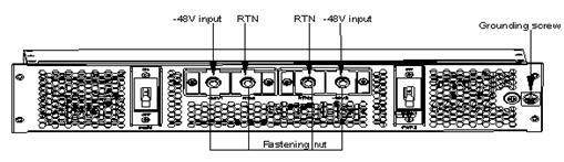
Figure 4-8 Connect the DC power cables of the S7506
4.6.3 Connecting PoE Power Cables
Follow these steps to connect the PoE power cables:
1) Loosen the nuts on the PoE terminal block cover and remove the cover.
2) Loosen the nuts of the PoE terminal block on the rear panel of the switch.

|
(1) NEG (-) terminal for connecting external PoE power supply |
(2) RTN (+) terminal for connecting external PoE power supply |
|
(3) COM port (for monitoring external PoE power supply) |
|
Figure 4-9 Rear panel of S7506 XGbus
3) Connect the –48V OT terminal of the PoE power cable marked with “–48V” to the NEG (-) terminal on the switch and fasten the nut. Connect the other end to the NEG (-) terminal on the panel of the external PoE power supply.

Figure 4-10 Rear panel of external PoE power supply (PSE2500-A3)
4) Connect the GND OT terminal of the PoE power cable marked with “GND“ to the RTN (+) terminal on the switch and fasten the nut. Connect the other end to the NEG (-) terminal on the panel of external PoE power supply.
5) Connect the PGND OT terminal of the PoE power cable marked with “PGND” to the grounding screw on the switch and fasten the screw. Connect the other end to the grounding strip for the switch.
& Note:
For the detailed installation procedure of PSE2500-A3, refer to the user manual shipped with PSE2500-A3.
4.7 Connecting Interface Cables
4.7.1 Connecting the Console Cable
I. Introduction
The console cable is an 8-core shielded cable. It has an RJ-45 connector at one end for the console port on the switch, and a DB-9 female connector at the other end for a 9-pin serial port on the configuration terminal. The following figure illustrates the console cable.
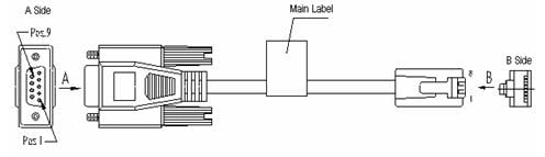
Table 4-1 Console cable pinout
|
RJ45 |
Signal |
DB-9 |
Signal |
|
1 |
RTS |
8 |
CTS |
|
2 |
DTR |
6 |
DSR |
|
3 |
TXD |
2 |
RXD |
|
4 |
SG |
5 |
SG |
|
5 |
SG |
5 |
SG |
|
6 |
RXD |
3 |
TXD |
|
7 |
DSR |
4 |
DTR |
|
8 |
CTS |
7 |
RTS |
II. Connection procedure
Follow these steps to connect the console cable to configure the switch through a terminal.
1) Connect the DB-9 female connector of the console cable to the serial port on the PC or the configuration terminal.
2) Connect the RJ-45 connector of the console cable to the console port on the switch.
& Note:
The RS-232 serial port is not hot swappable. You are recommended to disconnect the power supply to the PC or terminal before connecting the DB-9 connector. Or you can first connect the DB-9 connector and then insert the RJ-45 connector of the console cable into the console port.
4.7.2 Connecting the AUX Cable
The AUX cable is used for remote configuration of the S7500 series through Modem dial-up connection.
I. Introduction
The AUX cable is an 8-core shielded cable. It has an RS-232 RJ-45 connector at one end for the console port on the switch, and a DB-9 male connector at the other end for a 9-pin serial port on the Modem. The AUX cable is the same as the console cable. For details, see Figure 4-11 and Table 4-1.
II. Connection procedure
1) Connect the RJ-45 connector of the AUX cable to the console port on the switch.
2) Connect the DB-9 connector of the AUX cable to the serial port on the analog Modem.
4.7.3 Connecting the COM Port Cable
I. Introduction
The COM port cable is an 8-core shielded cable. It has an RJ-45 connector at one end for the COM port on the switch, and a DB-9 female connector for a 9-pin serial port on the configuration terminal. The COM port cable is the same as the console cable. For details, see Figure 4-11 and Table 4-1.
II. Connection procedure
When the S7500 switch connects with the external PoE power supply, the switch can monitor the running status of the external PoE power supply through the COM port. Take the following steps to connect the COM port cable:
1) Connect the DB-9 female connector of the COM port cable to the RS232 serial port on the external PoE power supply.
2) Connect the RJ-45 connector of the COM port cable to the COM port on the switch.
4.7.4 Connecting Category-5 Cables
I. Introduction to RJ-45 connector
10Base-T/100Base-TX and 1000Base-T ports of the S7500 series match RJ-45 connectors, support MDI/MDIX auto-sensing, and adopt category-5 cables. The following figure illustrates the appearance and pinouts of RJ-45 connector.

Table 4-2 RJ-45 MDI connector pinouts
|
Pinout |
10Base-T/100Base-TX |
1000Base-T |
||
|
Signal |
Function |
Signal |
Function |
|
|
1 |
Tx+ |
Transmit data |
BIDA+ |
Bi-directional data cable A+ |
|
2 |
Tx- |
Transmit data |
BIDA- |
Bi-directional data cable A- |
|
3 |
Rx+ |
Receive data |
BIDB+ |
Bi-directional data cable B+ |
|
4 |
Reserved |
— |
BIDC+ |
Bi-directional data cable C+ |
|
5 |
Reserved |
— |
BIDC- |
Bi-directional data cable C- |
|
6 |
Rx- |
Receive data |
BIDB- |
Bi-directional data cable B- |
|
7 |
Reserved |
— |
BIDD+ |
Bi-directional data cable D+ |
|
8 |
Reserved |
— |
BIDD- |
Bi-directional data cable D- |
& Note:
Tx = Transmit data
Rx = Receive data
BI = Bi-directional data
Table 4-3 RJ-45 MDI-X connector pinouts
|
Pinout |
10Base-T/100Base-TX |
1000Base-T |
||
|
Signal |
Function |
Signal |
Function |
|
|
1 |
Rx+ |
Receive data |
BIDB+ |
Bi-directional data cable B+ |
|
2 |
Rx- |
Receive data |
BIDB- |
Bi-directional data cable B- |
|
3 |
Tx+ |
Transmit data |
BIDA+ |
Bi-directional data cable A+ |
|
4 |
Reserved |
— |
BIDD+ |
Bi-directional data cable D+ |
|
5 |
Reserved |
— |
BIDD- |
Bi-directional data cable D- |
|
6 |
Tx- |
Transmit data |
BIDA- |
Bi-directional data cable A- |
|
7 |
Reserved |
— |
BIDC+ |
Bi-directional data cable C+ |
|
8 |
Reserved |
— |
BIDC- |
Bi-directional data cable C- |
& Note:
Pinouts 1 and 2 (negative), 3 and 6 (positive) are used for the external PoE power supply.
II. Connection procedure
Follow these steps to connect a category-5 cable:
1) Connect one end of the network cable to an RJ-45 Ethernet port on the switch.
2) Connect the other end of the cable into an RJ-45 port on the peer device.
4.7.5 Connecting Fibers
I. Introduction to fiber connector
Before connecting fibers, make sure the connector and the fiber are consistent with the optical port.
Fiber connectors are indispensable passive components in optical fiber communication systems. Fiber connectors make it possible that fibers can be removable. As a result, debugging and maintenance of the optical system become more convenient, and transfer dispatching more flexible. Among diversified fiber connectors, only SC and LC will be introduced here.
l SC fiber connector

l LC fiber connector

II. Connection procedure
Follow these steps to connect an optical fiber
1) Remove the protective cap from the fiber connector and clean the end-face surface of the fiber.
2) Remove the protective cap from the optical port on the switch, and connect one end of the fiber to the port.
3) Connect the other end of the fiber to the corresponding device.
![]() Caution:
Caution:
When an optical port is not connected with a fiber connector or its protective cap is open, there might be invisible radiation emitted from the port. So do not stare into the optical port directly.
Cover the optical port with a protection cap if there is no connector plugged in.
4.8 Cabling
4.8.1 Cabling for Desk-Mounting
If you mount the switch on a desktop, run all service cables on the cable management bracket on the left side of the chassis, and AC or DC power cables on the rear of chassis.
4.8.2 Cabling for Cabinet-Mounting
If you mount the switch in a standard 19-inch cabinet or N68 cabinet, bind all service cables to the cable management bracket on the left side of the cabinet. Run the service cables as you run the signal cables (on cabling racks or in raised floor) in the equipment room. Put all signal cables connectors at the bottom of the chassis, instead of outside of the chassis for fear of unexpected damage. From the left of the rear panel of the cabinet, run the power cables on cabling racks or in raised floor as near as possible according to the positions of the PDF, lightning protection box, and terminal strips in the equipment room.
4.9 Cable Binding
4.9.1 Correct Use of Labels
Correctly fill in labels and paste them to the right places on the cables before binding.
4.9.2 Precautions for Cable Binding
l Bind the cables straight in the cabinet, without any twisting or bending. See Figure 4-15

Figure 4-15 Cable binding example I
l Keep the cable bend radius at least twice the cable diameter, and at least five times at a connector.
l Run and bind different types of cables (power cables, signal cables, and grounding cable) separately in a cabinet. If they are very close to each other, lay them in a cross way. If you lay cables in a parallel way, keep the distance between power cables and signal cables at least 30 mm (1.2 in).
l Keep all binding brackets and cabling troughs smooth, without any sharp edges.
l Round metal holes which cables go through or furnish them with an insulating bush.
l Use the proper size cable ties, instead of combined ties, to bind cables. Currently, the following cable tie sizes are available: 100 × 2.5 mm (3.9 × 0.01 in), 150 × 3.6 mm (5.9 × 0.1 in), 300 × 3.6 mm (11.8 × 0.1 in), 530 × 9 mm (20.9 × 0.4 in), and 580 × 13 mm (22.8 × 0.5 in);
l Cut the extra parts of the cable ties neatly, without any sharp points. See Figure 4-16

Figure 4-16 Cable binding example II
l Before bending the cables, bind them first. But do not bind the cables at the bent area for fear of breaking cable cores due to excessive stress. See Figure 4-17.

Figure 4-17 Cable binding example III
l Fold and bind the spare cables or excessive parts to a proper position in the cabinet or cabling troughs so that they will not affect the operation of the switch, or damage the switch, or get damaged during system commissioning.
l Do not bind the 220V power cable or –48V power cables to the moving parts on the guide rails.
l Provide an extra length for the cables connecting moving parts (for example, the grounding cable connected to the cabinet door) to free the cables from possible stress. On the other hand, make sure the cables will not touch any heat source, or sharp points and edges when the moving part reaches its installation position. Use high temperature cables if heat sources exist nearby.
l Fasten the screws or nuts on the cable terminals stud and take measures to prevent them from getting loosened. See Figure 4-18.

l Fix hard cables in a place near to the cable terminal studs to free the terminal studs and cables from stress.
l Do not use self-tapping screw to fasten cabling terminal studs.
l Bind the same type of cables in the same direction together by reference to Table 4-4 and keep the cable bundle clean and straight.
Table 4-4 Recommendations on cable tie binding
|
Cable bundle diameter |
Spacing between cable ties |
|
10 mm (0.4 in.) |
80 mm to 150 mm (3.1 in. to 5.9 in.) |
|
10 mm to 30 mm (0.4 in. to 1.2 in.) |
150 mm to 200 mm (5.9 in. to 7.9 in.) |
|
30 mm (1.2 in.) |
200 mm to 300 mm (7.9 in. to 11.8 in.) |
l Do not knot any cable when running or tying cables.
l Do not expose the metal part of crimping cold-pressed terminal blocks (such as air switch).
4.10 Checking the Installation
![]() Caution:
Caution:
Before check, turn off the power supply to avoid bodily injury or device damage due to improper connection.
After the installation, check whether the items listed Table 4-5 are normal.
Table 4-5 Installation checklist
|
Item |
Normal |
Abnormal (Remarks) |
|
ESD-preventive wrist strap |
|
|
|
Console cable |
|
|
|
Grounding cable |
|
|
|
Power cable |
|
|
|
SRPU |
|
|
|
LPU |
|
|
|
Fan tray |
|
|