- Table of Contents
-
- H3C S3610[5510] Series Ethernet Switches Operation Manual-Release 0001-(V1.02)
- 00-1Cover
- 00-2Product Overview
- 01-Login Operation
- 02-VLAN Operation
- 03-IP Address and Performance Operation
- 04-QinQ-BPDU Tunnel Operation
- 05-Port Correlation Configuration Operation
- 06-MAC Address Table Management Operation
- 07-MAC-IP-Port Binding Operation
- 08-MSTP Operation
- 09-Routing Overview Operation
- 10-IPv4 Routing Operation
- 11-IPv6 Routing Operation
- 12-IPv6 Configuration Operation
- 13-Multicast Protocol Operation
- 14-802.1x-HABP-MAC Authentication Operation
- 15-AAA-RADIUS-HWTACACS Operation
- 16-ARP Operation
- 17-DHCP Operation
- 18-ACL Operation
- 19-QoS Operation
- 20-Port Mirroring Operation
- 21-Cluster Management Operation
- 22-UDP Helper Operation
- 23-SNMP-RMON Operation
- 24-NTP Operation
- 25-DNS Operation
- 26-File System Management Operation
- 27-Information Center Operation
- 28-System Maintenance and Debugging Operation
- 29-NQA Operation
- 30-VRRP Operation
- 31-SSH Operation
- 32-Appendix
- Related Documents
-
| Title | Size | Download |
|---|---|---|
| 28-System Maintenance and Debugging Operation | 2 MB |
Table of Contents
Chapter 1 Basic Configurations
1.1.2 Online Help with Command Lines
1.1.5 Command Line Error Information
1.2.1 Entering/Exiting System View
1.2.2 Switch CLI Language Mode
1.2.4 Configuring System Clock
1.2.5 Configuring Welcome Information
1.2.7 Configuring User Levels and Command Levels
1.2.8 Displaying System Configuration Information and Running Information
1.2.9 Displaying System Statistics
Chapter 2 System Maintaining and Debugging
2.1 System Maintaining and Debugging Overview
2.1.1 Introduction to System Maintaining and Debugging
2.1.2 Introduction to System Debugging
2.2 System Maintaining and Debugging
2.3 System Maintaining and Debugging Example
3.1 Device Management Overview
3.2 BootROM and Host Software Loading
3.2.1 Introduction to Loading Approaches
3.3 Device Management Configuration
3.3.2 Specifying a BootROM File for the Next Device Boot
3.3.3 Upgrading a BootROM File
3.3.4 Clearing the 16bit Interface Indexes Not Used in the Current System
3.4 Displaying and Maintaining Device Management Configuration
3.5 Remote Upgrade Configuration Example
Chapter 1 Basic Configurations
While configuring the system, go to these sections for information you are interested in:
1.1 CLI Features
This section covers the following topics:
l Online Help with Command Lines
l Command Line Error Information
1.1.1 CLI Overview
H3C S3610&S5510 Series Ethernet Switches provide a series of configuration commands and command line interface for you to configure and maintain the Ethernet switches. The command line interface is featured by the following:
l Configure the command levels to make sure that unauthorized users cannot use related commands to configure a switch.
l You can enter <?> at any time to get the online help.
l Provide network test commands, such as tracert, and ping, to help you to diagnose the network.
l Provide plenty of detail debugging information to help you to diagnose and locate the network failures.
l Provide a function similar to Doskey to execute a history command.
l Adopt the partial match method to search for the keywords of a command line. You only need to enter a non-conflicting keyword to execute the command correctly.
1.1.2 Online Help with Command Lines
The following are the types of online help available with the CLI:
l Full help
l Fuzzy help
To obtain the desired help information, you can:
1) Enter <?> in any view to access all the commands in this view and brief description about them as well.
User view commands:
backup Backup next startup-configuration file to TFTP server
boot-loader Set boot loader
bootrom Update/read/backup/restore bootrom
cd Change current directory
clock Specify the system clock
cluster Run cluster command
copy Copy from one file to another
debugging Enable system debugging functions
delete Delete a file
dir List files on a file system
display Show running system information
<omitted>
2) Enter a command and a <?> separated by a space. If <?> is at the position of a keyword, all the keywords are given with a brief description.
<Sysname> language-mode ?
chinese Chinese environment
english English environment
3) Enter a command and a <?> separated by a space. If <?> is at the position of a parameter, the description about these parameters is given.
<Sysname> system-view
[Sysname] interface Vlan-interface ?
<1-4094> VLAN interface
[Sysname] interface Vlan-interface 1 ?
<cr>
[Sysname] interface Vlan-interface 1
Where, <cr> indicates that there is no parameter at this position. The command is then repeated in the next command line and executed if <Enter> is input.
<Sysname> pi?
ping
5) Enter a command followed by a character string and <?>. All the keywords starting with this string are listed.
<Sysname> display ver?
version
6) Press <tab> after entering the first several letters of a keyword to display the complete keyword, provided these letters can uniquely identify the keyword in this command.
7) You can view the help information in Chinese with the language-mode command.
1.1.3 Display Features
CLI offers the following features:
l It offers both English and Chinese help information. You can toggle between them.
l When the information displayed exceeds one screen, you can pause using one of the methods shown in Table 1-1
|
Action |
Function |
|
Enter <Space> when information display pauses |
Continues to display information of the next screen page |
|
Enter <Enter> when information display pauses |
Continues to display information of the next line. |
|
Enter <Ctrl+C> when information display pauses |
Stops the display and the command execution. |
1.1.4 History Command
The CLI can automatically save the commands that have been entered. You can invoke and repeatedly execute them whenever needed. By default, the CLI can save up to ten commands for each user. But you can configure the history command buffer size of the current user interface by using the history-command max-size command. For details about the command, refer to the Login module.
Table 1-2 lists the operation that you can perform.
Table 1-2 Access history commands
|
To do… |
Use the Key/command… |
Result |
|
View the history commands |
display history-command |
Displays the commands that you have entered |
|
Access the last history command |
Up-arrow key or <Ctrl+P> |
Displays the earlier history command, if there is any. Otherwise, the system rings alarm. |
|
Access the next history command |
Down-arrow key or <Ctrl+N> |
Displays the next history command, if there is any. Otherwise, the system clears the commands and rings alarm. |
& Note:
You may use arrow keys to access history commands in Windows 2000/XP Terminal or Telnet. However, the up-arrow and down-arrow keys are invalid in Windows 9X HyperTerminal, because they are defined in a different way. You can use <Ctrl+P> and <Ctrl+N> instead.
1.1.5 Command Line Error Information
The commands are executed only if they have no syntax error. Otherwise, error information is reported. Table 1-3 lists some common errors.
Table 1-3 Common command line errors
|
Error information |
Cause |
|
Unrecognized command |
The command was not found. |
|
The keyword was not found. |
|
|
Parameter type error |
|
|
The parameter value is beyond the allowed range. |
|
|
Incomplete command |
Incomplete command |
|
Too many parameters |
Too many parameters are input. |
|
Ambiguous command |
Parameter value input is ambiguous. |
|
Wrong parameter |
Wrong parameter |
1.1.6 Edit Features
The CLI provides the basic command edit functions and supports multi-line editing. The maximum length of each command is 256 characters. Table 1-4 lists these functions.
|
Key |
Function |
|
Common Keys |
If the editing buffer is not full, insert the character at the position of the cursor and move the cursor to the right. Otherwise, the alarm rings. |
|
Backspace key |
Delete the character to the left of the cursor and move the cursor back one character. If the cursor gets to the beginning of the command line, the alarm rings. |
|
Left-arrow key or <Ctrl+B> |
The cursor moves one character space to the left, and the alarm rings when the cursor gets to the beginning of the command line. |
|
Right-arrow key or <Ctrl+F> |
The cursor moves one character space to the right, and the alarm rings when the cursor gets to end of the command line. |
|
Up-arrow key or <Ctrl+P> |
Display history command |
|
Down-arrow key or <Ctrl+N> |
|
|
Tab key |
Pressing <Tab> after entering part of a keyword enables the fuzzy help function. If finding a unique match, the system will substitute the complete keyword for the incomplete one and display it in the next line. If there are several matches or no match at all, the system will not modify the incomplete keyword and display it again in the next line. |
1.1.7 CLI Views
CLI views are designed for different configuration tasks. They are interrelated. You will enter user view once you log into a switch successfully, where you can perform operations such as displaying operation status and statistical information. And by executing the system-view command, you can enter system view, where you can enter other views by executing the corresponding commands.
The following CLI views are provided:
l User view
l System view
l Ethernet port view
l NULL interface view
l VLAN view
l VLAN interface view
l Loopback interface view
l Tunnel interface view
l Local user view
l User interface view
l FTP client view
l MST region view
l IGMP-Snooping view
l MLD-Snooping view
l Traffic classifier view
l Traffic behavior view
l QoS policy view
l Cluster view
l Port group view
l NQA view
l HWTACACS scheme view
l Public key view
l Public key editing view
l Routing policy view
l Basic IPv4 ACL view
l Advanced IPv4 ACL view
l Ethernet frame header ACL view
l User-defined ACL view
l Basic IPv6 ACL view
l Advanced IPv6 ACL view
l QinQ view
l RADIUS scheme view
l RIP view
l RIPng view
l ISP domain view
l <omitted>
Table 1-5 lists information about CLI views (including the operations you can performed in these views, how to enter these views, and so on).
|
View |
Available operation |
Prompt example |
Enter method |
Quit method |
|
User view |
Display operation status and statistical information |
<Sysname> |
Enter user view once logging into the switch. |
Execute the quit command in user view to log out of the switch. |
|
System view |
Configure system parameters |
[Sysname] |
Execute the system-view command in user view. |
Execute the quit or return command to return to user view. |
|
Ethernet port view |
Configure Ethernet port parameters |
[Sysname- Ethernet1/0/1] |
Ethernet port view Execute the interface Ethernet 1/1/1 command in system view. |
Execute the quit command to return to system view. Execute the return command to return to user view. |
|
[Sysname- GigabitEthernet1/0/1] |
Gigabit Ethernet port view Execute the interface GigabitEthernet 1/1/1 command in system view. |
|||
|
NULL interface view |
Configure NULL interface parameters |
[Sysname- NULL0] |
Execute the interface null 0 command in system view |
Execute the quit command to return to system view. Execute the return command to return to user view. |
|
VLAN view |
Configure VLAN parameters |
[Sysname-vlan1] |
Execute the vlan 1 command in system view. |
Execute the quit command to return to system view. Execute the return command to return to user view. |
|
VLAN interface view |
Configure IP interface parameters for VLANs and aggregated VLANs |
[Sysname-Vlan- interface1] |
Execute the interface Vlan-interface 1 command in system view. |
Execute the quit command to return to system view. Execute the return command to return to user view. |
|
Loopback interface view |
Configure Loopback interface parameters |
[Sysname- LoopBack0] |
Execute the interface Loopback 0 command in system view |
Execute the quit command to return to system view. Execute the return command to return to user view. |
|
Tunnel interface view |
Configure Tunnel interface parameters |
[Sysname- Tunnel0] |
Execute the interface Tunnel 0 command in system view. |
Execute the quit command to return to system view. Execute the return command to return to user view. |
|
Local user view |
Configure local user parameters |
[Sysname-luser-user1] |
Execute the local-user user1 command in system view. |
Execute the quit command to return to system view. Execute the return command to return to user view. |
|
User interface view |
Configure user interface parameters |
[Sysname-ui0] |
Execute the user-interface 0 command in system view. |
Execute the quit command to return to system view. Execute the return command to return to user view. |
|
FTP client view |
Configure FTP client parameters |
[ftp] |
Execute the ftp command in user view. |
Execute the quit command to return to user view. |
|
MST region view |
Configure MST region parameters |
[Sysname-mst- region] |
Execute the stp region-configuration command in system view. |
Execute the quit command to return to system view. Execute the return command to return to user view. |
|
IGMP- Snooping view |
Configure IGMP– Snooping protocol parameters |
[Sysname-igmp-snooping] |
Execute the igmp-snooping command in system view. |
Execute the quit command to return to system view. Execute the return command to return to user view. |
|
MLD- Snooping view |
Configure MLD-Snooping protocol parameters |
[Sysname-mld- snooping] |
Execute the mld-snooping command in system view. |
Execute the quit command to return to system view. Execute the return command to return to user view. |
|
Traffic classifier view |
Configure traffic classifier related parameters |
[Sysname- classifier-test] |
Execute the traffic classifier test command in system view. |
Execute the quit command to return to system view. Execute the return command to return to user view. |
|
Traffic behavior view |
Configure traffic behavior related parameters |
[Sysname- behavior-test] |
Execute the traffic behavior test command in system view |
Execute the quit command to return to system view. Execute the return command to return to user view. |
|
QoS policy view |
Configure QoS policy related parameters |
[Sysname- qospolicy-test] |
Execute the qos policy test command in system view |
Execute the quit command to return to system view. Execute the return command to return to user view. |
|
Cluster view |
Configure cluster parameters |
[Sysname- cluster] |
Execute the cluster command in system view. |
Execute the quit command to return to system view. Execute the return command to return to user view. |
|
Port group view |
Configure manual port group parameters |
[Sysname-port- group-manual- test] |
Execute the port-group manual test command in system |
Execute the quit command to return to system view. Execute the return command to return to user view. |
|
Configure aggregate port group parameters |
[Sysname-port-group- aggregation-1] |
Execute the port-group aggregation 1 command in system view |
||
|
NQA view |
Configure NQA parameters |
[Sysname-nqa- admin-test] |
Execute the nqa admin test command in system view |
Execute the quit command to return to system view. Execute the return command to return to user view. |
|
HWTACACS scheme view |
Configure HWTACACS parameters |
[Sysname- hwtacacs-test] |
Execute the hwtacacs scheme test command in system view |
Execute the quit command to return to system view. Execute the return command to return to user view. |
|
Public key view |
Configure RSA public keys for SSH users |
[Sysname-rsa- public-key] |
Execute the rsa peer-public-key h3c003 command in system view. |
Execute the peer-public-key end command to return to system view. |
|
Public key editing view |
Edit RSA public keys of SSH users |
[Sysname-rsa- key-code] |
Execute the public-key-code begin command in public key view. |
Execute the public-key-code end command to return to public key view. |
|
Routing policy view |
Configure routing policies |
[Sysname-route-policy] |
Execute the route-policy policy1 permit node 10 command in system view |
Execute the quit command to return to system view. Execute the return command to return to user view. |
|
Basic IPv4 ACL view |
Define rules for a basic IPv4 ACL (ACLs with their IDs ranging from 2000 to 2999 are basic ACLs.) |
[Sysname-acl- basic-2000] |
Execute the acl number 2000 command in system view. |
Execute the quit command to return to system view. Execute the return command to return to user view. |
|
Advanced IPv4 ACL view |
Define rules for an advanced IPv4 ACL (ACLs with their IDs ranging from 3000 to 3999 are advanced ACLs.) |
[Sysname-acl- adv-3000] |
Execute the acl number 3000 command in system view. |
Execute the quit command to return to system view. Execute the return command to return to user view. |
|
Ethernet frame header ACL view |
Define the sub-rules of Ethernet frame header ACLs, which is numbered from 4000 to 4999. |
[Sysname-acl- ethernetframe- 4000] |
Execute the acl number 4000 command in system view. |
Execute the quit command to return to system view. Execute the return command to return to user view. |
|
User- defined IPv4 ACL view |
Define the sub-rules of user-defined IPv4 ACLs, which are in the range of 5000 to 5999 |
[Sysname-acl- user-5000] |
Execute the acl number 5000 command in system view |
Execute the quit command to return to system view. Execute the return command to return to user view. |
|
Basic IPv6 ACL view |
Define rules for a basic IPv6 ACL (ACLs with their IDs ranging from 2000 to 2999 are basic ACLs.) |
[Sysname-acl6-basic-2000] |
Execute the acl ipv6 number 2000 command in system view. |
Execute the quit command to return to system view. Execute the return command to return to user view. |
|
Advanced IPv6 ACL view |
Define rules for an advanced IPv6 ACL (ACLs with their IDs ranging from 3000 to 3999 are advanced ACLs.) |
[Sysname-acl6-adv-3000] |
Execute the acl ipv6 number 3000 command in system view. |
Execute the quit command to return to system view. Execute the return command to return to user view. |
|
QinQ view |
Create a QinQ instance and configure QinQ related parameters. |
[Sysname- Ethernet1/0/1- vid-1] |
Execute the vlan-vpn vid 1 command in Ethernet view |
Execute the quit command to return to system view. Execute the return command to return to user view. |
|
[Sysname- GigabitEthernet1/1/1-vid-1] |
||||
|
RADIUS scheme view |
Configure RADIUS parameters |
[Sysname- radius-1] |
Execute the radius scheme 1 command in system view. |
Execute the quit command to return to system view. Execute the return command to return to user view. |
|
RIP view |
Configure RIP parameters |
[Sysname-rip-1] |
Execute the rip 1 command in system view |
Execute the quit command to return to system view. Execute the return command to return to user view. |
|
RIPng view |
Configure RIPng parameters |
[Sysname-ripng-1] |
Execute the ripng 1 command in system view |
Execute the quit command to return to system view. Execute the return command to return to user view. |
|
ISP domain view |
Configure parameters for an ISP domain |
[Sysname-isp- aabbcc.net] |
Execute the domain aabbcc.net command in system view. |
Execute the quit command to return to system view. Execute the return command to return to user view. |
1.2 Basic Configurations
This section covers the following topics:
l Entering/Exiting System View
l Configuring Welcome Information
l Configuring User Levels and Command Levels
l Displaying System Configuration Information and Running Information
l Displaying System Statistics
1.2.1 Entering/Exiting System View
You will enter user view automatically after you log into the device. And a prompt <Sysname> will be displayed on the screen.
Table 1-6 Follow these steps to enter/exit system view
|
To do… |
Use the command… |
Remarks |
|
Enter system view from user view |
system-view |
You enter user view automatically after logging onto the device. |
|
Return to user view from system view |
quit |
— |
& Note:
With the quit command, you can return to the previous view or exit the system from user view. The hot key <Ctrl+Z> is equivalent to the return command.
1.2.2 Switch CLI Language Mode
The device supports two CLI language modes, English and Chinese. You can switch the CLI language mode as needed.
Table 1-7 Follow these steps to switch CLI language mode
|
To do… |
Use the command… |
Remarks |
|
Switch CLI language mode |
language-mode { chinese | english } |
Optional CLI language is English by default. |
1.2.3 Configuring Device Name
You can use the sysname command to set the device name. The set device name is correlated to the CLI prompt. For example, if the device name is set to Sysname, the prompt in user view will be <Sysname>.
Table 1-8 Follow these steps to configure the device name
|
To do… |
Use the command… |
Remarks |
|
Enter system view |
system-view |
— |
|
Configure the device name |
sysname sysname |
Optional By default, the device name is H3C. |
1.2.4 Configuring System Clock
To ensure that the device works with other devices properly, you need to set a correct system clock.
Table 1-9 Follow these steps to configure the system clock
|
To do… |
Use the command… |
Remarks |
|
Set the standard time |
clock datetime time date |
Optional |
|
Set the time zone |
clock timezone time-zone-name { add | minus } time |
Optional |
|
Set a daylight summer time scheme |
clock summer-time zone_name one-off start-time start-date end-time end-date add-time |
Optional |
|
clock summer-time zone-name repeating { start-time start-date end-time end-date | start-time start-year start-month start-week start-day end-time end-year end-month end-week end-day } offset-time |
1.2.5 Configuring Welcome Information
I. Introduction to welcome information
Welcome information is a piece of prompt displayed when a user connects to a device for logging and interoperation. The administrator is allowed to configure the banner as the situation requires.
For the time being, there are five kinds of banners available:
l Shell welcome information or session banner, displayed when you enter console session.
l User interface welcome information or incoming banner, displayed when a user interface is enabled by TTY Modem.
l Logging welcome information or login banner, displayed when the user configures password authentication and scheme authentication,
l MOTD welcome information, displayed before the authentication is started.
l Authorization welcome information or legal banner. When a user logins into a device, the system displays some copyright or authorization information and a legal banner and waits for confirmation of the user. If the user enters “Y” or the <Enter> key, the authentication or login process continues; if the user enters “N”, the authentication or login process breaks. "Y” and “N” are case-insensitive.
II. Configuring welcome information
There are two modes to configure welcome information:
The first mode is to enter all the welcome content right after the command keywords in one line. The beginning character and the end character of the entered content must be the same, but the two characters are not part of the welcome information. In this case, the command keywords, the beginning and end characters, and the welcome information altogether must not exceed 510 characters. The second mode is to enter the welcome content in two or more lines, each line ended with an <Enter> key. In this case, the content may be up to 2000 characters.
You can enter contents in multiple lines in three ways:
l Straight <Enter> in the first line: End the configuration with “%”. The <Enter> and “%” characters are not included in the banner content.
l One character followed with <Enter> in the first line: End the configuration with the character entered in the first line. The character entered in the first line and the ending character are not included in the banner content.
l Multiple characters (the leading and ending characters are different) followed with <Enter> in the first line: End the configuration with the first character of the first line. The first character of the first line and the ending character are not included in the banner content.
Table 1-10 Follow these steps to configure welcome information
|
To do… |
Use the command… |
Remarks |
|
Enter system view |
system-view |
— |
|
Configure the welcome information at entering user view (TTY Modem login mode) |
header incoming [ text ] |
Optional |
|
Configure the welcome information at login authentication |
header login [ text ] |
Optional |
|
Configure the authorization information before logging onto the terminal |
header legal [ text ] |
Optional |
|
Configure the welcome information at entering user view (non-TTY Modem login mode) |
header shell [ text ] |
Optional |
|
Configure the welcome information before logging onto the terminal |
header motd [ text ] |
Optional |
1.2.6 Configuring CLI Hotkeys
Table 1-11 Follow these steps to configure CLI hotkeys
|
To do… |
Use the command… |
Remarks |
|
Enter system view |
system-view |
— |
|
Configure CLI hotkeys |
hotkey [ CTRL_G | CTRL_L | CTRL_O | CTRL_T | CTRL_U ] command |
Optional Refer to the note below this table for the default case. |
|
Display hotkeys |
display hotkey |
Available in any view. Refer to Table 1-12 for hotkeys reserved by system. |
& Note:
By default, the <Ctrl+G>, <Ctrl+L> and <Ctrl+O> hotkeys are associated with command lines as follows and the <Ctrl+T> and <Ctrl+U> commands are NULL.
l <Ctrl+G> corresponds to the display current-configuration command.
l <Ctrl+L> corresponds to the display ip routing-table command.
l <Ctrl+O> corresponds to the undo debugging all command.
Table 1-12 Hotkeys reserved by the system
|
Hotkey |
Function |
|
<Ctrl+A> |
Move the cursor to the beginning of the current line. |
|
<Ctrl+B> |
Move the cursor one character to the left. |
|
<Ctrl+C> |
Stop performing a command. |
|
<Ctrl+D> |
Delete a character. |
|
<Ctrl+E> |
Move the cursor to the end of the current line. |
|
<Ctrl+F> |
Move the cursor one character to the right. |
|
<Ctrl+H> |
Delete the character to the left of the cursor. |
|
<Ctrl+K> |
Break an outward connection. |
|
<Ctrl+N> |
Display the next command after history command buffer. |
|
<Ctrl+P> |
Display the next command before history command buffer. |
|
<Ctrl+R> |
Redisplay the current line information. |
|
<Ctrl+V> |
Paste the content in the clipboard. |
|
<Ctrl+W> |
Delete all the characters in a continuous string to the left of the cursor. |
|
<Ctrl+X> |
Delete all the characters to the left of the cursor. |
|
<Ctrl+Y> |
Delete all the characters to the right of the cursor. |
|
<Ctrl+Z> |
Return to user view. |
|
<Ctrl+]> |
Break an inward connection or redirect connection. |
|
<Esc+B> |
Move the cursor to the leading character of the continuous string to the left. |
|
<Esc+D> |
Delete all the characters of the continuous string to the left of the cursor. |
|
<Esc+F> |
Move the cursor to the front of the next continuous string to the right. |
|
<Esc+N> |
Move the cursor down by one line (available before press the Enter key) |
|
<Esc+P> |
Move the cursor up by one line (available before press the Enter key) |
|
<Esc+<> |
Specify the cursor as the beginning of the clipboard. |
|
<Esc+>> |
Specify the cursor as the ending of the clipboard. |
& Note:
These hotkeys are defined by the system. When a user interacts with the device from terminal software, they may be defined to perform other operations. If so, the definition of the terminal software will dominate.
1.2.7 Configuring User Levels and Command Levels
Corresponding to the command levels, the system categorizes users into 4 levels. A user can perform only the commands that have the command levels equal to or below the user level.
The command levels include visit, monitor, system and management, as the following:
l Visit: Used for network diagnosing commands (ping, tracert), commands sent to outer devices (including Telnet client, SSH client, RLOGIN), etc. Commands of this level cannot save configuration files.
l Monitor: Used for system maintaining, service troubleshooting, etc, including commands such as refresh, reset and send. Commands of this level cannot save configuration files.
l System: Used for service configuration, including commands of routing and different network layers. Commands of this level provide users with direct network services.
l Management: Used for commands related to system running and system support modules, including file system, FTP, TFTP, Xmodem download, configuration file switching, power control, backup board control, user management, level configuration and interim system parameter configuration (non-protocol and non-RFC).
You need to enhance your user level to obtain privileges to use commands of higher levels. When switching the user level, you are required to enter the corresponding password for the sake of security. The password entered is not displayed on the screen. If it is entered correctly within three times, the user level is switched to a higher level.
You can specify the command level and its view as required. Every command has its own default view and privilege and you don’t have to re-configure it.
Table 1-13 Default command levels
|
Level |
Privilege |
Command |
|
0 |
Visit |
ping, tracert, telnet |
|
1 |
Monitor |
display, debugging |
|
2 |
System |
All configuration commands except for those at manage level |
|
3 |
Manage |
FTP, TFTP, Xmodem, and file system operation commands |
Table 1-14 Follow these steps to configure user level and command level
|
To do… |
Use the command… |
Remarks |
|
Switch the user level |
super [ level ] |
Optional |
|
Enter system view |
system-view |
— |
|
Configure the password to switch the user level |
super password [ level user-level ] { simple | cipher } password |
Optional |
|
Configure the command level in system view |
command-privilege level level view view command |
Optional |
& Note:
l The commands available depend on the user level when the user login a device. For example, if the user level is 3 and the command level of VTY 0 interface is 1, the user can user command below level 3 (inclusive).
l When configuring the password for switching user level with the super password command, the user level is defaulted to 3 if no user level is specified.
l Cipher passwords are recommended, as simple ones are easy getting stolen.
l Users can switch to a lower user level unconditionally. To switch to a higher user level, however, they need to enter the password needed (The password can be set with the super password command.). If the entered password is incorrect or no password is configured, the switch fails. Therefore, before switching to a higher user level, users should configure the password needed.
1.2.8 Displaying System Configuration Information and Running Information
After the above configuration, you can execute the display command in any view to display the corresponding configuration and operation information of the system.
Table 1-15 Follow these steps to display system status information
|
To do… |
Use the command… |
Remarks |
|
Display information on system version |
display version |
Available in any view |
|
Display information on the system clock |
display clock |
|
|
Display information on terminal users |
display users [ all ] |
|
|
Display the current configuration |
display current-configuration [ interface interface-type [ interface-number ] | configuration [ configuration-type ] ] | [ by-linenum ] | [ | { begin | include | exclude } text ] ] |
|
|
Display the valid configuration under current view |
display this [ by-linenum ] |
|
|
Display clipboard information |
display clipboard |
l The above is just an introduction of the global display command. For the display command related to different protocols and interfaces, refer to the corresponding sections.
l The display saved-configuration command displays no information if the device starts no configuration file when starting up, namely, the current startup file displayed with the display startup command is null. If you have saved configuration after starting up the device, the configuration file save the last time is displayed. For detailed information of the display saved-configuration command, see the File System Management part.
1.2.9 Displaying System Statistics
When the device is faulty, you may need to view operating information to locate the problem. As each functional module has its own operating information display command, you need to execute these commands one by one to view the information of all modules. To collect more information at a time, you can execute the display diagnostic-information command in any view to display the statistics information of each module of the system.
Table 1-16 Follow these steps to display system statistics
|
To do… |
Use the command… |
Remarks |
|
Display statistics of each module’s running status in the system |
display diagnostic-information |
— |
Use the display diagnostic-information command to collect at one time the information displayed by each of the following commands:
l display version
l display device
l display current-configuration
l display saved-configuration
l display interface
l display memory
l display logbuffer
l display history-command
l display ipv6 statistics
l display mac-address
l display link-aggregation summary
l display stp brief
l display arp all
l display ip interface
l display ip statistics
l display fib
l display ip routing-table
l display multicast forwarding-table
l <omitted>
Chapter 2 System Maintaining and Debugging
When maintaining and debugging the system, go to these sections for information you are interested in:
l System Maintaining and Debugging Overview
l System Maintaining and Debugging
l System Maintaining and Debugging Example
2.1 System Maintaining and Debugging Overview
2.1.1 Introduction to System Maintaining and Debugging
You can use the ping command and the tracert command to verify the current network connectivity.
I. The ping command
Users can use the ping command to verify whether a device with a specified address is reachable, and to examine the network connectivity.
Take the following steps when using the ping command:
1) The source device sends ICMP ECHO-REQUEST packets to the destination device.
2) If the network is functioning properly, the destination device will respond by sending the source device ICMP ECHO-REPLY packets after receiving the ICMP ECHO-REQUEST packets.
3) If there is network failure, the source device will display information indicating that the address is unreachable.
4) Display the relative statistics after execution of the ping command.
Output of the ping command includes:
l Information on how the destination device responds towards each ICMP ECHO-REQUEST packet: if the source device has received the ICMP ECHO-REPLY packet within the time-out timer, it will display the number of bytes of the ECHO-REPLY packet, the packet sequence number, Time To Live (TTL), and the response time.
l If within the period set by the time-out timer, the destination device has not received the response packets, it will display the “Request time out.” information.
l The ping command applies to the name and IP address of a destination device, if the device name is unknown, the “Error: Ping: Unknown host host-name” information will be displayed.
l The statistics from execution of the command, which include number of sent packets, number of received ECHO-REPLY packets, percentage of packets that were not received, the minimum, average, and maximum response time.
II. The tracert command
Users can use the tracert command to trace the routers used while forwarding packets from the source to the destination device. In the event of network failure, users can identify the failed node(s) in this way.
Take the following steps when using the tracert command:
1) The source device sends a packet with a TTL value of 1 to the destination device.
2) The first hop (the router that has received the packet first) responds by sending a TTL-expired ICMP message with its IP address encapsulated to the source. In this way, the source device can get the address of the first router.
3) The source device sends a packet with a TTL value of 2 to the destination device.
4) The second hop responds with a TTL-expired ICMP message, which gives the source device the address of the second router.
5) The above process continues until the ultimate destination device is reached. In this way, the source device can trace the addresses of all the routers that have been used to get to the destination device.
2.1.2 Introduction to System Debugging
For the majority of protocols and new features provided, the system generally provides the related debugging functions to enable users to diagnose errors.
The following two functions control the debugging information display.
l Protocol debugging switch, which controls protocol specific debugging information
l Screen output function, which controls whether the debugging information is output on a certain screen
Figure 2-1 illustrates the relationship between the protocol debugging switch and the screen output switch. Only when both are turned on can debugging information be output on a terminal.

Figure 2-1 The relationship between the protocol and screen debugging switch
2.2 System Maintaining and Debugging
2.2.1 System Maintaining
Table 2-1 Follow these steps to maintain the system
|
To do… |
Use the command… |
Remarks |
|
Check whether a specified IP address can be reached |
ping [ ip ] [ -a source-ip | -c count | -f | -h ttl | -i interface-type interface-number | -m interval | -n | -p pad | -q | -r | -s packet-size | -t timeout | -tos tos | -v] * { ip-address | hostname } |
Available in any view |
|
Display the route between the current device and the destination device. |
tracert [ -a source-ip | -f first-ttl | -m max-ttl | -p port | -q packet-number | -w timeout ] * { ip-address | hostname } |
& Note:
l For a low-speed network, it is recommended that users set a larger value for the time-out timer (indicated by the -t parameter in the command) when configuring the ping command.
l If you specify the packet sending interface by providing the -i keyword when configuring the ping command, you can ping only the addresses in a directly connected network segment.
2.2.2 System Debugging
Table 2-2 Follow these steps to debug the system
|
To do… |
Use the command… |
Remarks |
|
Enable debugging for a specified module |
debugging { all [ timeout time ] | module-name [ option ] } |
Available in user view. |
|
Enable the terminal debugging |
terminal debugging |
|
|
Display the enabled debugging function |
display debugging [ interface interface-type interface-number ] [ module-name ] |
Available in any view |
& Note:
l The debugging commands are normally used when the administrator is diagnosing network failure.
l Output of the debugging information may reduce system efficiency, especially during execution of the debugging all command.
l After the debugging is completed, users may use the undo debugging all command to disable all the debugging functions simultaneously.
l The debugging information can be displayed on the terminal only when the debugging command and the terminal debugging command are both executed successfully.
2.3 System Maintaining and Debugging Example
I. Network requirements
l The IP address of the destination device is 10.1.1.4.
l Display the routers used while forwarding packets from the current device to the destination device.
II. Network diagram (omitted here)
III. Configuration Procedure
<Sysname> tracert 10.1.1.4
traceroute to 10.1.1.4 (10.1.1.4) 30 hops max, 40 bytes packet, press CTRL_C to break
1 128.3.112.1 19 ms 19 ms 0 ms
2 128.32.216.1 39 ms 39 ms 19 ms
3 128.32.136.23 39 ms 40 ms 39 ms
4 128.32.168.22 39 ms 39 ms 39 ms
5 128.32.197.4 40 ms 59 ms 59 ms
6 131.119.2.5 59 ms 59 ms 59 ms
7 129.140.70.13 99 ms 99 ms 80 ms
8 129.140.71.6 139 ms 239 ms 319 ms
9 129.140.81.7 220 ms 199 ms 199 ms
10 10.1.1.4 239 ms 239 ms 239 ms
The above output shows that nine routers are used from the source to the destination device.
Chapter 3 Device Management
& Note:
You can express the path to and the names of the BootROM upgrade file, boot application, and configuration file in the Flash in the following formats:
l "Path + file name": That is, the full file name is used to indicate a file under the specified path. A full file name can contain up to 63 characters.
l "File name": That is, only the file name, without path name, is used to indicate a file under the current working path. A file name can contain up to 56 characters.
l BootROM upgrade file, boot file, and configuration file can be stored under the root directory flash:/ only.
When configuring device management, go to these sections for information you are interested in:
l BootROM and Host Software Loading
l Device Management Configuration
l Displaying and Maintaining Device Management Configuration
l Remote Upgrade Configuration Example
3.1 Device Management Overview
Through the device management function, you can view the current working state of devices, configure operation parameters, and perform daily device maintenance and management.
Currently, the following device management functions are available:
l Rebooting a device
l Specifying a scheduled device reboot.
l Specifying a BootROM file for the next device reboot
l Upgrading a BootROM file.
3.2 BootROM and Host Software Loading
Traditionally, the loading of switch software is accomplished through a serial port. This approach is slow, inconvenient, and cannot be used for remote loading. To resolve these problems, the TFTP and FTP modules are introduced into the switch. With these modules, you can load/download software/files conveniently to the switch through an Ethernet port.
This chapter introduces how to load BootROM and host software to a switch locally and how to do this remotely.
3.2.1 Introduction to Loading Approaches
I. You can load software locally by using:
l XMODEM through Console port
l TFTP through Ethernet port
l FTP through Ethernet port
II. You can load software remotely by using:
l FTP
l TFTP
& Note:
The BootROM software version should be compatible with the host software version when you load the BootROM and host software.
3.2.2 Local Software Loading
If your terminal is directly connected to the switch, you can load the BootROM and host software locally.
Before loading the software, make sure that your terminal is correctly connected to the switch to insure successful loading.
& Note:
The loading process of the BootROM software is the same as that of the host software, except that during the former process, you should press <Ctrl+U> and <Enter> after entering the Boot Menu and the system gives different prompts. The following text mainly describes the BootROM loading process.
I. Boot Menu
Starting......
*************************************************************
* *
* H3C S3610-52P BOOTROM, Version 123 *
* *
*************************************************************
Copyright(c) 2004-2006 Hangzhou H3C Technologies Co., Ltd.
Creation date: Aug 3 2006, 11:57:55
CPU Clock Speed : 200MHz
BUS Clock Speed : 33MHz
Memory Size : 128MB
Mac Address : 0016e0bee200
Press Ctrl-B to enter Boot Menu...
Press <Ctrl+B>. The system displays:
Password :
& Note:
To enter the Boot Menu, you should press <Ctrl+B> within five seconds after the information “Press Ctrl-B to enter Boot Menu...” appears. Otherwise, the system starts to decompress the program; and if you want to enter the Boot Menu at this time, you will have to restart the switch.
Input the correct BootROM password (no password is need by default). The system enters the Boot Menu:
BOOT MENU
1. Download application file to flash
2. Select application file to boot
3. Display all files in flash
4. Delete file from flash
5. Modify bootrom password
6. Enter bootrom upgrade menu
7. Skip current configuration file
8. Set bootrom password recovery
9. Set switch startup mode
0. Reboot
Enter your choice(0-9):
II. Loading Software Using XMODEM through Console Port
XMODEM is a file transfer protocol that is widely used due to its simplicity and good performance. XMODEM transfers files via Console port. It supports two types of data packets (128 bytes and 1 KB), two check methods (checksum and CRC), and multiple attempts of error packet retransmission (generally the maximum number of retransmission attempts is ten).
The XMODEM transmission procedure is completed by a receiving program and a sending program: The receiving program sends negotiation characters to negotiate a packet checking method. After the negotiation, the sending program starts to transmit data packets. When receiving a complete packet, the receiving program checks the packet using the agreed method. If the check succeeds, the receiving program sends an acknowledgement character and the sending program proceeds to send another packet; otherwise, the receiving program sends a negative acknowledgement character and the sending program retransmits the packet.
1) Loading BootROM software
Follow these steps to load the BootROM software:
Step 1: At the prompt "Enter your choice(0-9):" in the Boot Menu, press <6> or <Ctrl+U>, and then press <Enter> to enter the BootROM update menu shown below:
Bootrom update menu:
1. Set TFTP protocol parameter
2. Set FTP protocol parameter
3. Set XMODEM protocol parameter
0. Return to boot menu
Enter your choice(0-3):
Step 2: Enter 3 in the above menu to download the BootROM software using XMODEM. The system displays the following download baud rate setting menu:
Please select your download baudrate:
1.* 9600
2. 19200
3. 38400
4. 57600
5. 115200
0. Return
Enter your choice (0-5):
Step 3: Choose an appropriate download baud rate. For example, if you enter 5, the baud rate 115200 bps is chosen and the system displays the following information:
Download baudrate is 115200 bps
Please change the terminal's baudrate to 115200 bps and select XMODEM protocol
Press enter key when ready
& Note:
If you have chosen 9600 bps as the download baud rate, you need not modify the HyperTerminal’s baud rate, and therefore you can skip Step 4 and 5 below and proceed to Step 6 directly. In this case, the system will not display the above information.
Following are configurations on PC. Take the Hyperterminal using Windows operating system as example.
Step 4: Choose [File/Properties] in HyperTerminal, click <Configure> in the pop-up dialog box, and then select the baud rate of 115200 bps in the Console port configuration dialog box that appears, as shown in Figure 3-1, Figure 3-2.
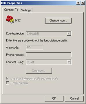
Figure 3-1 Properties dialog box
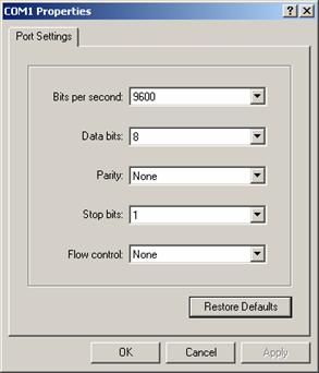
Figure 3-2 Console port configuration dialog box
Step 5: Click the <Disconnect> button to disconnect the HyperTerminal from the switch and then click the <Connect> button to reconnect the HyperTerminal to the switch, as shown in Figure 3-3.

Figure 3-3 Connect and disconnect buttons
& Note:
The new baud rate takes effect only after you disconnect and reconnect the HyperTerminal program.
Step 6: Press <Enter> to start downloading the program. The system displays the following information:
Now please start transfer file with XMODEM protocol.
If you want to exit, Press <Ctrl+X>.
Loading ...CCCCCCCCCC
Step 7: Choose [Transfer/Send File] in the HyperTerminal’s window, and click <Browse> in pop-up dialog box, as shown in Figure 3-4. Select the software you need to download, and set the protocol to XMODEM.
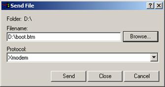
Figure 3-4 Send file dialog box
Step 8: Click <Send>. The system displays the page, as shown in Figure 3-5.

Step 9: After the download completes, the system displays the following information:
Loading ...CCCCCCCCCC done!
Step 10: Reset HyperTerminal’s baud rate to 9600 bps (refer to Step 4 and 5). Then, press any key as prompted. The system will display the following information when it completes the loading.
Bootrom updating.....................................done!
& Note:
l If the HyperTerminal’s baud rate is not reset to 9600 bps, the system prompts "Your baudrate should be set to 9600 bps again! Press enter key when ready".
l You need not reset the HyperTerminal’s baud rate and can skip the last step if you have chosen 9600 bps. In this case, the system upgrades BootROM automatically and prompts “Bootrom updating now.....................................done!”.
2) Loading host software
Follow these steps to load the host software:
Step 1: Select <1> in Boot Menu and press <Enter>. The system displays the following information:
1. Set TFTP protocol parameter
2. Set FTP protocol parameter
3. Set XMODEM protocol parameter
0. Return to boot menu
Enter your choice(0-3):
Step 2: Enter 3 in the above menu to download the host software using XMODEM.
The subsequent steps are the same as those for loading the BootROM software, except that the system gives the prompt for host software loading instead of BootROM loading.
III. Loading Software Using TFTP through Ethernet Port
TFTP, one protocol in TCP/IP protocol suite, is used for trivial file transfer between client and server. It uses UDP to provide unreliable data stream transfer service.
1) Loading BootROM software

Figure 3-6 Local loading using TFTP
Step 1: As shown in Figure 3-6, connect the switch through an Ethernet port to the TFTP server, and connect the switch through the Console port to the configuration PC.
& Note:
You can use one PC as both the configuration device and the TFTP server.
Step2: Run the TFTP server program on the TFTP server, and specify the path of the program to be downloaded.
![]() Caution:
Caution:
TFTP server program is not provided with the H3C S3610&S5510 Series Ethernet Switches.
Step 3: Run the HyperTerminal program on the configuration PC. Start the switch. Then enter the Boot Menu.
At the prompt "Enter your choice(0-9):" in the Boot Menu, press <6> or <Ctrl+U>, and then press <Enter> to enter the BootROM update menu shown below:
Bootrom update menu:
1. Set TFTP protocol parameter
2. Set FTP protocol parameter
3. Set XMODEM protocol parameter
0. Return to boot menu
Enter your choice(0-3):
Step 4: Enter 1 to in the above menu to download the BootROM software using TFTP. Then set the following TFTP-related parameters as required:
Load File name :switch.btm
Switch IP address :1.1.1.2
Server IP address :1.1.1.1
Step 5: Press <Enter>. The system displays the following information:
Are you sure you want to update your bootrom? Yes or No(Y/N)
Step 6: Enter Y to start file downloading or N to return to the Bootrom update menu. If you enter Y, the system begins to download and update the BootROM software. Upon completion, the system displays the following information:
Loading........................................done
Bootrom updating..........done!
2) Loading host software
Follow these steps to load the host software.
Step 1: Select <1> in Boot Menu and press <Enter>. The system displays the following information:
1. Set TFTP protocol parameter
2. Set FTP protocol parameter
3. Set XMODEM protocol parameter
0. Return to boot menu
Enter your choice(0-3):
Step 2: Enter 1 in the above menu to download the host software using TFTP.
The subsequent steps are the same as those for loading the BootROM program, except that the system gives the prompt for host software loading instead of BootROM loading.
![]() Caution:
Caution:
When loading BootROM and host software using Boot menu, you are recommended to use the PC directly connected to the device as TFTP server to promote upgrading reliability.
IV. Loading Software Using FTP through Ethernet Port
FTP is an application-layer protocol in the TCP/IP protocol suite. It is used for file transfer between server and client, and is widely used in IP networks.
You can use the switch as an FTP client or a server, and download software to the switch through an Ethernet port. The following is an example.
1) Loading BootROM software

Figure 3-7 Local loading using FTP client
Step 1: As shown in Figure 3-7, connect the switch through an Ethernet port to the FTP server, and connect the switch through the Console port to the configuration PC.
& Note:
You can use one computer as both configuration device and FTP server.
Step 2: Run the FTP server program on the FTP server, configure an FTP user name and password, and copy the program file to the specified FTP directory.
Step 3: Run the HyperTerminal program on the configuration PC. Start the switch. Then enter the Boot Menu.
At the prompt "Enter your choice(0-9):" in the Boot Menu, press <6> or <Ctrl+U>, and then press <Enter> to enter the BootROM update menu shown below:
Bootrom update menu:
1. Set TFTP protocol parameter
2. Set FTP protocol parameter
3. Set XMODEM protocol parameter
0. Return to boot menu
Enter your choice(0-3):
Step 4: Enter 2 in the above menu to download the BootROM software using FTP. Then set the following FTP-related parameters as required:
Load File name :switch.btm
Switch IP address :10.1.1.2
Server IP address :10.1.1.1
FTP User Name :switch
FTP User Password :hello
Step 5: Press <Enter>. The system displays the following information:
Are you sure you want to update your bootrom? Yes or No(Y/N)
Step 6: Enter Y to start file downloading or N to return to the Bootrom update menu. If you enter Y, the system begins to download and update the program. Upon completion, the system displays the following information:
Loading........................................done
Bootrom updating..........done!
2) Loading host software
Follow these steps to load the host software:
Step 1: Select <1> in Boot Menu and press <Enter>. The system displays the following information:
1. Set TFTP protocol parameter
2. Set FTP protocol parameter
3. Set XMODEM protocol parameter
0. Return to boot menu
Enter your choice(0-3):
Enter 2 in the above menu to download the host software using FTP.
The subsequent steps are the same as those for loading the BootROM program, except for that the system gives the prompt for host software loading instead of BootROM loading.
![]() Caution:
Caution:
When loading BootROM and host software using Boot menu, you are recommended to use the PC directly connected to the device as TFTP server to promote upgrading reliability.
3.2.3 Remote Software Loading
If your terminal is not directly connected to the switch, you can telnet to the switch, and use FTP or TFTP to load BootROM and host software remotely.
I. Remote Loading Using FTP
1) Loading Process Using FTP Client
As shown in Figure 3-8, a PC is used as both the configuration device and the FTP server. You can telnet to the switch, and then execute the FTP commands to download the BootROM program switch.btm from the remote FTP server (with an IP address 10.1.1.1) to the switch.

Figure 3-8 Remote loading using FTP
Step 1: Download the software to the switch using FTP commands.
<Sysname> ftp 10.1.1.1
Trying 10.1.1.1 ...
Press CTRL+K to abort
Connected to 10.1.1.1
220 WFTPD 2.0 service (by Texas Imperial Software) ready for new user
User(192.168.0.144:(none)): switch
331 Give me your password, please
Password:
230 Logged in successfully
[ftp] get switch.btm
227 Entering Passive Mode (10,1,1,1,4,125)
150 "D:\switch.btm" file ready to send (291284 bytes) in ASCII mode
....226 Transfer finished successfully.
FTP: 291284 byte(s) received in 4.393 second(s), 66.00K byte(s)/sec.
[ftp] bye
221 Windows FTP Server (WFTPD, by Texas Imperial Software) says goodbye.
<Sysname>
& Note:
When using different FTP server software on PC, different information will be output to the switch.
Step 2: Update the BootROM program on the switch.
<Sysname> bootrom update file switch.btm
This command will update bootrom file, Continue? [Y/N]y
Now updating bootrom, please wait...
BootRom file updating finished!
Step 3: Restart the switch.
<Sysname> reboot
& Note:
Before restarting the switch, make sure you have saved all other configurations that you want, so as to avoid losing configuration information.
Loading the host software is the same as loading the BootROM program, except for that the file to be downloaded is the host software file, and that you need to use the boot boot-loader command to select the host software at reboot of the switch.
After the above operations, the BootROM and host software loading is completed.
Pay attention to the following:
l The loading of BootROM and host software takes effect only after you restart the switch with the reboot command.
l If the space of the Flash memory is not enough, you can delete the useless files in the Flash memory before software downloading.
l No power-down is permitted during software loading.
2) Loading Process Using FTP Server
As shown in Figure 3-9, the switch is used as the FTP server. You can telnet to the switch, and then execute the FTP commands to download the BootROM program switch.btm from the switch.
3) Loading BootROM

Figure 3-9 Remote loading using FTP server
Step 1: As shown in Figure 3-9, connect the switch through an Ethernet port to the PC (with IP address 10.1.1.1)
Step 2: Configure the IP address of VLAN1 on the switch to 192.168.0.39, and subnet mask to 255.255.255.0.
& Note:
You can configure the IP address for any VLAN on the switch for FTP transmission. However, before configuring the IP address for a VLAN interface, you have to make sure whether the IP addresses of this VLAN and PC are routable.
<Sysname> system-view
[Sysname] interface Vlan-interface 1
[Sysname-Vlan-interface1] ip address 192.168.0.39 255.255.255.0
Step 3: Enable FTP service on the switch, configure the FTP user name to test and password to pass.
[Sysname-Vlan-interface1] quit
[Sysname] ftp server enable
% Start FTP server
[Sysname] local-user test
New local user added.
[Sysname-luser-test] password simple pass
[Sysname-luser-test] service-type ftp
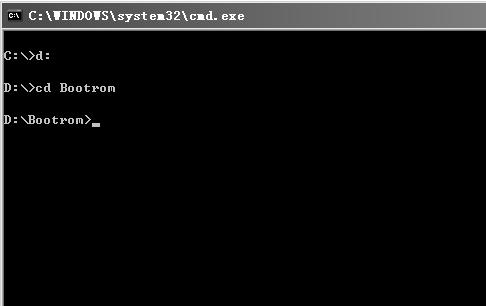
Step 4: Enable FTP client software on PC. Refer to Figure 3-10 for the command line interface in Windows operating system.
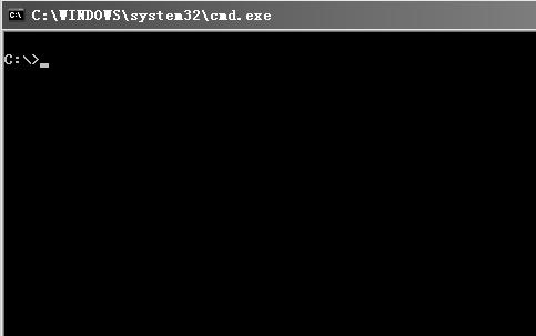
Figure 3-10 Command line interface
Step 5: Enter cd in the interface to switch to the path that the BootROM upgrade file is to be stored, and assume the name of the path is “D:\Bootrom”, as shown in Figure 3-11.
Step 6: Enter “ftp 192.168.0.39” and enter the user name test, password pass, as shown in Figure 3-12, to log on the FTP server.

Figure 3-12 Log on the FTP server
Step 7: Use the put command to upload the file switch.btm to the switch, as shown in Figure 3-13.
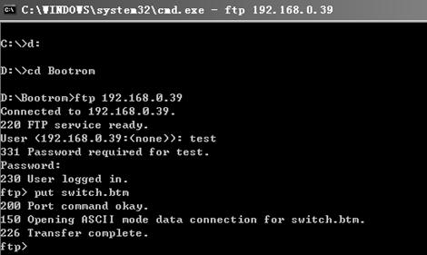
Figure 3-13 Upload file switch.btm to the switch
Step 8: Configure switch.btm to be the BootROM at reboot, and then restart the switch.
<Sysname> bootrom update file switch.btm
This command will update bootrom file, Continue? [Y/N]y
Now updating bootrom, please wait...
BootRom file updating finished!.
<Sysname> reboot
When rebooting the switch, use the file switch.btm as BootROM to finish BootROM loading.
Loading the host software is the same as loading the BootROM program, except for that the file to be downloaded is the host software file, and that you need to use the boot-loader command to select the host software at reboot of the switch.
& Note:
l The steps listed above are performed in the Windows operating system, if you use other FTP client software, refer to the corresponding user’s guide before operation.
l Only the configurations steps concerning loading are illustrated here, for detailed description on the corresponding configuration commands, refer to the chapter “File System Management”.
II. Remote Loading Using TFTP
The remote loading using TFTP is similar to that using FTP. The only difference is that TFTP is used instead off FTP to load software to the switch, and the switch can only act as a TFTP client.
3.3 Device Management Configuration
3.3.1 Rebooting a Device
When a fault occurs to a running device, you can remove the fault by rebooting it, depending on the actual situation. You can set a time at which the device can automatically reboot. You can also set a delay so that the device can automatically reboot in the delay.
Table 3-1 Follow these steps to reboot a device
|
To do… |
Use the command… |
Remarks |
|
Reboot the whole system |
reboot |
Optional |
|
Enable the scheduled reboot function and specify a specific reboot time and date. |
schedule reboot at hh:mm [ date ] |
Optional By default, the scheduled reboot function is disabled. |
|
Enable the scheduled reboot function and specify a reboot wait time. |
schedule reboot delay { hh:mm | mm } |
|
|
Display the reboot time of a device. |
display schedule reboot |
Optional You can carry out the command in any view. |
& Note:
The precision of the device timer is 1 minute. One minute before the reboot time, the device will prompt “REBOOT IN ONE MINUTE” and will reboot in one minute.
You can use the reboot, schedule reboot at, and schedule reboot delay commands to reboot a device. As a result, the ongoing services will be interrupted. You must be careful to use these commands.
3.3.2 Specifying a BootROM File for the Next Device Boot
A BootROM file is an application file adopted by the device. When multiple BootROM files are available on the storage media, you can specify an APP file for the next device boot by executing the following command.
Table 3-2 Follow these steps to specify an APP file for the next device boot
|
To do… |
Use the command… |
Remarks |
|
Specify a BootROM file |
boot-loader file file-url |
Required |
3.3.3 Upgrading a BootROM File
During the operation of the device, you can use the BootROM programs in the storage media to upgrade the running BootROM programs.
Table 3-3 Follow these steps to upgrade a BootROM file
|
To do… |
Use the command… |
Remarks |
|
Upgrade the BootROM file |
bootrom update file file-url |
Required |
& Note:
You need to reboot the device to make the upgraded BootROM program take effect.
3.3.4 Clearing the 16bit Interface Indexes Not Used in the Current System
In practical networks, the network management software requires the device to provide a uniform, stable 16bit interface index. That is, a one-to-one relationship should be kept between the interface name and the interface index in the same device.
For the purpose of the stability of an interface index, the system will save the 16bit interface index when a card or logical interface is removed.
If you repeatedly insert and remove different subcards or interface cards to create or delete a large amount of logical interface, the interface indexes will be used up, which will result in interface creation failures. To avoid such a case, you can clear all 16bit interface indexes saved but not used in the current system in user view.
After the above operation,
l For a re-created interface, the new interface index shall not be consistent with the original one.
l For existing interfaces, their interface indexes shall remain unchanged.
Table 3-4 Follow the step below to clear the 16bit interface indexes not used in the current system
|
To do… |
Use the command… |
Remarks |
|
Clear the 16bit interface indexes not used in the current system |
reset unused porttag |
— |
![]() Caution:
Caution:
3.4 Displaying and Maintaining Device Management Configuration
After the above configuration, you can use the display command in any view to display the operation status of the device, so as to verify the configuration effect.
Table 3-5 Display and maintain device management configuration
|
To do… |
Use the command… |
Remarks |
|
Display the BootROM file used for the next boot. |
display boot-loader |
Available in any view |
|
Display the statistics of the CPU usage |
display cpu-usage [ number [ offset ] [ verbose ] [ from-device ] ] |
|
|
Display information about storage media on the device |
display device [ manuinfo | subslot subslot-number | verbose ] |
|
|
Display the operating state of fans in a device |
display fan [ fan-id ] |
|
|
Display the usage of the memory of a device |
display memory |
|
|
Display the power state of a device |
display power [ power-id ] |
|
|
Display the reboot time of a device |
display schedule reboot |
3.5 Remote Upgrade Configuration Example
I. Network requirements
l The device serves as the FTP client and the remote PC as the FTP server. The switch.bin program and the boot.btm program are both saved under the switch directory of the FTP server.
l The IP address of a VLAN interface on the device is 1.1.1.1/24, the IP address of the FTP server is 2.2.2.2/24, and the route between the device and the FTP server is reachable.
l You can log in to the FTP server via Telnet to download the application program and remotely upgrade the device through command lines.
II. Network diagram

Figure 3-14 Network diagram for FTP configuration
III. Configuration procedure
l Configuration on the FTP server
# Set the FTP username to switch and password to hello.
# Configure the user to have access to the switch directory.
l Configuration on the device
![]() Caution:
Caution:
If the size of the FLASH on the device is not large enough, delete the original application programs from the FLASH before downloading.
# Enter the following command in user view to log in to the FTP server.
<Sysname> ftp 2.2.2.2
Trying 2.2.2.2 ...
Press CTRL+K to abort
Connected to 2.2.2.2
220 WFTPD 2.0 service (by Texas Imperial Software) ready for new user
User(2.2.2.2:(none)):switch
331 Give me your password, please
Password:
230 Logged in successfully
[ftp]
# Enter the authorization directory of the FTP server.
[ftp] cd switch
# Download the switch.bin and boot.btm programs to the FLASH of the device.
[ftp] get switch.bin
[ftp] get boot.btm
# Clear the FTP connection and return to user view.
[ftp] quit
<Sysname>
# Upgrade the BootROM file.
<Sysname> bootrom update file boot.btm
# Specify the application program for the next boot.
<Sysname> boot-loader file switch.bin
# Reboot the device. The application program is upgraded now.
<Sysname> reboot