| Title | Size | Downloads |
|---|---|---|
| RPS Ordering Guide for H3C Low-End Series Ethernet Switches(V1.03)-book.pdf | 160.98 KB |
- Table of Contents
- Related Documents
-
- H3C Low-End Ethernet Switches Configuration Guide(V1.01)
- H3C Low-End Ethernet Switches Configuration Examples(V1.04)
- H3C S3100 Series Ethernet Switches Installation Manual-(V1.06)
- H3C S3100 Series Ethernet Switches Quick Start(V1.08)
- H3C S3100-52P Ethernet Switch Operation Manual-Release 1500(V1.02)
- H3C S3100-52P Ethernet Switch Installation Manual(V1.01)
RPS Overview
Brief Introduction
Hangzhou H3C Technologies Co., Ltd. (hereafter referred to as H3C) offers four models of redundant power system (RPS) units as external DC power supply systems for multiple Ethernet switch models. These RPS models are RPS500-A3, RPS800-A, RPS1000-A3, and RPS1600-A.
The RPS500-A3 and RPS800-A are single-input and single-output RPS units, and the RPS1000-A3 and RPS1600-A, adopting 1+1 redundancy, provide two power module slots. The RPS1000-A3 and RPS1600-A come with one power module by default, and you can use two power modules as needed to enhance the power supply capability of the RPS. The power module models of the RPS1000-A3 and RPS1600-A are FLATPACK1500 and AD162M56-1M1, respectively. Table 1 lists the technical specifications of the RPS models.
Table 1 Technical specifications of the RPS models
|
RPS model |
Input voltage range |
Number of output interfaces |
Output voltage/output current |
Maximum power output |
|
RPS500-A3 |
100 VAC to 240 VAC |
1 |
Available outputs: · –50 V/7.5 A · +12 V/10.5 A |
· –50 V output only: 375 W · +12 V output only: 125 W · –50 V and +12 V outputs concurrently: 500 W |
|
RPS800-A |
100 VAC to 240 VAC |
1 |
Available outputs: · –54 V/12 A · +12 V/17.25 A |
· –54 V output only: 650 W · +12 V output only: 210 W · –54 V and +12 V outputs concurrently: 650 W |
|
RPS1000-A3 |
For each power module: 100 VAC to 240 VAC |
2 |
–54 V/25 A |
Maximum power output when all the eight outputs are working: · With two power modules: 2900 W · With one power module: 1450 W |
|
6 |
–54 V/8 A |
|||
|
RPS1600-A |
2 |
–55 V/25 A |
Maximum power output when all the eight outputs are working: · With two power modules: 3200 W · With one power module: 1600 W |
|
|
6 |
–55 V/8 A |
|
|
NOTE: · The RPS500-A3 and RPS 800-A can provide selective DC power supply to the powered device (PD) depending on the connected DC output cable(s). · Currently, when working as an external power supply system for low-end Ethernet switches, RPS500-A3 or RPS800-A does not use concurrent –50 V/–54 V and +12 V outputs. · The RPS1000-A3 and RPS1600-A can feed multiple devices at the same time. The number of PDs that the RPS unit can support is determined by the power consumption of the PDs and the maximum output power of the RPS unit. The total power consumption contributed by all the PDs must not exceed the maximum output power of the RPS. For more information about the output distribution of the RPS1000-A3 and RPS1600-A, see RPS1000-A3 User Manual and RPS1600-A User Manual. |
RPS Working Mechanism
An RPS unit can serve as a redundant backup power supply unit for switches:
· If using the same AC power source with a PD, when the internal power supply system of the PD fails, the RPS unit can automatically provide DC supply to the PD, thus ensuring uninterrupted operation of the PD.
· If using a different AC power source from a PD, when the AC power source to the PD fails, the RPS unit can automatically provide DC supply to the PD, thus ensuring uninterrupted operation of the PD.
In addition, the RPS1000-A3 and RPS1600-A can provide heavy-duty PoE supply to Ethernet switches.
RPS power supplies of different models work differently. More specifically:
· The RPS1000-A3/RPS1600-A supports hot backup of power supply. When the power supply systems of the PDs operate normally, the RPS1000-A3/RPS1600-A also provides part of the power feed to the device. When the power supply system of a PD fails, the RPS1000-A becomes an independent power supply system to feed that PD.
· The RPS500-A3/RPS800-A supports cold backup of power supply. The RPS500-A3/RPS800-A switches to the DC output state only when it detects a power supply failure of the PD. When the PD’s own power supply system is functioning, the RPS unit only works in monitoring mode, without feeding power to the PD.
|
|
NOTE: · The output of the RPS500-A3 or RPS800-A is controlled by a control pin. When the PD’s own power supply system fails, a LOW signal is sent to the control pin of the RPS unit. Upon receiving this LOW signal, the RPS unit switches to the DC output state within 2 ms. · For some models of PDs, the control pin of the RPS500-A3 or RPS800-A can be controlled through a special cable to support hot backup of power supply. |
DC Output Cables
DC Output Cables for RPS500-A3 and RPS800-A
Table 2 lists the output cables that the RPS500-A3 and RPS800-A use to feed H3C low-end series Ethernet switches. All these cables are optional accessories.
Table 2 Output cable configuration for RPS500-A3 and RPS800-A
|
Cable type |
Code |
Type of output interface (in direction A) |
Type of output interface (in direction B) |
Length |
|
CAB-RPS-1m-3026C |
0404A03C |
H2*7 (4.20) |
H2*7 (4.20) |
1 m (3.28 ft.) |
|
CAB-RPS Pwr-1m-H2X7 |
0404A033 |
|||
|
CAB-RPS500/800-1m |
0404A08G |
|||
|
CAB-Pwr-1m-PS3FP-I |
0404A03V |
JD5-A |
H2*7 (4.20) |
|
|
CAB-Pwr-1m-PS3FP-II |
0404A03U |
JD5 |
H2*7 (4.20) |
|
|
NOTE: A connector of direction A connects to the DC input socket of the switch, and a connector of direction B connects to the DC output interface of the RPS unit. |
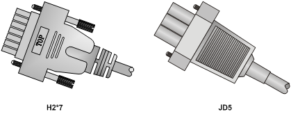
Cables coded 0404A03C, 0404A033, and 0404A08G all use H2*7 connectors. Cables coded 0404A03V and 0404A03U use an H2*7 connector for direction B, and respectively a JD5-A connector and a JD5 connector for direction A. Figure 1 depicts the appearance of H2*7 and JD5 connectors. A JD5-A connector looks like a JD5 expect that a JD5 is a little bigger.
Figure 1 DC output cable connectors
DC Output Cables for RPS1000-A3/RPS1600-A
The RPS1000-A3/RPS1600-A comes with three types of output cables, as listed in Table 3. The output cables of the RPS1000-A3 are required, and those of the RPS1600-A are optional.
Table 3 Output cable configuration for RPS1000-A3/RPS1600-A
|
Cable type |
Code |
Type of output interface (in direction A) |
Type of output interface (in direction B) |
Cable length |
Maximum output current |
|
CAB-RPS PoE-2m-JD5 |
0404A053 |
JD5 |
JD5 |
2 m (6.56 ft.) |
25 A |
|
CAB-RPS Non PoE-2m -JD5-A |
0404A054 |
JD5-A |
JD5-A |
2 m (6.56 ft.) |
8 A |
|
CAB-RPS Non PoE-2m -JD5 |
0404A055 |
JD5-A |
JD5 |
2 m (6.56 ft.) |
25 A |
|
JD5 |
JD5-A |
2 m (6.56 ft.) |
8 A |
|
|
NOTE: · A connector of direction A connects to the DC input socket of the switch, and a connector of direction B connects to the DC output interface of the RPS unit. · A JD5-A connector looks like a JD5 expect that a JD5 is a little bigger. Figure 1 depicts the appearance of H2*7 and JD5 connectors. · To use the PSR750-D for the H3C S5800-60C-PWR, you also need to select the RPS1000-A3/RPS1600-A to provide DC power supply, and use the cable with code 0404A0A1, which is shipped with the PSR750-D. For relevant information, see H3C PSR750-A&PSR750-D Power Modules User Manual. |
Ordering Information for RPS Units and Power Cables
Ordering Information for RPS800-A
Table 4 Support matrix between the RPS800-A, switch and DC power cables
|
Applicable switches |
Applicable DC inputs |
Cables |
|
|
S3100 series |
S3100-26TP-EI-W |
RPS DC interface |
0404A03C |
|
S3600 series |
· S3600-28P-EI · S3600-52P-EI · S3600-28F-EI |
–48 VDC through –60 VDC interface |
0404A03V |
|
S3600V2 series |
· S3600V2-28TP-EI · S3600V2-52TP-EI · S3600V2-28F-EI |
–48 VDC through –60 VDC interface |
0404A03V |
|
S3610 series |
· S3610-52M · S3610-52M-DC |
RPS DC interface |
0404A033 |
|
· S3610-28P · S3610-28TP · S3610-28F · S3610-52P |
–48 VDC through –60 VDC interface |
0404A03V |
|
|
S5100 series |
· S5100-26C-EI · S5100-50C-EI · S5100-24P-EI · S5100-48P-EI |
–48 VDC through –60 VDC interface |
0404A03V |
|
S5120-EI series |
· S5120-28C-EI · S5120-24P-EI · S5120-52C-EI · S5120-48P-EI |
RPS DC interface |
0404A08G |
|
S5120-HI series |
S5120-52SC-HI (uses PSR150-D) |
–48 VDC through –60 VDC interface |
0404A03V |
|
S5500-SI series |
· S5500-28C-SI · S5500-52C-SI |
RPS DC interface |
0404A08G |
|
S5500-EI series |
· S5500-28C-EI · S5500-52C-EI |
RPS DC interface |
0404A08G |
|
S5500-28C-EI-DC |
RPS DC interface |
0404A08G |
|
|
–48 VDC through –60 VDC interface |
0404A03U |
||
|
S5500-28F-EI (uses PSR150-D) |
–48 VDC through –60 VDC interface |
0404A03V |
|
|
S5500-HI series |
· S5500-34C-HI (uses PSR150-D) · S5500-58C-HI (uses PSR150-D) |
–48 VDC through –60 VDC interface |
0404A03V |
|
S5600 series |
· S5600-26C · S5600-50C · S5600-26F |
–48 VDC through –60 VDC interface |
0404A03U |
|
S5800 series |
· S5800-32C · S5800-56C |
RPS DC interface |
0404A08G |
|
S5800-32F (uses PSR150-D) |
–48 VDC through –60 VDC interface |
0404A03V |
|
|
S5800-60C-PWR (uses PSR300-12D1) |
–48 VDC through –60 VDC interface |
0404A03U |
|
|
S5810 series |
S5810-50S (uses PSR300-12D1) |
–48 VDC through –60 VDC interface |
0404A03U |
|
S5820X series |
· S5820X-28S (uses PSR300-12D1) · S5820X-28C (uses PSR300-12D1) |
–48 VDC through –60 VDC interface |
0404A03U |
Ordering Information for RPS500-A3
|
|
NOTE: The RPS500-A3 is phased out, so H3C recommends you to select the RPS800-A as a substitution. |
Table 5 Support matrix between the RPS500-A3, switch and DC power cables
|
Applicable switches |
Applicable DC inputs |
Cables |
|
|
S3100 series |
S3100-26TP-EI-W |
RPS DC interface |
0404A03C |
|
S3600 series |
· S3600-28P-EI · S3600-52P-EI · S3600-28F-EI |
–48 VDC through –60 VDC interface |
0404A03V |
|
S3610 series |
· S3610-52M · S3610-52M-DC |
RPS DC interface |
0404A033 |
|
· S3610-28P · S3610-28TP · S3610-28F · S3610-52P |
–48 VDC through –60 VDC interface |
0404A03V |
|
|
S5100 series |
· S5100-26C-EI · S5100-50C-EI · S5100-24P-EI · S5100-48P-EI |
–48 VDC through –60 VDC interface |
0404A03V |
|
S5120-EI series |
· S5120-28C-EI · S5120-24P-EI · S5120-52C-EI · S5120-48P-EI |
RPS DC interface |
0404A03C |
|
S5500-SI series |
· S5500-28C-SI · S5500-52C-SI |
RPS DC interface |
0404A03C |
|
S5500-EI series |
S5500-28C-EI |
RPS DC interface |
0404A08G |
|
S5500-28C-EI-DC |
RPS DC interface |
0404A08G |
|
|
–48 VDC through –60 VDC interface |
0404A03U |
||
|
S5500-28F-EI (uses PSR150-D) |
–48 VDC through –60 VDC interface |
0404A03V |
|
|
S5600 series |
· S5600-26C · S5600-50C · S5600-26F |
–48 VDC through –60 VDC interface |
0404A03U |
Ordering Information for RPS1600-A
Table 6 Support matrix between the RPS1600-A, switch and DC power cables
|
Applicable switches |
Applicable DC inputs |
Cables |
|
|
Applicable switches of the RPS1600-A -55V/8A outputs |
|||
|
S3600 series |
· S3600-28P-EI · S3600-52P-EI · S3600-28F-EI |
–48 VDC through –60 VDC interface |
0404A054 |
|
S3600V2 series |
· S3600V2-28TP-EI · S3600V2-52TP-EI · S3600V2-28F-EI |
–48 VDC through –60 VDC interface |
0404A054 |
|
S3610 series |
· S3610-28P · S3610-28TP · S3610-28F · S3610-52P |
–48 VDC through –60 VDC interface |
0404A054 |
|
S5120-HI series |
S5120-52SC-HI (uses PSR150-D) |
–48 VDC through –60 VDC interface |
0404A054 |
|
S5500-EI series |
S5500-28C-EI-DC |
–48 VDC through –60 VDC interface |
0404A055 Use a JD5-A connector at the RPS end, and a JD5 connector (a little bigger than the JD5-A) at the switch end. |
|
S5500-28F-EI (uses PSR150-D) |
–48 VDC through –60 VDC interface |
0404A054 |
|
|
S5500-HI series |
· S5500-34C-HI (uses PSR150-D) · S5500-58C-HI (uses PSR150-D) |
–48 VDC through –60 VDC interface |
0404A054 |
|
S5800 series |
S5800-32F (uses PSR150-D) |
–48 VDC through –60 VDC interface |
0404A054 |
|
S5800-60C-PWR (uses PSR300-12D1) |
–48 VDC through –60 VDC interface |
0404A055 Use a JD5-A connector at the RPS end, and a JD5 connector (a little bigger than the JD5-A) at the switch end. |
|
|
S5810 series |
S5810-50S (uses PSR300-12D1) |
–48 VDC through –60 VDC interface |
|
|
S5820X series |
· S5820X-28S (uses PSR300-12D1) · S5820X-28C (uses PSR300-12D1) |
–48 VDC through –60 VDC interface |
|
|
Applicable switches of the RPS1600-A -55V/25A outputs |
|||
|
S3100 series |
S3100-26TP-PWR-EI |
RPS DC interface |
0404A053 |
|
S3100V2 series |
· S3100V2-26TP-PWR-EI · S3100V2-16TP-PWR-EI |
RPS DC interface |
0404A053 |
|
S3600 series |
· S3600-28P-EI · S3600-52P-EI · S3600-28F-EI |
–48 VDC through –60 VDC interface |
0404A055 Use a JD5 connector (a little bigger than the JD5-A) at the RPS end, and a JD5-A connector at the switch end. |
|
· S3600-28P-PWR-EI · S3600-52P-PWR-EI · S3600-28P-PWR-SI · S3600-52P-PWR-SI |
RPS DC interface |
0404A053 |
|
|
S3600V2 series |
· S3600V2-28TP-EI · S3600V2-52TP-EI · S3600V2-28F-EI |
–48 VDC through –60 VDC interface |
0404A055 Use a JD5 connector (a little bigger than the JD5-A) at the RPS end, and a JD5-A connector at the switch end. |
|
· S3600V2-28TP-PWR-SI · S3600V2-52TP-PWR-SI · S3600V2-28TP-PWR-EI · S3600V2-52TP-PWR-EI |
RPS DC interface |
0404A053 |
|
|
S3610 series |
· S3610-28P · S3610-28TP · S3610-28F · S3610-52P |
–48 VDC through –60 VDC interface |
0404A055 Use a JD5 connector (a little bigger than the JD5-A) at the RPS end, and a JD5-A connector at the switch end. |
|
S5120-SI series |
S5120-28P-HPWR-SI |
RPS DC interface |
0404A053 |
|
S5120-EI series |
· S5120-28C-PWR-EI · S5120-52C-PWR-EI |
RPS DC interface |
0404A053 |
|
S5120-HI series |
S5120-52SC-HI (uses PSR150-D) |
–48 VDC through –60 VDC interface |
0404A055 Use a JD5 connector (a little bigger than the JD5-A) at the RPS end, and a JD5-A connector at the switch end. |
|
S5500-SI series |
· S5500-28C-PWR-SI · S5500-52C-PWR-SI |
RPS DC interface |
0404A053 |
|
S5500-EI series |
· S5500-28C-PWR-EI · S5500-52C-PWR-EI |
RPS DC interface |
0404A053 |
|
S5500-28C-EI-DC |
–48 VDC through –60 VDC interface |
0404A053 |
|
|
S5500-28F-EI (uses PSR150-D) |
–48 VDC through –60 VDC interface |
0404A055 Use a JD5 connector (a little bigger than the JD5-A) at the RPS end, and a JD5-A connector at the switch end. |
|
|
S5500-HI series |
· S5500-34C-HI (uses PSR150-D) · S5500-58C-HI (uses PSR150-D) |
–48 VDC through –60 VDC interface |
0404A055 Use a JD5 connector (a little bigger than the JD5-A) at the RPS end, and a JD5-A connector at the switch end. |
|
S5600 series |
· S5600-26C · S5600-50C · S5600-26F |
–48 VDC through –60 VDC interface |
0404A053 |
|
· S5600-26C-PWR · S5600-50C-PWR |
RPS DC interface |
0404A053 |
|
|
S5800 series |
· S5800-32C-PWR · S5800-56C-PWR |
RPS DC interface |
0404A053 |
|
S5800-32F (uses PSR150-D) |
–48 VDC through –60 VDC interface |
0404A055 Use a JD5 connector (a little bigger than the JD5-A) at the RPS end, and a JD5-A connector at the switch end. |
|
|
S5800-60C-PWR (uses PSR300-12D1) |
–48 VDC through –60 VDC interface |
0404A053 |
|
|
S5800-60C-PWR (uses PSR750-D, and RPS1600-A that requires full configuration, that is, two AD162M56-1M1 power modules) |
–48 VDC through –60 VDC interface |
0404A0A1 |
|
|
S5810 series |
S5810-50S (uses PSR300-12D1) |
–48 VDC through –60 VDC interface |
0404A053 |
|
S5820X series |
· S5820X-28S (uses PSR300-12D1) · S5820X-28C (uses PSR300-12D1) |
–48 VDC through –60 VDC interface |
0404A053 |
Ordering Information for RPS1000-A3
|
|
NOTE: The RPS1000-A3 is phased out, so H3C recommends you to select the RPS1600-A as a substitution. |
Table 7 Support matrix between the RPS1000-A3, switch and DC power cables
|
Applicable switches |
Applicable DC inputs |
Cables |
|
|
Applicable switches of the RPS1000-A3 -54V/8A outputs |
|||
|
S3600 series |
· S3600-28P-EI · S3600-52P-EI · S3600-28F-EI |
–48 VDC through –60 VDC interface |
0404A054 |
|
S3610 series |
· S3610-28P · S3610-28TP · S3610-28F · S3610-52P |
–48 VDC through –60 VDC interface |
0404A054 |
|
S5100 series |
· S5100-26C-EI · S5100-50C-EI · S5100-24P-EI · S5100-48P-EI |
–48 VDC through –60 VDC interface |
0404A054 |
|
S5500-EI series |
S5500-28C-EI-DC |
–48 VDC through –60 VDC interface |
0404A055 Use a JD5-A connector at the RPS end, and a JD5 connector (a little bigger than the JD5-A) at the switch end. |
|
S5500-28F-EI (uses PSR150-D) |
–48 VDC through –60 VDC interface |
0404A054 |
|
|
S5800 series |
S5800-32F (uses PSR150-D) |
–48 VDC through –60 VDC interface |
0404A054 |
|
S5800-60C-PWR (uses PSR300-12D1) |
–48 VDC through –60 VDC interface |
0404A055 Use a JD5-A connector at the RPS end, and a JD5 connector (a little bigger than the JD5-A) at the switch end. |
|
|
S5810 series |
S5810-50S (uses PSR300-12D1) |
–48 VDC through –60 VDC interface |
|
|
S5820X series |
· S5820X-28S (uses PSR300-12D1) · S5820X-28C (uses PSR300-12D1) |
–48 VDC through –60 VDC interface |
|
|
Applicable switches of the RPS1000-A3 -54V/25A outputs |
|||
|
S3100 series |
S3100-26TP-PWR-EI |
RPS DC interface |
0404A053 |
|
S3600 series |
· S3600-28P-EI · S3600-52P-EI · S3600-28F-EI |
–48 VDC through –60 VDC interface |
0404A055 Use a JD5 connector (a little bigger than the JD5-A) at the RPS end, and a JD5-A connector at the switch end. |
|
· S3600-28P-PWR-EI · S3600-52P-PWR-EI · S3600-28P-PWR-SI · S3600-52P-PWR-SI |
RPS DC interface |
0404A053 |
|
|
S3610 series |
· S3610-28P · S3610-28TP · S3610-28F · S3610-52P |
–48 VDC through –60 VDC interface |
0404A055 Use a JD5 connector (a little bigger than the JD5-A) at the RPS end, and a JD5-A connector at the switch end. |
|
S5100 series |
· S5100-26C-EI · S5100-50C-EI · S5100-24P-EI · S5100-48P-EI |
–48 VDC through –60 VDC interface |
0404A055 Use a JD5 connector (a little bigger than the JD5-A) at the RPS end, and a JD5-A connector at the switch end. |
|
· S5100-26C-PWR-EI · S5100-50C-PWR-EI |
RPS DC interface |
0404A053 |
|
|
S5120-SI series |
S5120-28P-HPWR-SI |
RPS DC interface |
0404A053 |
|
S5120-EI series |
· S5120-28C-PWR-EI · S5120-52C-PWR-EI |
RPS DC interface |
0404A053 |
|
S5500-SI series |
· S5500-28C-PWR-SI · S5500-52C-PWR-SI |
RPS DC interface |
0404A053 |
|
S5500-EI series |
· S5500-28C-PWR-EI · S5500-52C-PWR-EI |
RPS DC interface |
0404A053 |
|
S5500-28C-EI-DC |
–48 VDC through –60 VDC interface |
0404A053 |
|
|
S5500-28F-EI (uses PSR150-D) |
–48 VDC through –60 VDC interface |
0404A055 Use a JD5 connector (a little bigger than the JD5-A) at the RPS end, and a JD5-A connector at the switch end. |
|
|
S5600 series |
· S5600-26C · S5600-50C · S5600-26F |
–48 VDC through –60 VDC interface |
0404A053 |
|
· S5600-26C-PWR · S5600-50C-PWR |
RPS DC interface |
0404A053 |
|
|
S5800 series |
· S5800-32C-PWR · S5800-56C-PWR |
RPS DC interface |
0404A053 |
|
S5800-32F (uses PSR150-D) |
–48 VDC through –60 VDC interface |
0404A055 Use a JD5 connector (a little bigger than the JD5-A) at the RPS end, and a JD5-A connector at the switch end. |
|
|
S5800-60C-PWR (uses PSR300-12D1) |
–48 VDC through –60 VDC interface |
0404A053 |
|
|
S5800-60C-PWR (uses PSR750-D, and RPS1000-A3 that requires full configuration, that is, two AD162M56-1M1 power modules) |
–48 VDC through –60 VDC interface |
0404A0A1 |
|
|
S5810 series |
S5810-50S (uses PSR300-12D1) |
–48 VDC through –60 VDC interface |
0404A053 |
|
S5820X series |
· S5820X-28S (uses PSR300-12D1) · S5820X-28C (uses PSR300-12D1) |
–48 VDC through –60 VDC interface |
0404A053 |
|
|
NOTE: The models of H3C low-end Ethernet switches supported by the RPS units are subject to changes without prior notice. For the up-to-date information, consult H3C marketing or technical support staff. |
Copyright ©
2008-2011 Hangzhou H3C Technologies Co., Ltd. All rights reserved.
No part of this manual may be reproduced or transmitted in any form or by any
means without prior written consent of Hangzhou H3C Technologies Co., Ltd.
The information in this document is subject to change without notice.
