- Table of Contents
-
- H3C S3610[5510] Series Ethernet Switches Operation Manual-Release 0001-(V1.02)
- 00-1Cover
- 00-2Product Overview
- 01-Login Operation
- 02-VLAN Operation
- 03-IP Address and Performance Operation
- 04-QinQ-BPDU Tunnel Operation
- 05-Port Correlation Configuration Operation
- 06-MAC Address Table Management Operation
- 07-MAC-IP-Port Binding Operation
- 08-MSTP Operation
- 09-Routing Overview Operation
- 10-IPv4 Routing Operation
- 11-IPv6 Routing Operation
- 12-IPv6 Configuration Operation
- 13-Multicast Protocol Operation
- 14-802.1x-HABP-MAC Authentication Operation
- 15-AAA-RADIUS-HWTACACS Operation
- 16-ARP Operation
- 17-DHCP Operation
- 18-ACL Operation
- 19-QoS Operation
- 20-Port Mirroring Operation
- 21-Cluster Management Operation
- 22-UDP Helper Operation
- 23-SNMP-RMON Operation
- 24-NTP Operation
- 25-DNS Operation
- 26-File System Management Operation
- 27-Information Center Operation
- 28-System Maintenance and Debugging Operation
- 29-NQA Operation
- 30-VRRP Operation
- 31-SSH Operation
- 32-Appendix
- Related Documents
-
| Title | Size | Download |
|---|---|---|
| 13-Multicast Protocol Operation | 1 MB |
1.1.1 Comparison of Information Transmission Techniques
1.1.3 Advantages and Applications of Multicast
1.4 Multicast Packets Forwarding Mechanism
Chapter 2 IGMP Snooping Configuration
2.1.1 Principle of IGMP Snooping
2.1.2 Basic Concepts in IGMP Snooping
2.1.3 Work Mechanism of IGMP Snooping
2.1.4 Processing of Multicast Protocol Messages
2.2 IGMP Snooping Configuration Tasks
2.3 Configuring Basic Functions of IGMP Snooping
2.3.1 Configuration Prerequisites
2.3.3 Configuring the Version of IGMP Snooping
2.3.4 Configuring Port Aging Timers
2.4 Configuring IGMP Snooping Port Functions
2.4.1 Configuration Prerequisites
2.4.2 Configuring Static Member Ports
2.4.3 Configuring Simulated Joining
2.4.4 Enabling the Fast Leave Feature
2.4.5 Configuring IGMP Report Suppression
2.5 Configuring IGMP-Related Functions
2.5.1 Configuration Prerequisites
2.5.2 Enabling IGMP Snooping Querier
2.5.4 Configuring Source IP Address of IGMP Queries
2.6 Configuring a Multicast Group Policy
2.6.1 Configuration Prerequisites
2.6.2 Configuring a Multicast Group Filter
2.6.3 Configuring Maximum Multicast Groups that Can Pass Ports
2.6.4 Configuring Multicast Group Replacement
2.7 Displaying and Maintaining IGMP Snooping
2.8 IGMP Snooping Configuration Examples
2.8.1 Configuring Simulated Joining
2.8.2 Static Router Port Configuration
2.9 Troubleshooting IGMP Snooping Configuration
2.9.1 Switch Fails in Layer 2 Multicast Forwarding
2.9.2 Configured Multicast Group Policy Fails to Take Effect
Chapter 3 MLD Snooping Configuration
3.1.2 Basic Concepts in MLD Snooping
3.1.3 Work Mechanism of MLD Snooping
3.2 MLD Snooping Configuration Tasks
3.3 Configuring Basic Functions of MLD Snooping
3.3.1 Configuration Prerequisites
3.3.3 Configuring Port Aging Timers
3.4 Configuring MLD Snooping Port Functions
3.4.1 Configuration Prerequisites
3.4.2 Configuring Static Member Ports
3.4.3 Configuring Simulated Joining
3.4.4 Configuring the Fast Leave Feature
3.4.5 Configuring MLD Report Suppression
3.5 Configuring MLD-Related Functions
3.5.1 Configuration Prerequisites
3.5.2 Enabling MLD Snooping Querier
3.5.4 Configuring Source IPv6 Addresses of MLD Queries
3.6 Configuring an IPv6 Multicast Group Policy
3.6.1 Configuration Prerequisites
3.6.2 Configuring an IPv6 Multicast Group Filter
3.6.3 Configuring Maximum Multicast Groups that Can Pass Ports
3.6.4 Configuring IPv6 Multicast Group Replacement
3.7 Displaying and Maintaining MLD Snooping
3.8 MLD Snooping Configuration Examples
3.8.2 Static Router Port Configuration
3.9 Troubleshooting MLD Snooping
3.9.1 Switch Fails in Layer 2 Multicast Forwarding
3.9.2 Configured IPv6 Multicast Group Policy Fails to Take Effect
Chapter 4 Multicast VLAN Configuration
4.1 Introduction to Multicast VLAN
4.2 Configuring Multicast VLAN
4.4 Multicast VLAN Configuration Example
5.1.2 Work Mechanism of IGMPv1
5.1.3 Enhancements Provided by IGMPv2
5.1.4 Enhancements Provided by IGMPv3
5.3 Configuring Basic Functions of IGMP
5.3.1 Configuration Prerequisites
5.3.3 Configuring IGMP Versions
5.4 Adjusting IGMP Performance
5.4.1 Configuration Prerequisites
5.4.2 Configuring IGMP Message Options
5.4.4 Configure IGMP Fast Leave
5.5 Displaying and Maintaining IGMP
5.6 IGMP Configuration Example
5.7.1 No Multicast Group Member Information on the Receiver-Side Router
5.7.2 Inconsistent Memberships on Routers on the Same Subnet
6.1.5 Introduction to BSR Admin-scope Regions in PIM-SM
6.1.6 SSM Model Implementation in PIM
6.2.1 PIM-DM Configuration Tasks
6.2.2 Configuration Prerequisites
6.2.5 Configuring State Refresh Parameters
6.2.6 Configuring PIM-DM Graft Retry Period
6.3.1 PIM-SM Configuration Tasks
6.3.2 Configuration Prerequisites
6.3.6 Configuring PIM-SM Register Messages
6.3.7 Configuring RPT-to-SPT Switchover
6.4.1 PIM-SSM Configuration Tasks
6.4.2 Configuration Prerequisites
6.4.4 Configuring the Range of PIM-SSM Multicast Groups
6.5 Configuring PIM Common Information
6.5.1 PIM Common Information Configuration Tasks
6.5.2 Configuration Prerequisites
6.5.3 Configuring a PIM Filter
6.5.4 Configuring PIM Hello Options
6.5.5 Configuring PIM Common Timers
6.5.6 Configuring Join/Prune Message Limits
6.6 Displaying and Maintaining PIM
6.7 PIM Configuration Examples
6.7.1 PIM-DM Configuration Example
6.7.2 PIM-SM Configuration Example
6.7.3 PIM-SSM Configuration Example
6.8 Troubleshooting PIM Configuration
6.8.1 Failure of Building a Multicast Distribution Tree Correctly
6.8.2 Multicast Data Abnormally Terminated on an Intermediate Router
6.8.3 RPs Unable to Join SPT in PIM-SM
6.8.4 No Unicast Route Between BSR and C-RPs in PIM-SM
7.1.3 Operation Mechanism of MSDP
7.1.4 MSDP-Related Specifications
7.3 Configuring Basic Functions of MSDP
7.3.1 Configuration Prerequisites
7.3.3 Creating an MSDP Peer Connection
7.3.4 Configuring a Static RPF Peer
7.4 Configuring an MSDP Peer Connection
7.4.1 Configuration Prerequisites
7.4.2 Configuring MSDP Peer Description
7.4.3 Configuring an MSDP Mesh Group
7.4.4 Configuring MSDP Peer Connection Control
7.5.1 Configuration Prerequisites
7.5.2 Configuring SA Message Content
7.5.3 Configuring SA Request Messages
7.5.4 Configuring an SA Message Filtering Rule
7.5.5 Configuring SA Message Cache
7.6 Displaying and Maintaining MSDP
7.7 MSDP Configuration Examples
7.7.1 Example of Configuration Leveraging BGP Routes
7.7.2 Example of Anycast RP Application Configuration
7.7.3 Static RPF Peer Configuration Example
7.8.1 MSDP Peers Stay in Down State
7.8.2 No SA Entries in the Router’s SA Cache
7.8.3 Inter-RP Communication Faults in Anycast RP Application
Chapter 8 Multicast Policy Configuration
8.1.1 Introduction to Multicast Policy
8.1.2 How a Multicast Policy Works
8.3 Configuring a Multicast Policy
8.3.1 Configuration Prerequisites
8.3.2 Enabling IP Multicast Routing
8.3.3 Configuring a Multicast Static Route
8.3.4 Configuring a Multicast Route Match Policy
8.3.5 Configuring Multicast Load Splitting
8.3.6 Configuring Multicast Forwarding Range
8.3.7 Configuring Multicast Forwarding Table Size
8.4 Displaying and Debugging a Multicast Policy
8.5.1 Multicast Static Route Configuration
8.6 Troubleshooting Multicast Policies
8.6.1 Multicast Static Route Failure
8.6.2 Multicast Data Fails to Reach Receivers
Chapter 1 Multicast Overview
1.1 Introduction to Multicast
As a technique coexisting with unicast and broadcast, the multicast technique effectively addresses the issue of point-to-multipoint data transmission. By allowing high-efficiency point-to-multipoint data transmission over a network, multicast greatly saves network bandwidth and reduces network load.
With the multicast technology, a network operator can easily provide new value-added services, such as live Webcasting, Web TV, distance learning, telemedicine, Web radio, real-time videoconferencing, and other information services that have high demands on the bandwidth and real-time data communication.
1.1.1 Comparison of Information Transmission Techniques
I. Unicast
In unicast, the information source sends a separate copy of information to each host that needs the information, as shown in Figure 1-1.
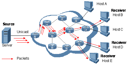
Figure 1-1 Unicast transmission
Assume that Hosts B, D and E need this information. The information source establishes a separate transmission channel for each of these hosts.
In unicast transmission, the traffic over the network is proportional to the number of hosts that need the information, so a tremendous pressure will be imposed on the information source and the network bandwidth if a large number of hosts need the information.
As we can see from the information transmission process, unicast is not suitable for batch transmission of information.
II. Broadcast
In broadcast, the information source sends information to all hosts on the network, even if some hosts do not need the information, as shown in Figure 1-2.
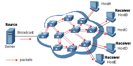
Figure 1-2 Broadcast transmission
Assume that only Hosts B, D, and E need the information. If the information source broadcasts the information, Hosts A and C also receive it. In addition to information security issues, this also causes traffic flooding on the same network.
Therefore, broadcast is disadvantageous in transmitting data to specific hosts; moreover, broadcast transmission is a significant usage of network resources.
III. Multicast
As discussed above, the unicast and broadcast techniques are unable to provide point-to-multipoint data transmissions with the minimum network consumption.
The multicast technique has solved this problem. When some hosts on the network need the information, the multicast source (namely, the information source) sends the information only once. With tree-type routes established for multicast packets through multicast routing protocols, the packets are replicated only where the tree branches, as shown in Figure 1-3:
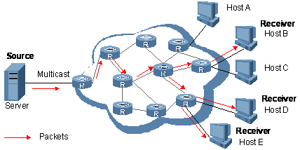
Figure 1-3 Multicast transmission
Assume that Hosts B, D and E need the information. To transmit the information to the right hosts, you can group Hosts B, D and E into a receiver set, and let the routers on the network duplicate and forward the information based on the distribution of the receivers in this set. Finally, the information is correctly delivered to Hosts B, D, and E.
To sum up, multicast has the following advantages:
l Over unicast: As multicast traffic flows to the node the farthest possible from the source before it is replicated and distributed, an increase of the number of hosts will not remarkably add to the network load.
l Over broadcast: As multicast data is sent only to the receivers that need it, multicast uses the network bandwidth reasonably and brings no waste of network resources, and enhances network security.
1.1.2 Roles in Multicast
The following roles are involved in multicast transmission:
l An information sender is referred to as a Multicast Source (“Source” in Figure 1-3).
l Each receiver is a Multicast Group Member (“Receiver” in Figure 1-3).
l All receivers interested in the same information form a Multicast Group. Multicast groups are not subject to geographic restrictions.
l A router capable of multicast routing is called multicast router. In addition to providing the multicast routing function, a multicast router can also manage multicast group members.
For a better understanding of the multicast concept, you can assimilate multicast transmission to transmission of TV programs.
l The TV station (multicast source) transmits a TV program (multicast data) through a channel (multicast group).
l The host tunes his or her TV set (receiver) to the channel (to join the multicast group).
l Then, the TV set can receive the program provided from the TV station (the receiver can receive the multicast data sent by the multicast source).
& Note:
l A multicast source does not necessarily belong to a multicast group. Namely, a multicast source is not necessarily a multicast data receiver.
l Multiple multicast sources can send data to the same multicast group at the same time.
l If there are routers that do not support multicast on the network, multicast routers can encapsulate multicast packets within unicast IP packets and tunnel them to the neighboring multicast routers, which then remove the IP header and multicast the packets. This avoids significant changes to the network structure.
1.1.3 Advantages and Applications of Multicast
I. Advantages of multicast
Advantages of the multicast technique include:
l Enhanced efficiency: reduces the CPU load of information sources and network devices.
l Optimal performance: reduces redundant traffic.
l Distributive application: Enables multiple-point applications at the price of the minimum network resources.
II. Applications of multicast
Applications of the multicast technique include:
l Multimedia and streaming applications, such as Web TV, Web radio, and real-time video/audio conferencing.
l Communication for training and cooperative operations, such as distance learning and telemedicine.
l Data warehouse and financial applications (stock quotes).
l Any other point-to-multiple-point data distribution application.
1.2 Multicast Models
Based on the multicast source processing modes, there are three multicast models:
l Any-Source Multicast (ASM)
l Source-Filtered Multicast (SFM)
l Source-Specific Multicast (SSM)
I. ASM model
In the ASM model, any sender can become a multicast source and send information to a multicast group; numbers of receivers can join a multicast group identified by a group address and obtain multicast information addressed to that multicast group. In this model, receivers are not ware of the position of a multicast source in advance. However, they can join or leave the multicast group at any time.
II. SFM model
The SFM model is derived from the ASM. From the view of a sender, the two models have the same multicast group membership architecture.
Functionally, the SFM model is an extension of the ASM model. In the SFM model, the upper layer software checks the source address of received multicast packets so as to permit or deny multicast traffic from specific sources. Therefore, receivers can receive the multicast data from only part of the multicast sources. From the view of a receiver, multicast sources are not all valid: they are filtered.
III. SSM model
In the practical life, uses may be interested in the multicast data from only certain multicast sources. The SSM model provides a transmission service that allows users to specify the multicast sources they are interested in at the client side.
The radical difference between the SSM model and the ASM model is that in the SSM model, receivers already know the locations of the multicast sources by some other means. In addition, the SSM model uses a multicast address range that is different from that of the ASM module, and dedicated multicast forwarding paths are established between receivers and the specified multicast sources.
& Note:
For details about the concepts of SPT and RPT, refer to PIM Configuration in the IP Multicast Volume.
1.3 Framework of Multicast
IP multicast involves the following questions:
l Where should the multicast source transmit information to? (multicast addressing)
l What receivers exist on the network? (host registration)
l How should information be transmitted to the receivers? (multicast routing)
IP multicast falls in the scope of end-to-end service. The framework of multicast involves the following four parts:
l Addressing mechanism: Information is sent from a multicast source to a group of receivers through a multicast address.
l Host registration: Receiver hosts are allowed to join and leave multicast groups dynamically. This mechanism is the basis for group membership management.
l Multicast routing: A multicast distribution tree (namely a forwarding path tree for multicast data on the network) is constructed for delivering multicast data from a multicast source to receivers.
l Multicast applications: A software system that supports multicast applications, such as video conferencing, must be installed on multicast sources and receiver hosts, and the TCP/IP stack must support reception and transmission of multicast data.
1.3.1 Multicast Addresses
To allow communication between multicast sources and multicast group members, network-layer multicast addresses, namely, multicast IP addresses must be provided. In addition, a technique must be available to map multicast IP addresses to link-layer multicast MAC addresses.
I. IPv4 multicast addresses
Internet Assigned Numbers Authority (IANA) assigned the Class D address space (224.0.0.0 to 239.255.255.255) for IPv4 multicast, as shown in Table 1-1.
Table 1-1 Class D IP address blocks and description
|
Address block |
Description |
|
224.0.0.0 to 224.0.0.255 |
Reserved multicast addresses (addresses for permanent multicast groups). The IP address 224.0.0.0 is reserved, and other IP addresses can be used by routing protocols and for topology searching and protocol maintenance. |
|
224.0.1.0 to 231.255.255.255 233.0.0.0 to 238.255.255.255 |
ASM/SFM multicast addresses available for users (IP addresses of temporary groups). They are globally scoped multicast addresses. |
|
232.0.0.0 to 232.255.255.255 |
Available SSM multicast addresses (IP addresses of temporary groups). They are valid for the entire network. |
|
239.0.0.0 to 239.255.255.255 |
Administratively scoped multicast addresses. These addresses are constrained to a local group or organization. Use of the administratively scoped addresses allows you to define the range of multicast domains flexibly to isolate addresses between different multicast domains, so that the same multicast address can be used in different multicast domains without causing collisions. |
Note that:
1) The membership of a group is dynamic. Hosts can join or leave multicast groups at any time.
2) A multicast group can be either permanent or temporary.
l Permanent group addresses: Multicast addresses reserved by IANA for routing protocols. Such an address identifies a group of specific network devices (also known as reserved multicast groups). For detail, see Table 1-2. A permanent group address will never change. There can be any number of, or even 0, members in a permanent multicast group.
l Temporary group addresses: Group addresses that are temporarily assigned for user multicast groups. Once the number of members of a group comes to 0, the address is released.
Table 1-2 Reserved IPv4 multicast addresses
|
Address |
Description |
|
224.0.0.1 |
All systems on this subnet, including hosts and routers |
|
224.0.0.2 |
All multicast routers on this subnet |
|
224.0.0.3 |
Unassigned |
|
224.0.0.4 |
DVMRP routers |
|
224.0.0.5 |
OSPF routers |
|
224.0.0.6 |
OSPF designated routers/backup designated routers |
|
224.0.0.7 |
ST routers |
|
224.0.0.8 |
ST hosts |
|
224.0.0.9 |
RIPv2 routers |
|
224.0.0.11 |
Mobile agents |
|
224.0.0.12 |
DHCP server / relay agent |
|
224.0.0.13 |
All PIM routers |
|
224.0.0.14 |
RSVP encapsulation |
|
224.0.0.15 |
All CBT routers |
|
224.0.0.16 |
Designated SBM |
|
224.0.0.17 |
All SBMs |
|
224.0.0.18 |
VRRP |
|
…… |
…… |
II. Multicast MAC addresses
When a unicast IP packet is transmitted over an Ethernet network, the destination MAC address is the MAC address of the receiver. When a multicast packet is transmitted over an Ethernet network, however, a multicast MAC address is used as the destination address because the packet is directed a group with an uncertain number of members, rather than to one specific receiver.
As stipulated by IANA, the upper 24 bits of a multicast MAC address are 0 x 01005e, bit 25 is 0, and the lower 23 bits of the MAC address are the lower 23 bits of the multicast IP address. The mapping relationship between a multicast IP address and the corresponding multicast MAC address is shown in Figure 1-4.
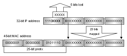
Figure 1-4 Mapping from multicast IP address to multicast MAC address
The upper four bits of a multicast IP address are 1110, representing the multicast flag, and only 23 bits of the remaining 28 bits are mapped to a MAC address, so five bits of the multicast IP address are lost. As a result, 32 multicast IP addresses map to the same MAC address. Therefore, in Layer 2 multicast forwarding, a device may receive some multicast data addressed for other IP multicast groups, and such redundant data needs to be filtered at the upper layer.
III. IPv6 Multicast Addresses
As defined in RFC 2373, the format of an IPv6 multicast is as follows:
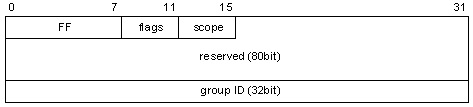
Figure 1-5 IPv6 multicast format
l FF: 8 bits, indicating that this address is an IPv6 multicast address.
l Flags: 4 bits, of which the high-order 3 bits are reserved bits set to 0, and the low-order bit is the Transient (T) flag. When set to 0, the T flag indicates that the multicast address is a permanently-assigned (well-known) multicast address. When set to 1, the T flag indicates that the multicast address is a transient (not permanently assigned) multicast address.
l Scope: 4 bits, indicating the scope of the IPv6 internetwork for which the multicast traffic is intended. Possible values of this field are given in Table 1-3.
l Reserved: 80 bits, all set to 0 currently.
l Group ID: 32 bits, identifying the multicast group. The group ID can be used to create a MAC multicast address. The space of IPv6 multicast addresses can be expanded in the future as required.
Table 1-3 Values of the Scope field
|
Meaning |
|
|
0 |
Reserved |
|
1 |
Node-local scope |
|
2 |
Link-local scope |
|
3, 4, 6, 7, 9 through D |
Unassigned |
|
5 |
Site-local scope |
|
8 |
Organization-local scope |
|
E |
Global scope |
|
F |
Reserved |
1.3.2 Multicast Protocols
IP multicast protocols include multicast group management protocols and multicast routing protocols. Figure 1-6 describes the positions of multicast-related protocols in the network.
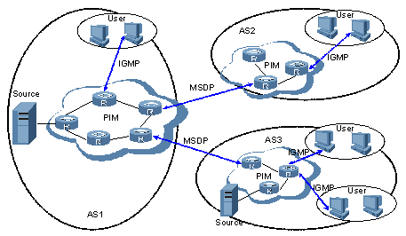
Figure 1-6 Positions of multicast-related protocols
I. Multicast management protocols
Typically, the internet group management protocol (IGMP) is used between hosts and multicast routers directly connected with the hosts. This protocol defines the mechanism of establishing and maintaining group memberships between hosts and multicast routers.
So far, there three IGMP versions: IGMPv1, IGMPv2, and IGMPv3. Newer versions are fully compatible with older ones.
II. Multicast routing protocols
A multicast routing protocol runs between multicast routers to establish and maintain multicast routes and forward multicast packets correctly and efficiently. A multicast route is a loop-free data transmission path from a data source to multiple receivers. Namely, it is a multicast distribution tree.
In the ASM model, multicast routes come in intra-domain routes and inter-domain routes.
l Among a variety of mature intra-domain multicast routing protocols, protocol independent multicast (PIM) is the most commonly used protocol currently. It allows delivery of information to receivers by discovering the multicast source and establishing a multicast distribution tree. Based on the forwarding mechanism, PIM comes in two modes – dense mode and sparse mode.
l The principal issue for inter-domain routes is how the routing information is transmitted between autonomous systems (ASs). So far, multicast source discovery protocol (MSDP) is a mature solution.
For the SSM model, multicast routes are not divided into inter-domain routes and intra-domain routes. Since receivers know the position of the multicast source, channels established through PIM-SD are sufficient for multicast information transport.
1.4 Multicast Packets Forwarding Mechanism
In a multicast model, a multicast source sends information to the host group, which is identified by the multicast group address in the destination address field of the IP packets. Therefore, to deliver multicast packets to receivers located in different parts of the network, multicast routers on the forwarding path usually need to forward multicast packets received on one incoming interface to multiple outgoing interfaces. Compared with a unicast model, a multicast model is more complex in the following aspects.
l To ensure multicast packet transmission in the network, unicast routing tables or multicast routing tables specially provided for multicast must be used as guidance for multicast forwarding.
l To process the same multicast information from different peers received on different interfaces of the same device, every multicast packet is subject to a reverse path forwarding (RPF) check on the incoming interface. The result of the RPF check determines whether the packet will be forwarded or discarded. The RPF check mechanism is the basis for most multicast routing protocols to implement multicast forwarding. For details about RPF, refer to”RPF mechanism”.
Chapter 2 IGMP Snooping Configuration
2.1 IGMP Snooping Overview
Internet Group Management Protocol Snooping (IGMP Snooping) is a multicast constraining mechanism that runs on Layer 2 devices to manage and control multicast groups.
2.1.1 Principle of IGMP Snooping
By analyzing received IGMP messages, a Layer 2 device running IGMP Snooping establishes mappings between ports and multicast MAC addresses and forwards multicast data based on these mappings.
As shown in Figure 2-1, when IGMP Snooping is not running, multicast packets are broadcast to all devices at Layer 2. When IGMP Snooping runs, multicast packets for known multicast groups are multicast to the receivers at Layer 2.
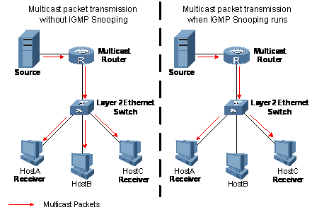
Figure 2-1 Multicast forwarding before and after IGMP Snooping runs
2.1.2 Basic Concepts in IGMP Snooping
I. IGMP Snooping related ports
As shown in Figure 2-2, Router A connects to the multicast source, IGMP Snooping runs on Switch A and Switch B, Host A and Host C are receiver hosts (namely, multicast group members).
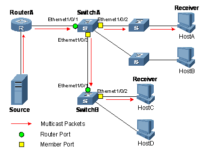
Figure 2-2 IGMP Snooping related ports
Ports involved in IGMP Snooping, as shown in Figure 2-2, are described as follows:
l Router port: On an Ethernet switch, a router port connects the switch to a multicast router. In the figure, Ethernet 1/0/1 of Switch A and Ethernet 1/0/1 of Switch B are router ports. A switch registers all its local router ports in its router port list.
l Member port: On an Ethernet switch, a member port (also known as multicast group member port) connects the switch to a multicast group member. In the figure, Ethernet 1/0/2 and Ethernet 1/0/3 of Switch A and Ethernet1/0/2 of Switch B are member ports. The switch records all member ports on the local device in the IGMP Snooping forwarding table.
& Note:
Whenever mentioned in this document, a router port is a router-connecting port on a switch, rather than a port on a router.
II. Port aging timers in IGMP Snooping and related messages and actions
Table 2-1 Port aging timers in IGMP Snooping and related messages and actions
|
Timer |
Description |
Message before expiry |
Action after expiry |
|
Router port aging timer |
For each router port, the switch sets a timer initialized to the aging time of the route port |
IGMP general query or PIM hello message of which the source address is not 0.0.0.0 |
The switch removes this port from its router port list |
|
Member port aging timer |
When a port joins an multicast group, the switch sets a timer for the port, which is initialized to the member port aging time |
IGMP report message |
The switch removes this port from the multicast group forwarding table |
2.1.3 Work Mechanism of IGMP Snooping
A switch running IGMP Snooping performs different actions when it receives different IGMP messages, as follows:
I. General queries
The IGMP querier periodically sends IGMP general queries to all hosts and routers on the local subnet to find out whether multicast group members exist on the subnet.
Upon receiving an IGMP general query, the switch forwards it through all ports in the VLAN except the receiving port and performs the following to the receiving port:
l If the receiving port is a router port existing in its router port list, the switch resets the aging timer of this router port.
l If the receiving port is not a router port existing in its router port list, the switch adds it into its router port list and sets an aging timer for this router port.
II. Membership reports
A host sends an IGMP report to the multicast router in the following circumstances:
l Upon receiving an IGMP query, a multicast group member host responds with an IGMP report.
l When intended to join a multicast group, a host sends an IGMP report to the multicast router to announce that it is interested in the multicast information addressed to that group.
Upon receiving an IGMP report, the switch forwards it through all the router ports in the VLAN, resolves the address of the multicast group the host has joined, and performs the following to the receiving port:
l If the port is already in the forwarding table, the switch resets the member port aging timer of the port.
l If the port is not in the forwarding table, the switch installs an entry for this port in the forwarding table and starts the member port aging timer of this port.
& Note:
A switch will not forward an IGMP report through a non-router port for the following reason: When IGMP report suppression is enabled, if member hosts of that multicast group still exist under non-router ports, the hosts will stop sending reports when they receive the message, and this prevents the switch from knowing if members of that multicast group are still attached to these ports.
For the description of IGMP report suppression mechanism, refer to ”Chapter 5 IGMP Configuration”.
III. Leave messages
When an IGMPv1 host leaves a multicast group, the host does not send an IGMP leave message, so the switch cannot know immediately that the host has left the multicast group. However, as the host stops sending IGMP reports as soon as it leaves a multicast group, the switch deletes the forwarding entry for the member port corresponding to the host from the forwarding table when its aging timer expires.
When an IGMPv2 or IGMPv3 host leaves a multicast group, the host sends an IGMP leave message to the multicast router to announce that it has leaf the multicast group.
Upon receiving an IGMP leave message on the last member port, a switch forwards it out all router ports in the VLAN. Because the switch does not know whether any other member hosts of that multicast group still exists under the port to which the IGMP leave message arrived, the switch does not immediately delete the forwarding entry corresponding to that port from the forwarding table; instead, it resets the aging timer of the member port.
Upon receiving the IGMP leave message from a host, the IGMP querier resolves from the message the address of the multicast group that the host just left and sends an IGMP group-specific query to that multicast group through the port that received the leave message. Upon receiving the IGMP group-specific query, a switch forwards it through all the router ports in the VLAN and all member ports of that multicast group, and performs the following to the receiving port:
l If a response to an IGMP report from that multicast group arrives to the member port before its aging timer expires, this means that some other members of that multicast group still exist under that port: the switch resets the aging timer of the member port.
l If no IGMP report from that multicast group arrives to this member port before its aging timer expires as a response to the IGMP group-specific query, this means that no members of that multicast group still exist under the port: the switch deletes the forwarding entry corresponding to the port from the forwarding table when the aging timer expires.
2.1.4 Processing of Multicast Protocol Messages
Under different conditions, an IGMP Snooping–capable switch processes multicast protocol messages differently, specifically as follows:
1) If only IGMP is enabled, or both IGMP and PIM are enabled on the switch, the switch handles multicast protocol messages in the normal way.
2) In only PIM is enabled on the switch:
l The switch broadcasts IGMP messages as unknown messages.
l Upon receiving a PIM hello message, the switch will maintain the corresponding router port.
3) When IGMP is disabled on the switch, or when IGMP forwarding entries are cleared (by using the reset igmp group command):
l If PIM is disabled, the switch clears all its Layer 2 multicast entries and router ports.
l If PIM is enabled, the switch clears only its Layer 2 multicast entries without deleting its router ports.
4) When PIM is disabled on the switch:
l If IGMP is disabled, the switch clears all its router ports.
l If IGMP is enabled, the switch maintains all its Layer 2 multicast entries and router ports.
2.2 IGMP Snooping Configuration Tasks
Complete these tasks to configure IGMP Snooping:
|
Task |
Remarks |
|
|
Required |
||
|
Optional |
||
|
Optional |
||
|
Optional |
||
|
Optional |
||
|
Optional |
||
|
Optional |
||
|
Optional |
||
|
Optional |
||
|
Optional |
||
|
Optional |
||
|
Optional |
||
|
Optional |
||
& Note:
l Configurations performed in IGMP Snooping view are effective for all VLANs, while configurations made in VLAN view are effective only for ports belonging to the current VLAN. Configurations made in VLAN view override the corresponding configurations made in IGMP Snooping view.
l Configurations performed in IGMP Snooping view are globally effective; configurations performed in Ethernet port view are effective only for the current port; configurations performed in port group view are effective only for all the ports in the current port group.
l The configurations made in Ethernet port view/port group view take precedence over those made in IGMP Snooping view. The configurations made in IGMP Snooping view are used only if the corresponding configurations have not been made in Ethernet port view/port group view.
2.3 Configuring Basic Functions of IGMP Snooping
2.3.1 Configuration Prerequisites
Before configuring the basic functions of IGMP Snooping, complete the following tasks:
l Configure the corresponding VLANs
l Configure the corresponding port groups
Before configuring the basic functions of IGMP Snooping, prepare the following data:
l Version of IGMP Snooping
l Aging time of router ports
l Aging timer of member ports
2.3.2 Enabling IGMP Snooping
Follow these steps to enabling IGMP Snooping:
|
To do... |
Use the command... |
Remarks |
|
Enter system view |
system-view |
— |
|
Enable IGMP Snooping globally and enter IGMP Snooping view |
igmp-snooping |
Required Disabled by default |
|
Return to system view |
quit |
— |
|
Enter VLAN view |
vlan vlan-id |
— |
|
Enable IGMP Snooping in the VLAN |
igmp-snooping enable |
Required Disabled by default |
& Note:
l IGMP Snooping must be enabled globally before it can be enabled in a VLAN.
l If you enable IGMP Snooping in a specified VLAN, this function takes effect for Ethernet ports in this VLAN only.
2.3.3 Configuring the Version of IGMP Snooping
by configuring the IGMP Snooping version, you are actually configuring the version of IGMP messages that can be analyzed and processed by IGMP Snooping.
l In the case of version 2, IGMP Snooping can analyze and process IGMPv1 and IGMPv2 messages, but not IGMPv3 messages, which will be broadcast in the VLAN.
l If the current is 3, IGMP Snooping can analyze and process IGMPv1, IGMPv2 and IGMPv3 messages.
Follow these steps to configure the version of IGMP Snooping:
|
To do... |
Use the command... |
Remarks |
|
Enter system view |
system-view |
— |
|
Enter VLAN view |
vlan vlan-id |
— |
|
Configure the version of IGMP Snooping |
igmp-snooping version version-number |
Optional Version 2 by default |
![]() Caution:
Caution:
If you switch IGMP Snooping from version 3 to version 2, the system will clear all IGMP Snooping forwarding entries for dynamic joins, and will:
l Keep forwarding entries for version 3 static (*, G) joins;
l Clear forwarding entries for version 3 static (S, G) joins, which will be restored when IGMP Snooping is switched back to version 3.
For details about static joins, Refer to”Configuring Static Member Ports”.
2.3.4 Configuring Port Aging Timers
If the switch does not receive an IGMP general query or a PIM hello message before the aging timer of a router port expires, the switch deletes this port from the router port list when the aging timer times out.
If the switch does not receive an IGMP report from a multicast group before the aging timer of a member port expires, the switch deletes this port from the forwarding table for that multicast group when the aging timers times out.
If multicast group memberships change frequently, you can set a relatively small value for the member port aging timer, and vice versa.
I. Configuring port aging timers globally
Follow these steps to configure port aging timers globally:
|
To do... |
Use the command... |
Remarks |
|
Enter system view |
system-view |
— |
|
Enter IGMP Snooping view |
igmp-snooping |
— |
|
Configure router port aging time |
router-aging-time interval |
Optional 105 seconds by default |
|
Configure member port aging time |
host-aging-time interval |
Optional 260 seconds by default |
II. Configuring port aging timers in a VLAN
Follow these steps to configure port aging timers in a VLAN:
|
To do... |
Use the command... |
Remarks |
|
Enter system view |
system-view |
— |
|
Enter VLAN view |
vlan vlan-id |
— |
|
Configure router port aging time |
igmp-snooping router-aging-time interval |
Optional 105 seconds by default |
|
Configure member port aging time |
igmp-snooping host-aging-time interval |
Optional 260 seconds by default |
2.4 Configuring IGMP Snooping Port Functions
2.4.1 Configuration Prerequisites
Before configuring IGMP Snooping port functions, complete the following task:
l Enable IGMP Snooping in the VLAN or enable IGMP on the desired VLAN interface
Before configuring IGMP Snooping port functions, prepare the following data:
l Multicast group and multicast source addresses
2.4.2 Configuring Static Member Ports
If the host attached to a port is interested in the multicast data addressed to a particular multicast group or the multicast data that a particular multicast source sends to a particular group, you can configure this port to be a group-specific or source-and-group-specific static member port (static (*, G) or (S, G) joining).
In a network with a stable topology structure, you can configure router ports of a switch to be static router ports, through which the switch can receive IGMP messages from routers.
Follow these steps to configure static member ports:
|
To do... |
Use the command... |
Remarks |
|
|
Enter system view |
system-view |
— |
|
|
Enter the corresponding view |
Enter Ethernet port view |
interface interface-type interface-number |
Use either command |
|
Enter port group view |
port-group { manual port-group-name | aggregation agg-id } |
||
|
Configure a static member port |
igmp-snooping static-group group-address [ source-ip source_address ] vlan vlan-id |
Required Disabled by default |
|
|
Configure a static router port |
igmp-snooping static-router-port vlan vlan-id |
Required Disabled by default |
|
& Note:
l When you enable or disable the static (*, G) or (S, G) joining function on a port, the port will not send an unsolicited IGMP report or an IGMP leave message.
l Static member ports and static router ports never age out. To delete such a port, you need to use the corresponding command.
2.4.3 Configuring Simulated Joining
Generally, a host running IGMP responds to IGMP queries from a multicast router. If a host fails to respond due to some reasons, the multicast router will deem that no member of this multicast group exists on the network segment, and therefore will remove the corresponding forwarding path.
To avoid this situation from happening, you can enable simulated joining on a port of the switch, namely configure the port as a simulated member of the multicast group. When an IGMP query arrives, that member port will give a response. As a result, the switch can continue receiving multicast data.
Through this configuration, the following functions can be implemented:
l When an Ethernet port is configured as a simulated member host, it sends an IGMP report.
l When receiving an IGMP general query, the simulated host responds with an IGMP report just like a real host.
l When the simulated joining function is disabled on an Ethernet port, the simulated host sends an IGMP leave message.
Follow these steps to configure simulated joining:
|
To do... |
Use the command... |
Remarks |
|
|
Enter system view |
system-view |
— |
|
|
Enter the corresponding view |
Enter Ethernet port view |
interface interface-type interface-number |
Use either command |
|
Enter port group view |
port-group { manual port-group-name | aggregation agg-id } |
||
|
Configure simulated (*, G) or (S, G) joining |
igmp-snooping host-join group-address [ source-ip source-address ] vlan vlan-id |
Required Disabled by default |
|
& Note:
l Each simulated host is equivalent to an independent host. For example, when receiving an IGMP query, the simulated host corresponding to each configuration responds respectively.
l The IGMP version of a simulated host is the same as the IGMP Snooping version current running on the device.
2.4.4 Enabling the Fast Leave Feature
By default, when receiving a group-specific IGMP leave message on a port, the switch first sends an IGMP group-specific query message that port, rather than directly deleting the port from the multicast forwarding table. If the switch receives no IGMP reports within a certain period of waiting time, it deletes the port from the forwarding table.
I. Configuring the fast leave feature globally
Follow these steps to configure the fast leave feature globally:
|
To do... |
Use the command... |
Remarks |
|
Enter system view |
system-view |
— |
|
Enter IGMP Snooping view |
igmp-snooping |
— |
|
Enable the fast leave feature |
fast-leave [ vlan vlan-list ] |
Required Disabled by default |
II. Configuring the fast leave feature on a port or a group ports
Follow these steps to configure the fast leave feature on a port or a group ports:
|
To do... |
Use the command... |
Remarks |
|
|
Enter system view |
system-view |
— |
|
|
Enter the corresponding view |
Enter Ethernet port view |
interface interface-type interface-number |
Use either command |
|
Enter port group view |
port-group { manual port-group-name | aggregation agg-id } |
||
|
Enable the fast leave feature |
igmp-snooping fast-leave [ vlan vlan-list ] |
Required Disabled by default |
|
![]() Caution:
Caution:
If the fast leave feature is enabled on a port to which more than one host is connected, when one host leaves a multicast group, the other hosts connected to port and interested in the same multicast group will fail to receive multicast data for that group.
2.4.5 Configuring IGMP Report Suppression
When a Layer 2 device receives an IGMP report from a multicast group member, the device forwards the message to the Layer 3 device directly connected with it. Thus, when multiple members belonging to a multicast group exit on the Layer 2 device, the Layer 3 device directly connected with it will receive duplicate IGMP reports from these members.
With the IGMP report suppression function enabled, within a query interval, the Layer 2 device forwards only the first IGMP report of a multicast group to the Layer 3 device and will not forward the subsequent IGMP reports from the same multicast group to the Layer 3 device. This helps reduce the number of packets being transmitted over the network.
Follow these steps to configure IGMP report suppression:
|
To do... |
Use the command... |
Remarks |
|
Enter system view |
system-view |
— |
|
Enter IGMP Snooping view |
igmp-snooping |
— |
|
Enable IGMP report suppression |
report-aggregation |
Optional Enabled by default |
2.5 Configuring IGMP-Related Functions
2.5.1 Configuration Prerequisites
Before configuring IGMP-related functions, complete the following task:
l Enable IGMP Snooping in the VLAN
Before configuring IGMP-related functions, prepare the following data:
l IGMP general query interval
l IGMP last-member query interval
l Maximum response time to IGMP general queries
l Source address of IGMP general queries
l Source address of IGMP group-specific queries
2.5.2 Enabling IGMP Snooping Querier
In a network that does not comprise Layer 3 multicast devices, however, it is a problem to implement an IGMP querier, because Layer 2 device do not support IGMP. To solve this problem, you can enable the IGMP Snooping querier function on a Layer 2 device so that it can work as an IGMP querier to create and maintain multicast forwarding entries at the data link layer.
Follow these steps to enable IGMP Snooping querier:
|
To do... |
Use the command... |
Remarks |
|
Enter system view |
system-view |
— |
|
Enter VLAN view |
vlan vlan-id |
— |
|
Enable IGMP Snooping querier |
igmp-snooping querier |
Required Disabled by default |
![]() Caution:
Caution:
l An IGMP Snooping querier does not take part in IGMP querier elections.
l It is meaningless to configure an IGMP Snooping querier in a multicast network running IGMP. Furthermore, it may affect IGMP querier elections because it sends IGMP general queries that contain low source IP addresses.
2.5.3 Configuring IGMP Timers
You can tune the IGMP general query interval based on actual condition of the network.
Upon receiving an IGMP query (general query or group-specific query), a host starts a timers for each multicast group it has joined. This timer is initialized to a random value in the range of 0 to the maximum response time (the host obtains the value of the maximum response time from the Max Response Time field in the IGMP query it received). When the timer value comes down to 0, the host sends an IGMP report to the corresponding multicast group.
An appropriate setting of the maximum response time for IGMP queries allows hosts to respond to queries quickly and avoids burst of IGMP traffic on the network caused by reports simultaneously sent by a large number of hosts when corresponding timers expires simultaneously.
l For IGMP general queries, you can configure the maximum response time to fill their Max Response time field.
l For IGMP group-specific queries, you can configure the IGMP last-member query interval to fill their Max Response time field. Namely, for IGMP group-specific queries, the maximum response time equals to the IGMP last-member query interval.
I. Configuring IGMP timers globally
Follow these steps to configure IGMP timers globally:
|
To do... |
Use the command... |
Remarks |
|
Enter system view |
system-view |
— |
|
Enter IGMP Snooping view |
igmp-snooping |
— |
|
Configure the maximum response time to IGMP general queries |
max-response-time interval |
Optional 10 seconds by default |
|
Configure the IGMP last-member query interval |
last-member-query-interval interval |
Optional 1 second by default |
II. Configuring IGMP timers in a VLAN
Follow these steps to configure IGMP timers in a VLAN:
|
To do... |
Use the command... |
Remarks |
|
Enter system view |
system-view |
— |
|
Enter VLAN view |
vlan vlan-id |
— |
|
Configure IGMP general query interval |
igmp-snooping query-interval interval |
Optional 60 second by default |
|
Configure the maximum response time to IGMP general queries |
igmp-snooping max-response-time interval |
Optional 10 seconds by default |
|
Configure the IGMP last-member query interval |
igmp-snooping last-member-query-interval interval |
Optional 1 second by default |
![]() Caution:
Caution:
In the configuration, make sure that the IGMP general query interval is larger than the maximum response time for IGMP general queries.
2.5.4 Configuring Source IP Address of IGMP Queries
Upon receiving an IGMP query whose source IP address is 0.0.0.0 on a port, the switch will not set that port as a router port. Therefore, we recommend that you configure a valid IP address as the source IP address of IGMP queries.
Follow these steps to configure source IP address of IGMP queries:
|
To do... |
Use the command... |
Remarks |
|
Enter system view |
system-view |
— |
|
Enter VLAN view |
vlan vlan-id |
— |
|
Configure the source address of IGMP general queries |
igmp-snooping general-query source-ip { current-interface | ip-address } |
Optional 0.0.0.0 by default |
|
Configure the source IP address of IGMP group-specific queries |
igmp-snooping special-query source-ip { current-interface | ip-address } |
Optional 0.0.0.0 by default |
![]() Caution:
Caution:
The source address of IGMP query messages may affect IGMP querier selection within the segment.
2.6 Configuring a Multicast Group Policy
2.6.1 Configuration Prerequisites
Before configuring a multicast group filtering policy, complete the following task:
l Enable IGMP Snooping in the VLAN or enable IGMP on the desired VLAN interface
Before configuring a multicast group filtering policy, prepare the following data:
l ACL rule for multicast group filtering
l The maximum number of multicast groups that can pass the ports
2.6.2 Configuring a Multicast Group Filter
On an IGMP Snooping–enabled switch, the configuration of a multicast group allows the service provider to define limits of multicast programs available to different users.
In an actual application, when a user requests a multicast program, the user’s host initiates an IGMP report. Upon receiving this report message, the switch checks the report against the ACL rule configured on the receiving port. If the receiving port can join this multicast group, the switch adds this port to the IGMP Snooping multicast group list; otherwise the switch drops this report message. Any multicast data that has failed the ACL check will not be sent to this port. In this way, the service provider can control the VOD programs provided for multicast users.
I. Configuring a multicast group filter globally
Follow these steps to configure a multicast group filter globally:
|
To do... |
Use the command... |
Remarks |
|
Enter system view |
system-view |
— |
|
Enter IGMP Snooping view |
igmp-snooping |
— |
|
Configure a multicast group filter |
group-policy acl-number [ vlan vlan-list ] |
Required No filter configured by default |
II. Configuring a multicast group filter on a port or a group ports
Follow these steps to configuring a multicast group filter on a port or a group ports:
|
To do... |
Use the command... |
Remarks |
|
|
Enter system view |
system-view |
— |
|
|
Enter the corresponding view |
Enter Ethernet port view |
interface interface-type interface-number |
Use either command |
|
Enter port group view |
port-group { manual port-group-name | aggregation agg-id } |
||
|
Configure a multicast group filter |
igmp-snooping group-policy acl-number [ vlan vlan-list ] |
Required No filter configured by default |
|
2.6.3 Configuring Maximum Multicast Groups that Can Pass Ports
By configuring the maximum number of multicast groups that can pass a port or a group of ports, you can limit the number of number of multicast programs on-demand available to users, thus to control the traffic on the port.
Follow these steps to configure the maximum number of multicast groups that can pass the port(s):
|
To do... |
Use the command... |
Remarks |
|
|
Enter system view |
system-view |
— |
|
|
Enter the corresponding view |
Enter Ethernet port view |
interface interface-type interface-number |
Use either command |
|
Enter port group view |
port-group { manual port-group-name | aggregation agg-id } |
||
|
Configure the maximum number of multicast groups that can pass the port(s) |
igmp-snooping group-limit limit [ vlan vlan-list ] |
Optional 1,000 by default. |
|
& Note:
l When the number of multicast groups a port has joined reaches the maximum number configured, the system deletes this port from all the related IGMP Snooping forwarding entries, and hosts on this port need to join multicast groups again.
l If you have configured a port to be a static member port or a simulated member of a multicast group, the system deletes this port from all the related IGMP Snooping forwarding entries and applies the configurations again, until the number of multicast groups the port has joined reaches the maximum number configured.
2.6.4 Configuring Multicast Group Replacement
For some special reasons, the number of multicast groups passing through a switch or Ethernet port may exceed the number configured for the switch or the port. To address this situation, you can enable the multicast group replacement function on the switch or certain Ethernet ports. When the number of multicast groups an Ethernet port has joined reaches the limit,
l If the multicast group replacement is enabled, the newly joined multicast group automatically replaces an existing multicast group with the lowest address.
l If the multicast group replacement is not enabled, new IGMP reports will be automatically discarded.
I. Configuring multicast group replacement globally
Follow these steps to configure multicast group replacement globally:
|
To do... |
Use the command... |
Remarks |
|
Enter system view |
system-view |
- |
|
Enter IGMP Snooping view |
igmp-snooping |
- |
|
Configure multicast group replacement |
overflow-replace [ vlan vlan-list ] |
Required Disabled by default |
II. Configuring multicast group replacement on a port or a group port
Follow these steps to configure multicast group replacement on a port or a group ports:
|
To do... |
Use the command... |
Remarks |
|
|
Enter system view |
system-view |
- |
|
|
Enter the corresponding view |
Enter Ethernet port view |
interface interface-type interface-number |
Use either command |
|
Enter port group view |
port-group { manual port-group-name | aggregation agg-id } |
||
|
Configure multicast group replacement |
igmp-snooping overflow-replace [ vlan vlan-list ] |
Required Disabled by default |
|
2.7 Displaying and Maintaining IGMP Snooping
|
To do... |
Use the command... |
Remarks |
|
View the information of multicast groups learned by IGMP Snooping |
display igmp-snooping group [ vlan vlan-id ] [ verbose ] |
Available in any view |
|
View the statistics information of IGMP messages learned by IGMP Snooping |
display igmp-snooping statistics |
Available in any view |
|
Clear IGMP Snooping entries |
reset igmp-snooping group { group-address | all } [ vlan vlan-id ] |
Available in user view |
|
Clear the statistics information of all kinds of IGMP messages learned by IGMP Snooping |
reset igmp-snooping statistics |
Available in user view |
& Note:
l The reset igmp-snooping group command works only on an IGMP Snooping–enabled VLAN, but not on a VLAN with IGMP enabled on its VLAN interface.
l The reset igmp-snooping group command cannot clear IGMP Snooping entries derived from static configuration.
2.8 IGMP Snooping Configuration Examples
2.8.1 Configuring Simulated Joining
I. Network requirements
After the configuration, Host A and Host B, regardless of whether they have joined the multicast group 224.1.1.1, can receive multicast data that the multicast source 1.1.1.1/24 sends to the multicast group 224.1.1.1. Figure 2-3 shows the network connections.
II. Network diagram
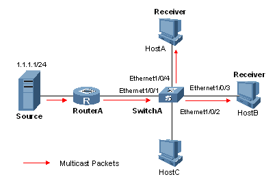
Figure 2-3 Network diagram for simulated joining configuration
III. Configuration procedure
# Create VLAN 100.
<SwitchA> system-view
[SwitchA] vlan 100
# Add ports Ethernet 1/0/1 through Ethernet1/0/4 into VLAN 100.
[SwitchA-vlan100] port Ethernet 1/0/1 to Ethernet 1/0/4
[SwitchA-vlan100] quit
2) Configuring simulated (S, G) joining
# Enable IGMP Snooping in VLAN 100, and set its version to 3.
[SwitchA] igmp-snooping
[SwitchA-igmp-snooping] quit
[SwitchA] vlan 100
[SwitchA-vlan100] igmp-snooping enable
[SwitchA-vlan100] igmp-snooping version 3
[SwitchA-vlan100] quit
# Enable simulated (S, G) joining on Ethernet 1/0/3 and Ethernet 1/0/4 respectively.
[SwitchA] interface Ethernet 1/0/3
[SwitchA-Ethernet1/0/3] igmp-snooping host-join 224.1.1.1 source-ip 1.1.1.1 vlan 100
[SwitchA-Ethernet1/0/3] quit
[SwitchA] interface Ethernet 1/0/4
[SwitchA-Ethernet1/0/4] igmp-snooping host-join 224.1.1.1 source-ip 1.1.1.1 vlan 100
[SwitchA-Ethernet1/0/4] quit
3) Verifying the configuration
# View the detailed information of the multicast group in VLAN 100.
[SwitchA] display igmp-snooping group vlan 100 verbose
Total 1 IP Group(s).
Total 1 IP Source(s).
Total 1 MAC Group(s).
Port flags: D-Dynamic port, S-Static port, A-Aggregation port, C-Copy port
Subvlan flags: R-Real VLAN, C-Copy VLAN
Vlan(id):100.
Total 1 IP Group(s).
Total 1 IP Source(s).
Total 1 MAC Group(s).
Router port(s):total 1 port.
Ethernet1/0/1 (D) ( 00:01:30 )
IP group(s):the following ip group(s) match to one mac group.
IP group address:224.1.1.1
(1.1.1.1, 224.1.1.1):
Attribute: Host Port
Host port(s):total 2 port.
Ethernet1/0/3 (D) ( 00:03:23 )
Ethernet1/0/4 (D) ( 00:03:23 )
MAC group(s):
MAC group address:0100-5e01-0101
Host port(s):total 2 port.
Ethernet1/0/3
Ethernet1/0/4
As shown above, Ethernet 1/0/3 and Ethernet 1/0/4 of Switch A have joined the specified (S, G) entry (1.1.1.1, 224.1.1.1).
2.8.2 Static Router Port Configuration
I. Network requirements
No multicast protocol is running on Router B. After the configuration, Switch A should be able to forward multicast data to Router B. Figure 2-4 shows the network connections.
II. Network diagram
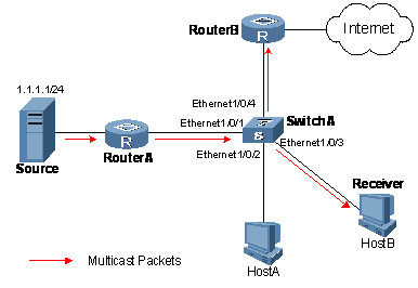
Figure 2-4 Network diagram for static router port configuration
III. Configuration procedure
1) Configuring a VLAN
# Create VLAN 100.
<SwitchA> system-view
[SwitchA] vlan 100
# Add ports Ethernet 1/0/1 through Ethernet1/0/4 into VLAN 100.
[SwitchA-vlan100] port Ethernet 1/0/1 to Ethernet 1/0/4
[SwitchA-vlan100] quit
2) Configuring a static router port
# Enable IGMP Snooping in VLAN 100.
[SwitchA] igmp-snooping
[SwitchA-igmp-snooping] quit
[SwitchA] vlan 100
[SwitchA-vlan100] igmp-snooping enable
[SwitchA-vlan100] quit
# Configure Ethernet 1/0/4 to be a static router port.
[SwitchA] interface Ethernet 1/0/4
[SwitchA-Ethernet1/0/4] igmp-snooping static-router-port vlan 100
[SwitchA-Ethernet1/0/4] quit
3) Verifying the configuration
# View the detailed information of the multicast group in VLAN 100.
[SwitchA] display igmp-snooping group vlan 100 verbose
Total 1 IP Group(s).
Total 1 IP Source(s).
Total 1 MAC Group(s).
Port flags: D-Dynamic port, S-Static port, A-Aggregation port, C-Copy port
Subvlan flags: R-Real VLAN, C-Copy VLAN
Vlan(id):100.
Total 1 IP Group(s).
Total 1 IP Source(s).
Total 1 MAC Group(s).
Router port(s):total 2 port.
Ethernet1/0/1 (D) ( 00:01:30 )
Ethernet1/0/4 (S) ( 00:01:30 )
IP group(s):the following ip group(s) match to one mac group.
IP group address:224.1.1.1
(1.1.1.1, 224.1.1.1):
Attribute: Host Port
Host port(s):total 1 port.
Ethernet1/0/3 (D) ( 00:03:23 )
MAC group(s):
MAC group address:0100-5e01-0101
Host port(s):total 1 port.
Ethernet1/0/3
As shown above, Ethernet 1/0/4 of Switch A has become a static router port.
2.9 Troubleshooting IGMP Snooping Configuration
2.9.1 Switch Fails in Layer 2 Multicast Forwarding
I. Symptom
A switch fails to implement Layer 2 multicast forwarding.
II. Analysis
IGMP Snooping is not enabled.
III. Solution
1) Enter the display current-configuration command to view the running status of IGMP Snooping.
2) If IGMP Snooping is not enabled, use the igmp-snooping command to enable IGMP Snooping globally and then use igmp-snooping enable command to enable IGMP Snooping in VLAN view.
3) If IGMP Snooping is disabled only for the corresponding VLAN, just use the igmp-snooping enable command in VLAN view to enable IGMP Snooping in the corresponding VLAN.
2.9.2 Configured Multicast Group Policy Fails to Take Effect
I. Symptom
Although a multicast group policy has been configured to allow hosts to join specific multicast groups, the hosts can still receive multicast data addressed to other multicast groups.
II. Analysis
l The ACL rule is incorrectly configured.
l The multicast group policy is not correctly applied.
l If a non-existing ACL or null ACL is used as a multicast policy, all multicast groups will be filtered out.
l Certain ports have been configured as static member ports of multicasts groups, and this configuration conflicts with the configured multicast group policy.
III. Solution
1) Use the display acl command to check the configured ACL rule. Make sure that the ACL rule conforms to the multicast group policy to be implemented.
2) Use the display this command in IGMP Snooping view or in the corresponding interface view to check whether the correct multicast group policy has been applied. If not, use the group-policy or igmp-snooping group-policy command to apply the correct multicast group policy.
3) Use the display igmp-snooping group command to check whether any port has been configured as a static member port of any multicast group. If so, check whether this configuration conflicts with the configured multicast group policy. If any conflict exists, remove the port as a static member of the multicast group.
Chapter 3 MLD Snooping Configuration
3.1 MLD Snooping Overview
3.1.1 How MLD Snooping Works
By analyzing received MLD messages, a Layer 2 device running MLD Snooping establishes mappings between ports and multicast MAC addresses and forwards IPv6 multicast data based on these mappings.
As shown in Figure 3-1, when MLD Snooping is not running, IPv6 multicast packets are broadcast to all devices at Layer 2. When MLD Snooping runs, multicast packets for known IPv6 multicast groups are multicast to the receivers at Layer 2.
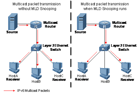
Figure 3-1 IPv6 multicast before and after MLD Snooping runs
3.1.2 Basic Concepts in MLD Snooping
I. MLD Snooping related ports
As shown in Figure 3-2, Router A connects to the multicast source, MLD Snooping runs on Switch A and Switch B, Host A and Host C are receiver hosts (namely, IPv6 multicast group members).
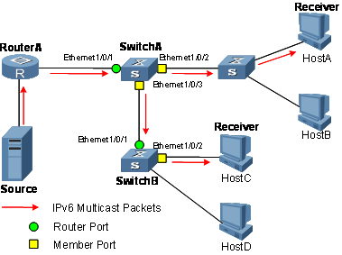
Figure 3-2 MLD Snooping related ports
Ports involved in MLD Snooping, as shown in Figure 3-2, are described as follows:
l Router port: On an Ethernet switch, a router port connects the switch to a multicast router. In the figure, Ethernet 1/0/1 of Switch A and Ethernet 1/0/1 of Switch B are router ports. A switch registers all its local router ports in its router port list.
l Member port: On an Ethernet switch, a member port (also known as IPv6 multicast group member port) connects the switch to an IPv6 multicast group member. In the figure, Ethernet 1/0/2 and Ethernet 1/0/3 of Switch A and Ethernet1/0/2 of Switch B are member ports. The switch records all member ports on the local device in the MLD Snooping forwarding table.
& Note:
Whenever mentioned in this document, a router port is a router-connecting port on a switch, rather than a port on a router.
II. Port aging timers in MLD Snooping
Table 3-1 Port aging timers in MLD Snooping and related messages and actions
|
Timer |
Description |
Message before expiry |
Action after expiry |
|
Router port aging timer |
For each router port, the switch sets a timer initialized to the aging time of the route port |
MLD general query or IPv6 PIM hello message of which the source address is not 0::0 |
The switch removes this port from its router port list |
|
Member port aging timer |
When a port joins an IPv6 multicast group, the switch sets a timer for the port, which is initialized to the member port aging time |
MLD report message |
The switch removes this port from the IPv6 multicast group forwarding table |
3.1.3 Work Mechanism of MLD Snooping
A switch running MLD Snooping performs different actions when it receives different MLD messages, as follows:
I. General queries
Upon receiving an MLD general query, the switch forwards it through all ports in the VLAN except the receiving port and performs the following to the receiving port:
l If the receiving port is a router port existing in its router port list, the switch resets the aging timer of this router port.
l If the receiving port is not a router port existing in its router port list, the switch adds it into its router port list and sets an aging timer for this router port.
II. Membership reports
A host sends an MLD report to the multicast router in the following circumstances:
l Upon receiving an MLD query, an IPv6 multicast group member host responds with an MLD report.
l When intended to join an IPv6 multicast group, a host sends an MLD report to the multicast router to announce that it is interested in the multicast information addressed to that IPv6 multicast group.
Upon receiving an MLD report, the switch forwards it through all the router ports in the VLAN, resolves the address of the IPv6 multicast group the host is has joined, and performs the following to the receiving port:
l If the port is already in the IPv6 forwarding table, the switch resets the member port aging timer of the port.
l If the port is not in the IPv6 forwarding table, the switch installs an entry for this port in the IPv6 forwarding table and starts the member port aging timer of this port.
& Note:
A switch will not forward an MLD report through a non-router port for the following reason: When MLD report suppression is enabled, if member hosts of that IPv6 multicast group still exist under other non-router ports, these hosts will stop sending MLD reports when they receive the message. This prevents the switch from knowing if members of that IPv6 multicast group are still attached to these ports.
III. Done messages
When a host leaves an IPv6 multicast group, the host sends an MLD done message to the multicast router to announce that it is to leave the IPv6 multicast group.
Upon receiving an MLD done message, a switch forwards it through all router ports in the VLAN. Because the switch does not know whether any other member hosts of that IPv6 multicast group still exists under the port to which the MLD done message arrived, the switch does not immediately delete the forwarding entry corresponding to that port from the forwarding table; instead, it resets the aging timer of the member port.
Upon receiving an MLD done message from a host, the MLD querier resolves from the message the address of the IPv6 multicast group that the host just left and sends an MLD group-specific query to that IPv6 multicast group through the port that received the done message. Upon receiving the MLD group-specific query, a switch forwards it through all the router ports in the VLAN and all member ports of that IPv6 multicast group, and performs the following to the receiving port:
l If no MLD report from that IPv6 multicast group arrives to this member port before its aging timer expires as a response to the MLD group-specific query, this means that no members of that IPv6 multicast group still exist under the member port: the switch deletes the forwarding entry for the member port from the forwarding table when its aging timer expires.
3.2 MLD Snooping Configuration Tasks
Complete these tasks to configure MLD Snooping:
|
Task |
Remarks |
|
|
Required |
||
|
Optional |
||
|
Optional |
||
|
Optional |
||
|
Optional |
||
|
Optional |
||
|
Optional |
||
|
Optional |
||
|
Optional |
||
|
Optional |
||
|
Optional |
||
|
Optional |
||
& Note:
l Configurations performed in MLD Snooping view are effective for all VLANs, while configurations made in VLAN view are effective only for ports belonging to the current VLAN. Configurations made in VLAN view override the corresponding configurations made in MLD Snooping view.
l Configurations performed in MLD Snooping view are globally effective; configurations performed in Ethernet port view are effective only for the current port; configurations performed in port group view are effective only for all the ports in the current port group.
l The system gives priority to configurations made in Ethernet port view or port group view. Configurations made in MLD Snooping view are used only if the corresponding configurations have not been carried out in Ethernet port view or port group view.
3.3 Configuring Basic Functions of MLD Snooping
3.3.1 Configuration Prerequisites
Before configuring the basic functions of MLD Snooping, complete the following tasks:
l Configure the corresponding VLANs
l Configure the corresponding port groups
Before configuring the basic functions of MLD Snooping, prepare the following data:
l Aging timer of member ports
3.3.2 Enabling MLD Snooping
Follow these steps to enable MLD Snooping:
|
To do... |
Use the command... |
Remarks |
|
Enter system view |
system-view |
— |
|
Enable MLD Snooping globally and enter MLD Snooping view |
mld-snooping |
Required Disabled by default |
|
Return to system view |
quit |
— |
|
Enter VLAN view |
vlan vlan-id |
— |
|
Enable MLD Snooping in the VLAN |
mld-snooping enable |
Required Disabled by default |
& Note:
l MLD Snooping must be enabled globally before it can be enabled in a VLAN.
l If you enable MLD Snooping in a specified VLAN, this function takes effect for Ethernet ports in this VLAN only.
3.3.3 Configuring Port Aging Timers
If the switch does not receive an MLD general query or an IPv6 PIM hello message before the aging timer of a router port expires, the switch deletes this port from the router port list when the aging timer times out.
If the switch does not receive an MLD report from an IPv6 multicast group before the aging timer of a member port expires, the switch deletes this port from the forwarding table for that IPv6 multicast group when the aging timers times out.
If IPv6 multicast group memberships change frequently, you can set a relatively small value for the member port aging timer, and vice versa.
I. Configuring port aging timers globally
Follow these steps to configure port aging timers globally:
|
To do... |
Use the command... |
Remarks |
|
Enter system view |
system-view |
— |
|
Enter MLD Snooping view |
mld-snooping |
— |
|
Configure router port aging time |
router-aging-time interval |
Optional 260 seconds by default |
|
Configure member port aging time |
host-aging-time interval |
Optional 260 seconds by default |
II. Configuring port aging timers in a VLAN
Follow these steps to configure port aging timers in a VLAN:
|
To do... |
Use the command... |
Remarks |
|
Enter system view |
system-view |
— |
|
Enter VLAN view |
vlan vlan-id |
— |
|
Configure router port aging time |
mld-snooping router-aging-time interval |
Optional 260 seconds by default |
|
Configure member port aging time |
mld-snooping host-aging-time interval |
Optional 260 seconds by default |
3.4 Configuring MLD Snooping Port Functions
3.4.1 Configuration Prerequisites
Before configuring MLD Snooping port functions, complete the following task:
l Enable MLD Snooping in the VLAN
Before configuring MLD Snooping port functions, prepare the following data:
l Address of IPv6 multicast group
3.4.2 Configuring Static Member Ports
In a network with a stable topology structure, you can configure router ports of a switch to be static router ports, through which the switch can receive MLD messages from routers or Layer 3 switches.
Follow these steps to configure static member ports:
|
To do... |
Use the command... |
Remarks |
|
|
Enter system view |
system-view |
— |
|
|
Enter the corresponding view |
Enter Ethernet port view |
interface interface-type interface-number |
Use either command |
|
Enter port group view |
port-group { manual port-group-name | aggregation agg-id } |
||
|
Configure a static member port |
mld-snooping static-group ipv6-group-address vlan vlan-id |
Required Disabled by default |
|
|
Configure a static router port |
mld-snooping static-router-port vlan vlan-id |
Required Disabled by default |
|
l When you configure or remove a port as a static member port for an IPv6 multicast group, the port will not send an unsolicited MLD report or an MLD done message.
l Static member ports and static router ports never age out. To delete such a port, you need to use the corresponding command.
3.4.3 Configuring Simulated Joining
Generally, a host running MLD responds to MLD queries from a multicast router. If a host fails to respond due to some reasons, the multicast router will deem that no member of this IPv6 multicast group exists on the network segment, and therefore will remove the corresponding forwarding path.
To avoid this situation from happening, you can enable simulated joining on a port, namely configure a port of the switch as a simulated member of the IPv6 multicast group. When an MLD query arrives, that member port will give a response. As a result, the switch can continue receiving IPv6 multicast data.
Through this configuration, the following functions can be implemented:
l When an Ethernet port is configured as a simulated member host, it sends an MLD report.
l When receiving an MLD general query, the simulated host responds with an MLD report just like a real host.
Follow these steps to configure simulated joining:
|
To do... |
Use the command... |
Remarks |
|
|
Enter system view |
system-view |
— |
|
|
Enter the corresponding view |
Enter Ethernet port view |
interface interface-type interface-number |
Use either command |
|
Enter port group view |
port-group { manual port-group-name | aggregation agg-id } |
||
|
Configure simulated (*, G) joining |
mld-snooping host-join ipv6-group-address vlan vlan-id |
Required Disabled by default |
|
& Note:
Each simulated host is equivalent to an independent host. For example, when receiving an MLD query, the simulated host corresponding to each configuration responds respectively.
3.4.4 Configuring the Fast Leave Feature
By default, when receiving a group-specific MLD done message on a port, the switch sends a MLD group-specific query message to that port rather than directly deleting the port from the multicast forwarding table. If the switch receives no MLD reports within a certain period of time, it deletes the port from the forwarding table.
With the fast leave feature enabled, when the switch receives a group-specific MLD done message on a port, the switch directly deletes this port from the forwarding table without first sending a MLD group-specific query to the port.
I. Configuring the fast leave feature globally
Follow these steps to configure the fast leave feature globally:
|
To do... |
Use the command... |
Remarks |
|
Enter system view |
system-view |
— |
|
Enter MLD Snooping view |
mld-snooping |
— |
|
Enable the fast leave feature |
fast-leave [ vlan vlan-list ] |
Required Disabled by default |
II. Configuring the fast leave feature on a port or a group ports
Follow these steps to configure the fast leave feature on a port or a group ports:
|
To do... |
Use the command... |
Remarks |
|
|
Enter system view |
system-view |
— |
|
|
Enter the corresponding view |
Enter Ethernet port view |
interface interface-type interface-number |
Use either command |
|
Enter port group view |
port-group { manual port-group-name | aggregation agg-id } |
||
|
Enable the fast leave feature |
mld-snooping fast-leave [ vlan vlan-list ] |
Required Disabled by default |
|
![]() Caution:
Caution:
If the fast leave feature is enabled on a port to which more than one host is connected, when one host leaves an IPv6 multicast group, the other hosts connected to port and interested in the same IPv6 multicast group will fail to receive IPv6 multicast data addressed to that group.
3.4.5 Configuring MLD Report Suppression
With the MLD report suppression function enabled, within a query interval, the Layer 2 device forwards only the first MLD report of an IPv6 group to the Layer 3 device and will not forward the subsequent MLD reports from the same multicast group to the Layer 3 device. This helps reduce the number of packets being transmitted over the network.
Follow these steps to configure MLD report suppression:
|
To do... |
Use the command... |
Remarks |
|
Enter system view |
system-view |
— |
|
Enter MLD Snooping view |
mld-snooping |
— |
|
Enable MLD report suppression |
report-aggregation |
Optional Enabled by default |
3.5 Configuring MLD-Related Functions
3.5.1 Configuration Prerequisites
Before configuring MLD-related functions, complete the following task:
l Enable MLD Snooping in the VLAN
Before configuring MLD-related functions, prepare the following data:
l MLD general query interval
l MLD last-member query interval
l Maximum response time for MLD general queries
l Source IPv6 address of MLD general queries
l Source IPv6 address of MLD group-specific queries
3.5.2 Enabling MLD Snooping Querier
In an IPv6 multicast network running MLD, a Layer 3 multicast device acts as the MLD querier, responsible for sending MLD queries.
In a network that does not comprise Layer 3 multicast devices, however, it is a problem to implement an MLD querier, because Layer 2 device do not support MLD. To solve this problem, you can enable the MLD Snooping querier function on a Layer 2 device so that it can work as an MLD querier to create and maintain IPv6 multicast forwarding entries at the data link layer.
Follow these steps to enable the MLD Snooping querier:
|
To do... |
Use the command... |
Remarks |
|
Enter system view |
system-view |
— |
|
Enter VLAN view |
vlan vlan-id |
— |
|
Enable the MLD Snooping querier |
mld-snooping querier |
Required Disabled by default |
![]() Caution:
Caution:
l The MLD Snooping querier does not take part in MLD querier elections.
l It is meaningless to configure an MLD Snooping querier in an IPv6 multicast network running MLD. Furthermore, it may affect MLD querier elections because it sends MLD general queries that contain low source IPv6 addresses.
3.5.3 Configuring MLD Timers
You can tune the MLD general query interval based on actual condition of the network.
Upon receiving an MLD query (general query or group-specific query), a host starts a timers for each IPv6 multicast group it has joined. This timer is initialized to a random value in the range of 0 to the maximum response time (the host obtains the value of the maximum response time from the Max Response Time field in the MLD query it received). When the timer value comes down to 0, the host sends an MLD report to the corresponding IPv6 multicast group.
An appropriate setting of the maximum response time for MLD queries allows hosts to respond to queries quickly and avoids burst of MLD traffic on the network caused by reports simultaneously sent by a large number of hosts when corresponding timers expires simultaneously.
l For MLD general queries, you can configure the maximum response time to fill their Max Response time field.
l For MLD group-specific queries, you can configure the MLD last-member query interval to fill their Max Response time field. Namely, for MLD group-specific queries, the maximum response time equals to the MLD last-member query interval.
I. Configuring MLD timers globally
Follow these steps to configure MLD timers globally:
|
To do... |
Use the command... |
Remarks |
|
Enter system view |
system-view |
— |
|
Enter MLD Snooping view |
mld-snooping |
— |
|
Configure the maximum response time for MLD general queries |
max-response-time interval |
Optional 10 seconds by default |
|
Configure the MLD last-member query interval |
last-member-query-interval interval |
Optional 1 second by default |
II. Configuring MLD timers in a VLAN
Follow these steps to configure MLD timers in a VLAN
|
To do... |
Use the command... |
Remarks |
|
Enter system view |
system-view |
— |
|
Enter VLAN view |
vlan vlan-id |
— |
|
Configure MLD general query interval |
mld-snooping query-interval interval |
Optional 125 seconds by default |
|
Configure the maximum response time for MLD general queries |
mld-snooping max-response-time interval |
Optional 10 seconds by default |
|
Configure the MLD last-member query interval |
mld-snooping last-member-query-interval interval |
Optional 1 second by default |
![]() Caution:
Caution:
In the configuration, make sure that the MLD general query interval is larger than the maximum response time for MLD general queries.
3.5.4 Configuring Source IPv6 Addresses of MLD Queries
Follow these steps to configure source IPv6 addresses of MLD queries:
|
To do... |
Use the command... |
Remarks |
|
Enter system view |
system-view |
— |
|
Enter VLAN view |
vlan vlan-id |
— |
|
Configure the source IPv6 address of MLD general queries |
mld-snooping general-query source-ip { current-interface | ipv6-address } |
Optional fe80::02ff:ffff:fe00:0001 by default |
|
Configure the source IPv6 address of MLD group-specific queries |
mld-snooping special-query source-ip { current-interface | ipv6-address } |
Optional ffe80::02ff:ffff:fe00:0001 by default |
![]() Caution:
Caution:
The source IPv6 address of MLD query messages may affect MLD querier selection within the segment.
3.6 Configuring an IPv6 Multicast Group Policy
3.6.1 Configuration Prerequisites
Before configuring an IPv6 multicast group filtering policy, complete the following tasks:
l Enable MLD Snooping in the VLAN
Before configuring an IPv6 multicast group filtering policy, prepare the following data:
l IPv6 ACL rule for IPv6 multicast group filtering
l The maximum number of IPv6 multicast groups that can pass the ports
3.6.2 Configuring an IPv6 Multicast Group Filter
On a MLD Snooping–enabled switch, the configuration of an IPv6 multicast group filter allows the service provider to define limits of multicast programs available to different users.
In an actual application, when a user requests a multicast program, the user’s host initiates an MLD report. Upon receiving this report message, the switch checks the report against the ACL rule configured on the receiving port. If this receiving port can join this IPv6 multicast group, the switch adds this port to the MLD Snooping multicast group list; otherwise the switch drops this report message. Any IPv6 multicast data that fails the ACL check will not be sent to this port. In this way, the service provider can control the VOD programs provided for multicast users.
I. Configuring an IPv6 multicast group filter globally
Follow these steps to configure an IPv6 multicast group globally:
|
To do... |
Use the command... |
Remarks |
|
Enter system view |
system-view |
— |
|
Enter MLD Snooping view |
mld-snooping |
— |
|
Configure an IPv6 multicast group filter |
group-policy acl6-number [ vlan vlan-list ] |
Required No IPv6 filter configured by default |
II. Configuring an IPv6 multicast group filter on a port or a group ports
Follow these steps to configure an IPv6 multicast group filer on a port or a group ports:
|
To do... |
Use the command... |
Remarks |
|
|
Enter system view |
system-view |
— |
|
|
Enter the corresponding view |
Enter Ethernet port view |
interface interface-type interface-number |
Use either command |
|
Enter port group view |
port-group { manual port-group-name | aggregation agg-id } |
||
|
Configure an IPv6 multicast group filter |
mld-snooping group-policy acl6-number [ vlan vlan-list ] |
Required No Ipv6 filter configured by default |
|
3.6.3 Configuring Maximum Multicast Groups that Can Pass Ports
By configuring the maximum number of IPv6 multicast groups that can pass a port or a group of ports, you can limit the number of number of multicast programs available to VOD users, thus to control the traffic on the port.
Follow these steps configure the maximum number of IPv6 multicast groups that can pass a port or a group of ports:
|
To do... |
Use the command... |
Remarks |
|
|
Enter system view |
system-view |
— |
|
|
Enter the corresponding view |
Enter Ethernet port view |
interface interface-type interface-number |
Use either command |
|
Enter port group view |
port-group { manual port-group-name | aggregation agg-id } |
||
|
Configure the maximum number of IPv6 multicast groups that can pass the port(s) |
mld-snooping group-limit limit [ vlan vlan-list ] |
Optional The default is 1,000. |
|
& Note:
l When the number of IPv6 multicast groups a port has joined reaches the maximum number configured, the system deletes this port from all the related MLD Snooping forwarding entries, and hosts on this port need to join IPv6 multicast groups again.
l If you have configured a port to be as static member port or enabled the function of simulating a member host on a port, the system deletes this port from all the related MLD Snooping forwarding entries and applies the new configurations, until the number of IPv6 multicast groups the has joined reaches the maximum number configured.
3.6.4 Configuring IPv6 Multicast Group Replacement
For some special reasons, the number of IPv6 multicast groups passing through a switch or Ethernet port may exceed the number configured for the switch or the port. To address this situation, you can enable the IPv6 multicast group replacement function on the switch or certain Ethernet ports. When the number of IPv6 multicast groups an Ethernet port has joined exceeds the limit,
l If the IPv6 multicast group replacement is enabled, the newly joined IPv6 multicast group automatically replaces an existing IPv6 multicast group with the lowest IPv6 address.
l If the IPv6 multicast group replacement is not enabled, new MLD reports will be automatically discarded.
I. Configuring IPv6 multicast group replacement globally
Follow these steps to configure IPv6 multicast group replacement globally:
|
To do... |
Use the command... |
Remarks |
|
Enter system view |
system-view |
— |
|
Enter MLD Snooping view |
mld-snooping |
— |
|
Configure IPv6 multicast group replacement |
overflow-replace [ vlan vlan-list ] |
Required Disabled by default |
II. Configuring IPv6 multicast group replacement on a port or a group ports
Follow these steps to configure IPv6 multicast group replacement on a port or a group ports:
|
To do... |
Use the command... |
Remarks |
|
|
Enter system view |
system-view |
— |
|
|
Enter the corresponding view |
Enter Ethernet port view |
interface interface-type interface-number |
Use either command |
|
Enter port group view |
port-group { manual port-group-name | aggregation agg-id } |
||
|
Configure IPv6 multicast group replacement |
mld-snooping overflow-replace [ vlan vlan-list ] |
Required Disabled by default |
|
3.7 Displaying and Maintaining MLD Snooping
|
To do… |
Use the command... |
Remarks |
|
View the information of IPv6 multicast groups learned by MLD Snooping |
display mld-snooping group [ vlan vlan-id ] [ verbose ] |
Available in any view |
|
Available in any view |
||
|
View the statistics information of MLD messages learned by MLD Snooping |
display mld-snooping statistics |
Available in any view |
|
Clear MLD Snooping entries |
reset mld-snooping group { ipv6-group-address | all } [ vlan vlan-id ] |
Available in user view |
|
Clear the statistics information of all kinds of MLD messages learned by MLD Snooping |
reset mld-snooping statistics |
Available in user view |
& Note:
The reset mld-snooping group command cannot clear MLD Snooping entries derived from static configuration.
3.8 MLD Snooping Configuration Examples
3.8.1 Simulated Joining
I. Network requirements
After the configuration, Host A and Host B, regardless of whether they have joined the IPv6 multicast group FF1E::1, can receive IPv6 multicast data addressed to the IPv6 multicast group FF1E::1. Figure 3-3 shows the network connections.
II. Network diagram
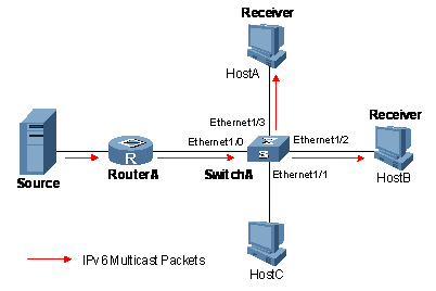
Figure 3-3 Network diagram for simulated joining configuration
III. Configuration procedure
1) Configuring a VLAN
# Create VLAN 100.
<SwitchA> system-view
[SwitchA] vlan 100
# Add Ethernet 1/0/1 through Ethernet1/0/4 into VLAN 100.
[SwitchA-vlan100] port Ethernet 1/0/1 to Ethernet 1/0/4
[SwitchA-vlan100] quit
2) Configuring simulated (*, G) joining
# Enable MLD Snooping in VLAN 100.
[SwitchA] mld-snooping
[SwitchA-mld-snooping] quit
[SwitchA] vlan 100
[SwitchA-vlan100] mld-snooping enable
[SwitchA-vlan100] quit
# Enable simulated (*, G) joining on Ethernet 1/0/3 and Ethernet1/0/4.
[SwitchA] interface Ethernet 1/0/3
[SwitchA-Ethernet1/0/3] mld-snooping host-join ff1e::1 vlan 100
[SwitchA-Ethernet1/0/3] quit
[SwitchA] interface Ethernet 1/0/4
[SwitchA-Ethernet1/0/4] mld-snooping host-join ff1e::1 vlan 100
[SwitchA-Ethernet1/0/4] quit
3) Verifying the configuration
# View the detailed information of the IPv6 multicast group in VLAN 100.
[SwitchA] display mld-snooping group vlan 100 verbose
Total 1 IP Group(s).
Total 1 IP Source(s).
Total 1 MAC Group(s).
Port flags: D-Dynamic port, S-Static port, A-Aggregation port, C-Copy port
Subvlan flags: R-Real VLAN, C-Copy VLAN
Vlan(id):100.
Total 1 IP Group(s).
Total 1 IP Source(s).
Total 1 MAC Group(s).
Router port(s):total 1 port.
Ethernet1/0/1 (D) ( 00:01:30 )
IP group(s):the following ip group(s) match to one mac group.
IP group address:FF1E::1
(::, FF1E::1):
Attribute: Host Port
Host port(s):total 2 port.
Ethernet 1/0/3 (D) ( 00:03:23 )
Ethernet 1/0/4 (D) ( 00:03:23 )
MAC group(s):
MAC group address:3333-0000-0001
Host port(s):total 2 port.
Ethernet 1/0/3
Ethernet 1/0/4
As shown above, Ethernet 1/0/3 and Ethernet 1/0/4 of Switch A have joined IPv6 multicast group ff1e::1.
3.8.2 Static Router Port Configuration
I. Network requirements
No multicast protocol is running on Router B. After the configuration, Switch A should be able to forward IPv6 multicast data to Router B. Figure 3-4 shows the network connections.
II. Network diagram
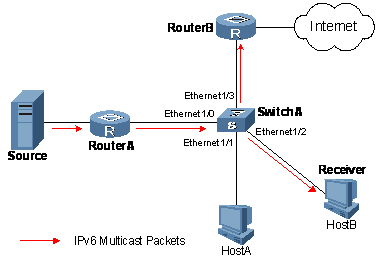
Figure 3-4 Network diagram for static router port configuration
III. Configuration procedure
1) Configuring a VLAN
# Create VLAN 100.
<SwitchA> system-view
[SwitchA] vlan 100
# Add ports Ethernet 1/0/1 through Ethernet1/0/4 into VLAN 100.
[SwitchA-vlan100] port Ethernet 1/0/1 to Ethernet 1/0/4
[SwitchA-vlan100] quit
2) Configuring a static router port
# Enable MLD Snooping in VLAN 100.
[SwitchA] mld-snooping
[SwitchA-mld-snooping] quit
[SwitchA] vlan 100
[SwitchA-vlan100] mld-snooping enable
[SwitchA-vlan100] quit
# Configure Ethernet 1/0/4 to be a static router port.
[SwitchA] interface Ethernet 1/0/4
[SwitchA-Ethernet1/0/4] mld-snooping static-router-port vlan 100
[SwitchA-Ethernet1/0/4] quit
3) Verify the configuration
# View the detailed information of the IPv6 multicast group in VLAN 100.
[SwitchA] display mld-snooping group vlan 100 verbose
Total 1 IP Group(s).
Total 1 IP Source(s).
Total 1 MAC Group(s).
Port flags: D-Dynamic port, S-Static port, A-Aggregation port, C-Copy port
Subvlan flags: R-Real VLAN, C-Copy VLAN
Vlan(id):100.
Total 1 IP Group(s).
Total 1 IP Source(s).
Total 1 MAC Group(s).
Router port(s):total 2 port.
Ethernet 1/0/1 (D) ( 00:01:30 )
Ethernet 1/0/4 (S) ( 00:01:30 )
IP group(s):the following ip group(s) match to one mac group.
IP group address:FF1E::1
(::, FF1E::1):
Attribute: Host Port
Host port(s):total 1 port.
Ethernet 1/0/3 (D) ( 00:03:23 )
MAC group(s):
MAC group address:3333-0000-0001
Host port(s):total 1 port.
Ethernet 1/0/3
As shown above, Ethernet 1/0/4 of Switch A has become a static router port.
3.9 Troubleshooting MLD Snooping
3.9.1 Switch Fails in Layer 2 Multicast Forwarding
I. Symptom
A switch fails to implement Layer 2 multicast forwarding.
II. Analysis
MLD Snooping is not enabled.
III. Solution
1) Enter the display current-configuration command to view the running status of MLD Snooping.
2) If MLD Snooping is not enabled, use the mld-snooping command to enable MLD Snooping globally and then use mld-snooping enable command to enable MLD Snooping in VLAN view.
3) If MLD Snooping is disabled only for the corresponding VLAN, just use the mld-snooping enable command in VLAN view to enable MLD Snooping in the corresponding VLAN.
3.9.2 Configured IPv6 Multicast Group Policy Fails to Take Effect
I. Symptom
Although an IPv6 multicast group policy has been configured to allow hosts to join specific IPv6 multicast groups, the hosts can still receive IPv6 multicast data addressed to other groups.
II. Analysis
l The IPv6 ACL rule is incorrectly configured.
l The IPv6 multicast group policy is not correctly applied. If an inexistent IPv6 ACL or a null IPv6 ACL is used as the IPv6 multicast policy, all IPv6 multicast groups will be filtered out.
l Certain ports have been configured as static member ports of IPv6 multicasts groups, and this configuration conflicts with the configured IPv6 multicast group policy.
III. Solution
1) Use the display acl ipv6 command to check the configured IPv6 ACL rule. Make sure that the IPv6 ACL rule conforms to the IPv6 multicast group policy to be implemented.
2) Use the display this command in MLD Snooping view or the corresponding port view to check whether the correct IPv6 multicast group policy has been applied. If not, use the group-policy or mld-snooping group-policy command to apply the correct IPv6 multicast group policy.
3) Use the display mld-snooping group command to check whether any port has been configured as a static member port of any IPv6 multicast group. If so, check whether this configuration conflicts with the configured IPv6 multicast group policy. If any conflict exists, remove the port as a static member of the IPv6 multicast group.
Chapter 4 Multicast VLAN Configuration
4.1 Introduction to Multicast VLAN
As shown in Figure 4-1, in the traditional multicast programs-on-demand mode, when hosts that belong to different VLANs, Host A, Host B and Host C require multicast programs on demand service, Router A needs to forward a separate copy of the multicast data in each VLAN. This results in not only waste of network bandwidth but also extra burden on the Layer 3 device.
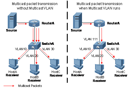
Figure 4-1 Before and after multicast VLAN is enabled on the Layer 2 device
To solve this problem, you can enable the multicast VLAN feature on Switch A, namely configure the VLANs to which these hosts belong as sub-VLANs of a multicast VLAN on the Layer 2 device and enable Layer 2 multicast in the multicast VLAN. After this configuration, Router A replicates the multicast data only within the multicast VLAN instead of forwarding a separate copy of the multicast data to each VLAN. This saves the network bandwidth and lessens the burden of the Layer 3 device.
4.2 Configuring Multicast VLAN
Follow these steps to configure a multicast VLAN:
|
To do… |
Use the command… |
Remarks |
|
Enter system view |
system-view |
— |
|
Configure a specific VLAN as a multicast VLAN |
multicast-vlan vlan-id enable |
Required Disabled by default |
|
Configure sub-VLANs for a specific multicast VLAN |
multicast-vlan vlan-id subvlan vlan-list |
Required No sub-VLAN by default. |
& Note:
l The VLAN to be configured as the multicast VLAN and the VLANs to be configured as sub-VLANs of the multicast VLAN must exist.
l The VLANs to be configured as sub-VLANs of the multicast VLAN must not be multicast VLANs
l The VLANs to be configured as the sub-VLANs of the multicast VLAN must not be sub-VLANs of another multicast VLAN
l The total number of sub-VLANs of multicast VLANs must not exceed the system limit. A S3610&S5510 switch supports 16 multicast VLANs, with each VLAN supporting up to 1,000 sub-VLANs. But the total number of sub-VLANs cannot exceed 1,000.
![]() Caution:
Caution:
l You cannot configure any multicast VLAN or a sub-VLAN of a multicast VLAN on a device with the Layer 3 multicast enabled.
l After a VLAN is configured into a multicast VLAN, Layer 2 multicast must be enabled in the VLAN before the multicast VLAN feature can be implemented, while it is not necessary to enable Layer 2 multicast in the sub-VLANs of the multicast VLAN.
4.3 Displaying Multicast VLAN
|
To do… |
Use the command… |
Remarks |
|
Display information about a multicast VLAN and its sub-VLANs |
display multicast-vlan [ vlan-id ] |
Available in any view |
4.4 Multicast VLAN Configuration Example
I. Network requirements
l IGMP and PIM-DM are enabled on Router A’s Ethernet 1/0/1.
l Switch A’s Ethernet1/0/1 belongs to VLAN1024, Ethernet 1/0/2 through Ethernet 1/0/6 belong to VLAN11 through VLAN15 respectively. Host A through Host E are respectively connected to Ethernet1/0/2 through Ethernet1/0/6 of Switch A.
l Configure the multicast VLAN feature so that Router A just sends multicast data to VLAN1024 rather than to each VLAN when the five hosts attached to Switch A need the multicast data.
II. Network diagram
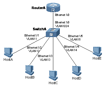
Figure 4-2 Network diagram for multicast VLAN configuration
III. Configuration procedure
1) Configuring Router A
# Enable IGMP and PIM-DM on Ethernet 1/0/1.
<RouterA> system-view
[RouterA] multicast routing-enable
[RouterA] interface ethernet 1/0/1
[RouterA-Ethernet1/0/1] pim dm
[RouterA-Ethernet1/0/1] igmp enable
2) Configuring Switch A
# Enable IGMP Snooping globally.
<SwitchA> system-view
[SwitchA] igmp-snooping
[SwitchA-igmp-snooping] quit
# Add Ethernet1/0/2 to VLAN11.
[SwitchA] vlan 11
[SwitchA-vlan11] port ethernet 1/0/2
[SwitchA-vlan11] quit
The configuration for VLAN12 through VLAN15 is similar to the configuration for VLAN11.
# Add Ethernet1/0/1 to VLAN1024 and enable IGMP Snooping in this VLAN.
[SwitchA] vlan 1024
[SwitchA-vlan1024] port Ethernet1/0/1
[SwitchA-vlan1024] igmp-snooping enable
[SwitchA-vlan1024] quit
# Configure VLAN1024 as multicast VLAN and configure VLAN11 through VLAN15 as its sub-VLANs.
[SwitchA] multicast-vlan 1024 enable
[SwitchA] multicast-vlan 1024 subvlan 11 to 15
3) Verify the configuration
# Display information about the multicast VLAN and its sub-VLANs.
[SwitchA] display multicast-vlan
multicast vlan 1024's subvlan list:
Vlan 11-15
Chapter 5 IGMP Configuration
5.1 IGMP Overview
As a TCP/IP protocol responsible for IP multicast group member management, the Internet Group Management Protocol (IGMP) is used by IP hosts to establish and maintain their multicast group memberships to immediately neighboring multicast routers.
5.1.1 IGMP Versions
So far, there are three IGMP versions:
l IGMPv1 (described in RFC 1112)
l IGMPv2 (described in RFC 2236)
l IGMPv3 (described in RFC 3376)
All IGMP versions support the Any-Source Multicast (ASM) model. In addition, IGMPv3 provides strong support to the Source-Specific Multicast (SSM) model.
5.1.2 Work Mechanism of IGMPv1
IGMPv1 manages multicast groups mainly based on the query and response mechanism.
Of multiple multicast routers on the same subnet, only one router is needed for sending IGMP queries because all the routers can receive IGMP reports from hosts. So, a querier election mechanism is required to determine which router will act as the IGMP querier on the subnet.
In IGMPv1, the designated router (DR) elected by the Layer 3 multicast routing protocol (such as PIM) serves as the IGMP querier.
For more information about a DR, refer to ” PIM Configuration”.
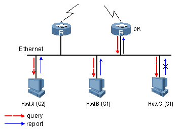
Figure 5-1 Work mechanism of IGMPv1
Assume that Host B and Host C are expected to receive multicasts address to multicast group G1, while Host A is expected to receive multicasts address to G2, as shown in Figure 5-1. The hosts join the multicast group in a process described below:
2) The IGMP querier (DR in the figure) periodically sends IGMP queries (with the destination address of 224.0.0.1) to all hosts and routers on the same subnet.
3) Upon receiving a query message, either Host B or Host C (the delay timer of whichever expires first), which is interested in the multicast data addressed to G1, sends an IGMP report first, with the destination address being the group address of G1, to announce that it will join G1. Assume it is Host B that sends the report message.
4) Because Host C is also interested in G1, it also receives the report that Host B sends to G1. Upon receiving the report, Host C will suppress itself from sending the same G1-specific message, because the IGMP routers already know that a host on the subnet is interested in G1. This IGMP report suppression mechanism helps reduce traffic over the local subnet.
5) Meanwhile, because Host A is interested in G2, it sends a report (with the group address of G2 as the destination address) to announce that it will join G2.
6) Through the query/report process, the IGMP routers learn about the receivers corresponding to G1 and G2 on the local subnet, and generate (*, G1) and (*, G2) multicast forwarding entries as the basis for forwarding the multicast information, where * represents any multicast source.
7) When the multicast data addressed to G1 or G2 reaches an IGMP router, because the (*, G1) and (*, G2) multicast forwarding entries exist on the IGMP router, the router forwards the data to the local subnet so that the receivers on the subnet can receive the data.
As IGMPv1 does not specifically define a Leave Group message, upon leaving a multicast group, an IGMPv1 host stops sending reports with the destination address being the address of that multicast group. If no member of a multicast group exists on the subnet, the IGMP routers will not receive any report addressed to that multicast report, so the routers will delete the forwarding entries corresponding to that multicast group.
5.1.3 Enhancements Provided by IGMPv2
Compared with IGMPv1, IGMPv2 provides the querier election mechanism and Leave Group mechanism.
I. Querier election mechanism
In IGMPv1, the DR elected by the Layer 3 multicast routing protocol (such as PIM) serves as the querier.
In IGMPv2, an independent querier election mechanism is introduced, The querier election process is as follows:
1) Initially, every IGMPv2 router assumes itself as the querier and sends IGMP general queries (with the destination address of 224.0.0.1) to all hosts and routers on the local subnet.
2) Then, every IGMPv2 router compares the source IP address of the received message with its own interface address. After comparison, the IGMPv2 router with the lowest IP address wins the querier election and all other IGMPv2 routers are non-queriers.
3) All the IGMP routers that have lost the querier election start a timer, namely the “other querier present interval”. If a router receives an IGMP query from the querier before the timer expires, it resets its timer; otherwise, it will assume the querier to have timed out and initiate a new querier election process.
II. “Leave group” mechanism
In IGMPv1, when a host leaves a multicast group, it does not send any notification to any multicast router. As a result, a multicast router relies on the response timeout to know that a member has left a group.
In IGMPv2, on the other hand, when a host leaves a multicast group:
1) This host sends a leave message to the all-system group (224.0.0.2) on the local subnet.
2) Upon receiving the leave message, the querier sends a group-specific query to the group that the host announced to leave.
3) Up receiving this group-specific query, each of the other members of that group, if any, will send a membership report within the maximum response time specified in the query.
4) If the querier receives a membership report sent by any member of the group within the maximum response time, it will maintain the memberships of that group; otherwise, the querier will assume that there is no longer any member of that group on the subnet and will stop maintaining the memberships of the group.
5.1.4 Enhancements Provided by IGMPv3
In addition to compatibility with the inheritance of IGMPv1 and IGMPv2, IGMPv3 provides hosts with enhanced control capabilities and provides enhancements of query and report messages.
I. Enhancements in control capability of hosts
IGMPv3 has introduced group- and source-specific filtering modes (Include and Exclude). As a result, a host can not only join a designated multicast group but also specify to receive or reject information from a designated multicast source.
l When a host joins a multicast group, if it needs to receive multicast information from specific sources like S1, S2, …, it sends a report with the Filter-Mode field set to “Include Sources (S1, S2, ……).
l When a host joins a multicast group, if it needs to reject multicast information from specific sources like S1, S2, …, it sends a report with the Filter-Mode field set to “Exclude Sources (S1, S2, ……).
As shown in Figure 5-2, the network comprises two multicast sources, Source 1 and Source 2, both of which can send multicast data to multicast group G. Host B is interested in only the multicast data that Source 1 sends to G and is not interested in the data from Source 2.
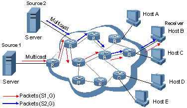
Figure 5-2 Flow paths of source-and-group-specific multicast traffic
If it is IGMPv1 or IGMPv2 that acts as the interaction protocol between the hosts and routers, Host B cannot select multicast sources when it joins the multicast group G. Therefore, multicasts from both Source1 and Source2 will go to Host B whether it needs them or not.
When IGMPv3 is running between the hosts and routers, Host B can request to join the multicast group G corresponding to Source 1, or request to leave the multicast group G corresponding to Source 2. Thus, only multicasts from Source 1 can reach Host B.
II. Enhancements in query and report capabilities
1) Query message carrying the source address
IGMPv3 supports not only general queries (feature of IGMPv1) and group-specific queries (feature of IGMPv2), but also group-and-source-specific queries.
l A general query does not carry a group address, nor a source addresses;
l A group-specific query carries a group address, but no source addresses;
l A group-and-source-specific query carries a group address and one or more source addresses.
2) Reports containing multiple group records
In IGMPv3, the destination address of a report is 224.0.0.22, and a report can contain one or more group records. Each group record contains a multicast group address and an uncertain number of source addresses.
Group record types include:
3) Current-state record: Sent in response to a query received on an interface, a current-state record reports the current reception state of that interface, which can be either of these two types: Include (the interface has a filter mode of Include for the specified multicast address list) and Exclude (the interface has a filter mode of Exclude for the specified multicast address list).
4) Filter-mode-change record: A filter-mode-change record indicates that the interface filter mode has changed from Include to Exclude or from Include to Exclude for the specified multicast address list.
5) Source-list-change record: A source-list-change record indicates that new source addresses are allowed or old source addresses are blocked.
5.1.5 Related Specifications
The following documents describe different IGMP versions:
l RFC 1112: Host Extensions for IP Multicasting
l RFC 2236: Internet Group Management Protocol, Version 2
l RFC 3376: Internet Group Management Protocol, Version 3
5.2 Configuring IGMP
Complete these tasks to configure IGMP:
|
Task |
Description |
|
|
Required |
||
|
Optional |
||
|
Optional |
||
|
Optional |
||
|
Optional |
||
& Note:
l Configurations performed in IGMP view are effective on all interfaces, while configurations performed in interface view are effective on the current interface only.
l If a feature is not configured for an interface in interface view, the global configuration performed in IGMP view will apply to that interface. If a feature is configured in both IGMP view and interface view, the configuration performed in interface view will be given priority.
5.3 Configuring Basic Functions of IGMP
5.3.1 Configuration Prerequisites
Before configuring the basic functions of IGMP, complete the following tasks:
l Configure any unicast routing protocol so that all devices in the domain are interoperable at the network layer.
l Configure PIM-DM or PIM-SM
Before configuring the basic functions of IGMP, prepare the following data:
l IGMP version
l Multicast group and multicast source addresses for static group member configuration
l ACL rule for multicast group filtering
5.3.2 Enabling IGMP
First, IGMP must be enabled on the interface on which the multicast group memberships are to be established and maintained.
Follow these steps to enable IGMP:
|
To do... |
Use the command... |
Description |
|
Enter system view |
system-view |
— |
|
Enable IP multicast routing |
multicast routing-enable |
Required Disabled by default |
|
Enter interface view |
interface interface-type interface-number |
— |
|
Enable IGMP |
igmp enable |
Required Disabled by default |
5.3.3 Configuring IGMP Versions
Because messages vary with different IGMP versions, the same IGMP version should be configured for all routers on the same subnet before IGMP can work properly.
I. Configuring an IGMP version globally
Follow these steps to configure an IGMP version globally:
|
To do... |
Use the command... |
Description |
|
Enter system view |
system-view |
— |
|
Enter IGMP view |
igmp |
— |
|
Configure an IGMP version globally |
version version-number |
Optional IGMPv2 by default |
II. Configuring an IGMP version for an interface
Follow these steps to configure an IGMP version on an interface:
|
To do... |
Use the command... |
Description |
|
Enter system view |
system-view |
— |
|
Enter interface view |
interface interface-type interface-number |
— |
|
Configure an IGMP version on the interface |
igmp version version-number |
Optional IGMPv2 by default |
5.4 Adjusting IGMP Performance
& Note:
For the configuration tasks described in this section:
l Configurations performed in IGMP view are effective on all interfaces, while configurations performed in interface view are effective on the current interface only.
l If the same feature or parameter is configured in both IGMP view and interface view, the configuration performed in interface view takes precedence, regardless of the configuration order of the two view.
5.4.1 Configuration Prerequisites
Before adjusting IGMP performance, complete the following tasks:
l Configure any unicast routing protocol so that all devices in the domain are interoperable at the network layer.
l Configure basic functions of IGMP
Before adjusting IGMP performance, prepare the following data:
l IGMP general query interval
l Maximum response time for IGMP general queries
l Other querier present interval
l IGMP last-member query interval and count
5.4.2 Configuring IGMP Message Options
Depending on whether an IGMP message carries the Router-Alert option in the IP header, the device processes the message differently. For details about Router-Alert, refer to RFC 2113.
By default, for the consideration of compatibility, the device does not check the Router-Alert option, namely it processes all the IGMP messages it received. In this case, IGMP messages are directly passed to the upper layer protocol, no matter whether the IGMP messages carry the Router-Alert option or not.
To enhance the device performance and avoid unnecessary costs, and also for the consideration of protocol security, you can configure the device to discard IGMP messages that do not carry the Router-Alert option.
I. Configuring IGMP packet options globally
Follow these steps to configure IGMP packet options globally:
|
To do... |
Use the command... |
Description |
|
Enter system view |
system-view |
— |
|
Enter IGMP view |
igmp |
— |
|
Configure the router to discard any IGMP message that does not carry the Router-Alert option |
require-router-alert |
Optional By default, the device does not check the Router-Alert |
|
Enable the insertion of the Router-Alert option into IGMP messages |
send-router-alert |
Optional By default, IGMP messages carry the Router-Alert option |
II. Configuring IGMP packet options for an interface
Follow these steps to configure IGMP packet options for an interface:
|
To do... |
Use the command... |
Description |
|
Enter system view |
system-view |
— |
|
Enter interface view |
interface interface-type interface-number |
— |
|
Configure the interface to discard any IGMP message that does not carry the Router-Alert option |
igmp require-router-alert |
Optional By default, the device does not check the Router-Alert |
|
Enable the insertion of the Router-Alert option into IGMP messages |
igmp send-router-alert |
Optional By default, IGMP messages carry the Router-Alert option |
5.4.3 Configuring IGMP Timers
The IGMP querier periodically sends IGMP general queries to decide whether any multicast group member exists on the network. You can tune the IGMP general query interval based on actual condition of the network.
Upon receiving an IGMP query (general query or group-specific query), a host starts a delay timer for each multicast group it has joined. This timer is initialized to a random value in the range of 0 to the maximum response time, which is derived from the Max Response Time field in the IGMP query. When the timer value comes down to 0, the host sends an IGMP report to the corresponding multicast group.
An appropriate setting of the maximum response time for IGMP queries allows hosts to respond to queries quickly and avoids burst of IGMP traffic on the network caused by reports simultaneously sent by a large number of hosts when corresponding timers expires simultaneously.
l For IGMP general queries, you can configure the maximum response time to fill their Max Response time field.
l For IGMP group-specific queries, you can configure the IGMP last-member query interval to fill their Max Response time field. Namely, for IGMP group-specific queries, the maximum response time equals the IGMP last-member query interval.
When multiple multicast routers exist on the same subnet, the IGMP querier is responsible for sending IGMP queries. If a non-querier router receives no IGMP query from the querier before the “other querier present interval” timer expires, it will assume the querier to have expired and a new querier election process is launched; otherwise, the non-querier router will reset its “other querier present interval” timer.
I. Configuring IGMP timers globally
Follow these steps to configure IGMP timers globally:
|
To do... |
Use the command... |
Description |
|
Enter system view |
system-view |
— |
|
Enter IGMP view |
igmp |
— |
|
Configure IGMP general query interval |
timer query interval |
Optional 60 seconds by default |
|
Configure the maximum response time for IGMP general queries |
max-response-time interval |
Optional 10 seconds by default |
|
Configure the IGMP last-member query interval |
lastmember-queryinterval interval |
Optional 1 second by default |
|
Configure the IGMP last-member query count |
robust-count robust-value |
Optional 2 times by default |
|
Configure the other querier present interval |
timer other-querier-present interval |
Optional For the system default, see “Note” below |
II. Configuring IGMP timers for an interface
Follow these steps to configure IGMP timers for an interface:
|
To do... |
Use the command... |
Description |
|
Enter system view |
system-view |
— |
|
Enter interface view |
interface interface-type interface-number |
— |
|
Configure IGMP general query interval |
igmp timer query interval |
Optional 60 seconds by default |
|
Configure the maximum response time for IGMP general queries |
igmp max-response-time interval |
Optional 10 seconds by default |
|
Configure the IGMP last-member query interval |
igmp lastmember-queryinterval interval |
Optional 1 second by default |
|
Configure the IGMP last-member query count |
igmp robust-count robust-value |
Optional 2 times by default |
|
Configure the other querier present interval |
igmp timer other-querier-present interval |
Optional For the system default, see “Note” below |
& Note:
l If not statically configured, the other querier present interval is (IGMP general query interval) times (IGMP last-member query count) plus (maximum response time to IGMP general queries) divided by 2. By default, the values of these three parameters are 60 (seconds), 2 (times) and 10 (seconds) respectively, so the default value of the other querier present interval = 60 × 2 + 10 ÷ 2 = 125 (seconds).
l If statically configured, the other querier present interval takes the configured value.
![]() Caution:
Caution:
l If the statically configured other querier present interval is shorter than the IGMP general query interval, the state of the querier may change frequently.
l In configuration, make sure that the maximum response time to IGMP general queries is less than the IGMP last-member query interval, namely the maximum response time to IGMP group-specific queries; otherwise, multicast group members may be wrongly removed.
l The configurations of the IGMP last-member query interval and count are effective only when the IGMP querier runs IGMPv2 or IGMPv3.
5.4.4 Configure IGMP Fast Leave
To enable fast response to leave messages of hosts, you can enable the IGMP fast leave feature.
With the fast leave function enabled, after an IGMP querier receives a Leave message from a host, it will no longer send an IGMP group specific query; instead, it will send a Leave notification to the upstream. As a result, the response delay is reduced on one hand, and the network bandwidth is saved on the other.
Follow these steps to enable IGMP fast leave globally:
|
To do... |
Use the command... |
Description |
|
Enter system view |
system-view |
— |
|
Enter IGMP view |
igmp |
— |
|
Enable IGMP fast leave |
prompt-leave [ group-policy acl-number ] |
Required Disabled by default |
5.5 Displaying and Maintaining IGMP
|
To do... |
Use the command... |
Description |
|
View IGMP multicast group information |
display igmp group [ group-address | interface interface-type interface-number ] [ static | verbose ] |
Available in any view |
|
View IGMP layer 2 port information |
display igmp group port-info [ vlan vlan-id ] [ verbose ] |
|
|
View IGMP configuration and running information |
display igmp interface [ interface-type interface-number ] [ verbose ] |
|
|
View routing information in the IGMP routing table |
display igmp routing-table [ source-address [ mask { mask | mask-length } ] | group-address [ mask { mask | mask-length } ] ] * |
|
|
Clear IGMP forwarding entries |
reset igmp group { all | interface interface-type interface-number { all | group-address [ mask { mask | mask-length } ] [ source-address [ mask { mask | mask-length } ] ] } } |
Available in user view |
& Note:
The reset igmp group command cannot clear the IGMP forwarding entries for static group members.
![]() Caution:
Caution:
The reset igmp group command may cause an interruption of receivers’ reception of multicast data.
5.6 IGMP Configuration Example
I. Network requirements
l Receivers receive VoD information through the multicast mode. Receivers of different organizations form stub networks, and one or more receiver hosts exist on each stub network.
l Host A and Host C are multicast receivers on two respective stub networks.
l Switch A on the PIM network is connected with one stub network, N1, and Switch B and Switch C are connected with another stub network, N2.
l Switch A is connected with N1 through Vlan-interface100, and with other devices on the PIM network through Vlan-interface101.
l Switch B and Switch C are connected with N2 through their own Vlan-interface200, and with other devices on the PIM network through Vlan-interface201 and Vlan-interface202 respectively.
l IGMPv3 runs between Switch A and N1. IGMPv2 runs between (Switch B and Switch C) and N2, where Switch B acts as the IGMP querier.
II. Network diagram

Figure 5-3 Network diagram for IGMP configuration
III. Configuration procedure
1) Configure the IP addresses of the switch interfaces and a unicast routing protocol.
Configure the IP address and subnet mask of each interface as per Figure 5-3. The detailed configuration steps are omitted here.
Configure the OSPF protocol for interoperation among the switches. Ensure the network-layer interoperation among Switch A, Switch B and Switch C on the PIM network and dynamic update of routing information among the switches through a unicast routing protocol. The detailed configuration steps are omitted here.
2) Enable IP multicast routing, and enable IGMP on the host-side interfaces.
# Enable IP multicast routing on Switch A, and enable IGMP (version 3) and PIM-DM on Vlan-interface100.
<SwitchA> system-view
[SwitchA] multicast routing-enable
[SwitchA] interface vlan-interface 100
[SwitchA-Vlan-interface100] igmp enable
[SwitchA-Vlan-interface100] igmp version 3
[SwitchA-Vlan-interface100] pim dm
[SwitchA-Vlan-interface100] quit
# Enable IP multicast routing on Switch B, and enable IGMP (version 2) and PIM-DM on Vlan-interface200.
<SwitchB> system-view
[SwitchB] multicast routing-enable
[SwitchB] interface vlan-interface 200
[SwitchB-Vlan-interface200] igmp enable
[SwitchB-Vlan-interface200] igmp version 2
[SwitchB-Vlan-interface200] pim dm
[SwitchB-Vlan-interface200] quit
# Enable IP multicast routing on Switch C, and enable IGMP (version 2) and PIM-DM on Vlan-interface200.
<SwitchC> system-view
[SwitchC] multicast routing-enable
[SwitchC] interface vlan-interface 200
[SwitchC-Vlan-interface200] igmp enable
[SwitchC-Vlan-interface200] igmp version 2
[SwitchC-Vlan-interface200] pim dm
[SwitchC-Vlan-interface200] quit
3) Verifying the configuration
Carry out the display igmp interface command to view the IGMP configuration and running status on each switch interface. For example:
# View IGMP information on Vlan-interface200 of Switch B.
[SwitchB] display igmp interface vlan-interface 200
Vlan-interface200(10.110.2.1):
IGMP is enabled
Current IGMP version is 2
Value of query interval for IGMP(in seconds): 60
Value of other querier timeout for IGMP(in seconds): 125
Value of maximum query response time for IGMP(in seconds): 10
Querier for IGMP: 10.110.2.1 (this router)
Total 1 IGMP Group reported
5.7 Troubleshooting IGMP
5.7.1 No Multicast Group Member Information on the Receiver-Side Router
I. Symptom
When a host sends a report for joining multicast group G, there is no member information of the multicast group G on the router closest to that host.
II. Analysis
l The correctness of networking and interface connections directly affects the generation of group member information.
l Multicast routing must be enabled on the router.
III. Solution
1) Check that the networking is correct and interface connections are correct.
2) Check that the interfaces and the host are on the same subnet. Use the display current-configuration interface command to view the IP addresses of the interfaces.
3) Check that multicast routing is enabled. Carry out the display current-configuration command to check whether the multicast routing-enable command has been executed. If not, carry out the multicast routing-enable command in system view to enable IP multicast routing. In addition, check that IGMP is enabled on the corresponding interfaces.
4) Check that the interface is in normal state and the correct IP address has been configured. Carry out the display igmp interface command to view the interface information. If no interface information is output, this means the interface is abnormal. Typically this is because the shutdown command has been executed on the interface, or the interface connection is incorrect, or no correct IP address has been configured on the interface.
5.7.2 Inconsistent Memberships on Routers on the Same Subnet
I. Symptom
Different memberships are maintained on different IGMP routers on the same subnet.
II. Analysis
l A router running IGMP maintains multiple parameters for each interface, and these parameters influence one another, forming very complicated relationships. Inconsistent IGMP interface parameter configurations for routers on the same subnet will surely result in inconsistency of memberships.
l In addition, although IGMP routers are compatible with hosts, all routers on the same subnet must run the same version of IGMP. Inconsistent IGMP versions running on routers on the same subnet will also lead to inconsistency of IGMP memberships.
III. Solution
1) Check the IGMP configuration. Carry out the display current-configuration command to view the IGMP configuration information on the interfaces.
2) Carry out the display igmp interface command on all routers on the same subnet to check the IGMP-related timer settings. Make sure that the settings are consistent on all the routers.
3) Use the display igmp interface command to check whether the routers are running the same version of IGMP.
Chapter 6 PIM Configuration
6.1 PIM Overview
Protocol Independent Multicast (PIM) provides IP multicast forwarding by leveraging static routes or unicast routing tables generated by any unicast routing protocol, such as routing information protocol (RIP), open shortest path first (OSPF), intermediate system to intermediate system (IS-IS), or border gateway protocol (BGP). PIM uses a unicast routing table to perform reverse path forwarding (RPF) check to implement multicast forwarding. For more information about RPF, refer to ” RPF mechanism”.
Based on the forwarding mechanism, PIM falls into two modes:
l Protocol Independent Multicast–Dense Mode (PIM-DM), and
l Protocol Independent Multicast–Sparse Mode (PIM-SM).
& Note:
To facilitate description, a network comprising PIM-capable routers is referred to as a “PIM domain” in this document.
6.1.1 Introduction to PIM-DM
PIM-DM is a type of dense mode multicast protocol. It uses the “push mode” for multicast forwarding, and is suitable for small-sized networks with densely distributed multicast members.
PIM-DM has the following features:
l PIM-DM assumes that at least one multicast group member exists on each subnet of a network, and therefore multicast data is flooded to all nodes on the network. Then, branches without multicast forwarding are pruned from the forwarding tree, leaving only those branches that contain receivers. This “flood and prune” process takes place periodically, that is, pruned branches resume multicast forwarding when the pruned state times out and then data is re-flooded down these branches, and then are pruned again.
l When a new receiver on a previously pruned branch joins a multicast group, to reduce the join latency, PIM-DM uses a graft mechanism to resume data forwarding to that branch.
Generally speaking, the multicast forwarding path is a source tree, namely a forwarding tree with the multicast source as its “root” and multicast group members as its “leaves”. Because the source tree is the shortest path from the multicast source to the receivers, it is also called shortest path tree (SPT).
6.1.2 How PIM-DM Works
The working mechanism of PIM-DM is summarized as follows:
l Neighbor discovery
l SPT building
l Graft
I. Neighbor discovery
In a PIM domain, a router discovers PIM neighbors and maintains PIM neighboring relationships with other routers by multicasting hello messages to all PIM routers (224.0.0.13).
Every activated interface on a router sends hello messages periodically, and thus learns the PIM neighboring information pertinent to the interface.
II. SPT building
The process of building an SPT is the process of “flood and prune”.
1) In a PIM-DM domain, when a multicast source S sends multicast data to a multicast group G, the multicast packet is first flooded throughout the domain: The router first performs RPF check on the multicast packet. If the packet passes the RPF check, the router creates an (S, G) entry and forwards the data to all downstream nodes in the network. In the flooding process, an (S, G) entry is created on all the routers in the PIM-DM domain.
2) Then, nodes without downstream receivers are pruned: A router having no down stream receivers sends a prune message to the upstream node to notify the upstream node to delete the corresponding interface from the outgoing interface list (OIL) in the (S, G) entry and stop forwarding subsequent packets addressed to that multicast group down to this node.
& Note:
An (S, G) entry contains the multicast source address S, multicast group address G, OIL, and incoming interface.
As shown in Figure 6-1, the pruning process is first initiated by a leaf router (Router A, for example), and this process goes on until only necessary branches are left in the PIM-DM domain. These branches constitute the SPT.
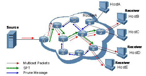
The “flood and prune” process takes place periodically. A pruned state timeout mechanism is provided. A pruned branch restarts multicast forwarding when the pruned state times out and then is pruned again when it no longer has any multicast receiver.
III. Graft
When a new receiver on a previously pruned branch joins a multicast group, to reduce the join latency, PIM-DM uses a graft mechanism to resume data forwarding to that branch. The process is as follows:
1) When a node on a previously pruned branch needs to resume multicast receiving, it sends a graft message up the distribution tree toward the source, as a request to join the SPT again.
2) Upon receiving this graft message, the upstream PIM DM device immediately puts the interface on which the graft was received into the forwarding state so that the multicast traffic starts flowing to the receiver, and responds with a graft-ack message to the graft sender.
IV. Assert
If multiple multicast routers exist on a multi-access subnet, duplicate packets may flow to the same subnet. To shutoff duplicate flows, the assert mechanism is used for election of a single multicast forwarder on a multi-access network.
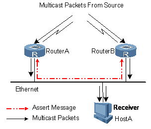
As shown in Figure 6-2, after multicast Router A and Router B on a multi-access subnet receive an (S, G) packet from the upstream, they both forward the packet to the local subnet. As a result, each of these two routers receives a duplicate packet forwarded by the other. Upon detecting this condition, both routers send an assert message to all PIM routers (224.0.0.13) through the interface on which the packet was received. The assert message contains the following information: the multicast source address (S), the multicast group address (G), and the preference and metric of the unicast route to the source. By comparing these parameters, Router A or Router B becomes the single forwarder of the (S, G) packet on the multi-access subnet. The comparison process is as follows:
1) The router with a higher unicast route preference to the source wins;
2) If both routers have the same unicast route preference to the source, the router with a smaller metric to the source wins;
3) If there is a tie in route metric to the source, the router with a higher IP address of the local interface wins.
6.1.3 Introduction to PIM-SM
PIM-DM uses the “flood and prune” principle to build SPTs for multicast data distribution. Although an SPT has the shortest path, it is built with a low efficiency. Therefore the PIM-DM mod is not suitable for large- and medium-sized networks.
PIM-SM is a type of sparse mode multicast protocol. It uses the “pull mode” for multicast forwarding, and is suitable for large- and medium-sized networks with sparsely and widely distributed multicast group members.
PIM-SM has the following features:
l PIM-SM assumes that no hosts need to receive multicast data. In the PIM-SM mode, routers must specifically request a particular multicast stream before the data is forwarded to them. The core task for PIM-SM to implement multicast forwarding is to build and maintain rendezvous point trees (RPTs). An RPT is rooted at a router in the PIM domain as the common node, or rendezvous point (RP), through which the multicast data travels along the RPT and reaches the receivers.
l When a receiver is interested in the multicast data addressed to a specific multicast group, the router connected to this receiver sends a join message to the RP corresponding to that multicast group. The path along which the message goes hop by hop to the RP forms a branch of the RPT.
l When a multicast source sends a multicast packet to a multicast group, the router directly connected with the multicast source first encapsulates the packet in a register message, and sends the message to the corresponding RP by unicast. The arrival of this message at the RP triggers the establishment of an SPT. Then, the multicast source sends the multicast packet along the SPT to the RP. Upon reaching the RP, the multicast packet is duplicated and delivered to the receivers along the RPT.
6.1.4 How PIM-SM Works
The working mechanism of PIM-SM is summarized as follows:
l Neighbor discovery
l DR election
l RP discovery
l RPT building
l Multicast source registration
l Switchover from RPT to SPT
l Assert
I. Neighbor discovery
PIM-SM uses exactly the same neighbor discovery mechanism as PIM-DM does. Refer to “Neighbor discovery”.
II. DR election
PIM-SM also uses hello messages to elect a designated router (DR) for a multi-access network. The elected DR will be the only multicast forwarder on this multi-access network.
A DR must be elected for a multi-access network, no matter this network connects to multicast sources or to receivers. The DR at the receiver side sends join messages to the RP; the DR at the multicast source side sends register messages to the RP.
& Note:
An elected DR is substantially meaningful to PIM-SM. PIM-DM itself does not require a DR. However, if IGMPv1 runs on any multi-access network in a PIM-DM domain, a DR must be elected to act as the IGMPv1 querier on that multi-access network.
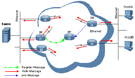
As shown in Figure 6-3, the DR election process is as follows:
1) Routers on the multi-access network send hello messages to one another. The hello messages contain the router priority for DR election. The router with the highest DR priority will become the DR.
2) In the case of a tie in the router priority, or if any router in the network does not support carrying the DR-election priority in hello messages, The router with the highest IP address will win the DR election.
When the DR works abnormally, a timeout in receiving hello message triggers a new DR election process among the other routers.
III. RP discovery
The RP is the core of a PIM-SM domain. For a small-sized, simple network, one RP is enough for forwarding information throughout the network, and the position of the RP can be statically specified on each router in the PIM-SM domain. In most cases, however, a PIM-SM network covers a wide area and a huge amount of multicast traffic needs to be forwarded through the RP. To lessen the RP burden and optimize the topological structure of the RPT, each multicast group should have its own RP. Therefore, a bootstrap mechanism is needed for dynamic RP election. For this purpose, a bootstrap router (BSR) should be configured.
As the administrative core of a PIM-SM domain, the BSR collects advertisement messages (C-RP-Adv messages) from candidate-RPs (C-RPs) and chooses the appropriate C-RP information for each multicast group to form an RP-Set, which is a database of mappings between multicast groups and RPs. The BSR then floods the RP-Set to the entire PIM-SM domain. In this way, all routers (including the DRs) in the network know where the RP is.
A PIM-SM domain (or an administratively scoped region) can have only one BSR, but can have multiple candidate-BSRs (C-BSRs). Once the BSR fails, a new BSR is automatically elected from the C-BSRs through the bootstrap mechanism to avoid service interruption. Similarly, multiple C-RPs can be configured in a PIM-SM domain, and the position of the RP corresponding to each multicast group is calculated through the BSR mechanism.
Figure 6-4 shows the positions of C-RPs and the BSR in the network.
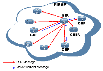
IV. RPT building
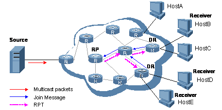
As shown in Figure 6-5, the process of building an RPT is as follows:
1) When a receiver joins a multicast group G, it uses an IGMP message to inform the directly connected DR.
2) Upon getting the receiver information, the DR sends a join message, which is hop by hop forwarded to the RP.
3) The routers along the path from the DR to the RP form an RPT branch. Each router on this branch generates a (*, G) entry in its forwarding table. The * means any multicast source. The RP is the root, while the DRs are the leaves, of the RPT.
The multicast data addressed to the multicast group G flows through the RP, reaches the corresponding DR along the established RPT, and finally is delivered to the receiver.
When a receiver is no longer interested in the multicast data addressed to a multicast group G, the directly connected DR sends a prune message, which goes hop by hop along the RPT to the RP. Upon receiving the prune message, the upstream router deletes its link with this downstream router from the OIL and checks whether it itself has receivers for that multicast group. If not, the router continues to forward the prune message to its upstream router.
V. Multicast source registration
The purpose of multicast source registration is to inform the RP about the existence of the multicast source.
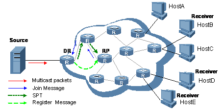
Figure 6-6 SPT establishment in a PIM-SM domain
As shown in Figure 6-6, the multicast source registers with the RP as follows:
2) When the multicast source S sends a packet to a multicast group G, the DR directly connected with the multicast source, upon receiving the packet, encapsulates the packet in a PIM register message, and sends the packet to the corresponding RP by unicast.
3) When the RP receives the register message, on one hand, it decapsulates the register message and forwards the packet to the receivers along the RPT, and, on the other hand, it sends an (S, G) join message hop by hop to the multicast source. Thus, the routers along the path from the RP to the multicast source constitute an SPT branch. Each router on this branch generates a (S, G) entry in its forwarding table. The multicast source is the root, while the RP is the leaf, of the SPT.
The multicast data from the multicast source reaches the RP along the established SPT, and then the RP forwards the data along the RPT to the receivers.
VI. Switchover from RPT to SPT
When the receiver-side DR finds that the traffic rate of the multicast packets the RP sends to a multicast group G exceeds a configurable threshold, the RP will initiate an RPT-to-SPT switchover process, as follows:
1) First, the receiver-side DR sends an (S, G) join message hop by hop to the multicast source. When the join message reaches the source-side DR, all the routers on the path have installed the (S, G) entry in their forwarding table, and thus an SPT branch is established.
2) Subsequently, the receiver-side DR sends a prune message hop by hop to the RP. Upon receiving this prune message, the RP forwards it towards the multicast source, thus to implement RPT-to-SPT switchover.
After the RPT-to-SPT switchover, multicast data can be directly sent from the source to the receivers. PIM-SM builds SPTs through RPT-to-SPT switchover more economically than PIM-DM does through the “flood and prune” mechanism.
VII. Assert
PIM-SM uses exactly the same assert mechanism as PIM-DM does. Refer to “Assert”.
6.1.5 Introduction to BSR Admin-scope Regions in PIM-SM
I. Division of PIM-SM domains
Typically, a PIM-SM domain contains only one BSR, which is responsible for advertising RP-Set information throughout the entire PIM-SM domain. The information for all multicast groups is forwarded within the network scope administered by the BSR.
To implement refined management and group-specific services, a PIM-SM domain can be divided into one global scope zone and multiple BSR administratively scoped regions (BSR admin-scope regions).
II. Relationship between BSR admin-scope regions and the global scope zone
A better understanding of the global scope zone and BSR admin-scope regions should be based on two aspects: geographical space and group address range.
1) Geographical space
BSR admin-scope regions are logical regions specific to particular multicast groups, and each BSR admin-scope region must be geographically independent of another, as shown in Figure 6-7.
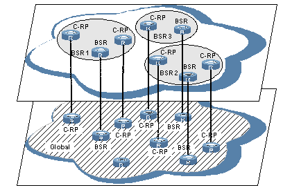
Figure 6-7 Relationship between BSR admin-scope regions in geographic space
BSR admin-scope regions are geographically segregated from one another. Namely, a router must not serve different BSR admin-scope regions. In other words, different BSR admin-scope regions contain different routers, whereas the global scope zone covers all routers in the PIM-SM domain.
2) In terms of multicast group address ranges
Each BSR admin-scope region serves specific multicast groups. Usually, these addresses have no intersections, however, they may overlap one another, as shown in Figure 6-8.
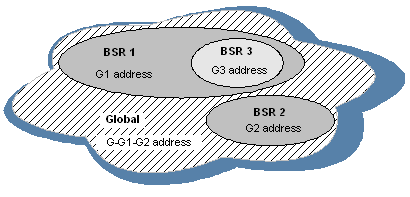
Figure 6-8 Relationship between BSR admin-scope regions in group address ranges
In Figure 6-8, the group address ranges of admin-scope-scope regions BSR1 and BSR2 have no intersection, whereas the group address range of BSR3 is a subset of the address range of BSR1. The group address range of the global scope zone covers all the group addresses other than those of all the BSR admin-scope regions. That is, the group address range of the global scope zone is G-G1-G2. In other words, there is a supplementary relationship between the global scope zone and all the BSR admin-scope regions in terms of group address ranges.
Relationships between BSR admin-scope regions and the global scope zone are as follows:
l The global scope zone and each BSR admin-scope region have their own C-RPs and BSR. These devices are effective only in their respective admin-scope regions. Namely, the BSR election and RP election are implemented independently within each admin-scope region.
l Each BSR admin-scope region has its own boundary. The multicast information (such as C-RP-Adv messages and BSR bootstrap messages) can be transmitted only within the domain.
l Likewise, the multicast information in the global scope zone cannot enter any BSR admin-cope region.
l In terms of multicast information propagation, BSR admin-scope regions are independent of one another and each BSR admin-scope region is independent of the global scope zone, and no overlapping is allowed between any two BSR admin-scope regions.
6.1.6 SSM Model Implementation in PIM
The source-specific multicast (SSM) model and the any-source multicast (ASM) model are two opposite models. Presently, the ASM model includes the PIM-DM and PIM-SM modes. The SSM model can be implemented by leveraging part of the PIM-SM technique.
The SSM model provides a solution for source-specific multicast. It maintains the relationships between hosts and routers through IGMPv3. PIM-DM implements multicast forwarding by building SPTs rooted at the multicast source through the “flood and prune” mechanism. Although an SPT has the shortest path, it is built in a low efficiency. Therefore the PIM-DM mod is not suitable for large- and medium-sized networks.
In actual application, part of the PIM-SM technique is adopted to implement the SSM model. In the SSM model, receivers know exactly where a multicast source is located by means of advertisements, consultancy and so on. Therefore, no RP is needed, no RPT is required, there is no source registration process, and there is no need of using the multicast source discovery protocol (MSDP) for discovering sources in other PIM domains.
The SSM model only needs the support of IGMPv3 and some subsets of PIM-SM. The operation mechanism of PIM-SSM can be summarized as follows:
l Neighbor discovery
l DR election
l SPT building
I. Neighbor discovery and DR election
PIM-SSM uses the same neighbor discovery mechanism as in PIM-DM and PIM-SM, and the same DR election mechanism as in PIM-SM. Refer to “Neighbor discovery” and “DR election”.
II. Construction of SPT
Whether to build an RPT for PIM-SM or an SPT for PIM-SSM depends on whether the multicast group the receiver is to join falls in the SSM group address range (SSM group address range reserved by IANA is 232.0.0.0/24).
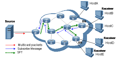
Figure 6-9 SPT establishment in PIM-SSM
As shown in Figure 6-9, Hosts B, D and E are multicast information receivers. They send an IGMPv3 report message marked (Include S, G) to the respective DRs to indicate that they are interested in the information of the specific multicast source S. If they need information from other sources than S, they send an (Exclude S, G) report. No matter what the description is, the position of multicast source S is explicitly specified for receivers.
The DR that has received the report first checks whether the group address in this message falls in the SSM group address range:
l If so, the DR sends a subscribe message for channel subscription hop by hop toward the multicast source S. An (Include S, G) or (Exclude S, G) entry is created on all routers on the path from the DR to the source. Thus, an SPT is built in the network, with the source S as its root and receivers as its leaves. This SPT is the transmission channel in PIM-SSM.
l If not, the PIM-SM process is followed: the DR needs to send a join message to the RP, and a multicast source registration process is needed.
& Note:
In PIM-SSM, the “channel” concept is used to refer to a multicast group, and the “channel subscription” concept is used to refer to a join message.
6.1.7 Related Specifications
PIM-related specifications are as follows:
l RFC 2362: Protocol Independent Multicast-sparse Mode (PIM-SM): Protocol Specification
l RFC 3973: Protocol Independent Multicast-Dense Mode (PIM-DM): Protocol Specification(Revised)
l draft-ietf-pim-sm-v2-new-07: Protocol Independent Multicast-Sparse Mode (PIM-SM)
l draft-ietf-pim-dm-new-v2-05: Protocol Independent Multicast-Dense Mode (PIM-DM)
l draft-ietf-pim-v2-dm-03: Protocol Independent Multicast Version 2 Dense Mode Specification
l draft-ietf-pim-sm-bsr-03: Bootstrap Router (BSR) Mechanism for PIM Sparse Mode
l draft-ietf-ssm-arch-03: Source-Specific Multicast for IP
l draft-ietf-ssm-overview-05: An Overview of Source-Specific Multicast (SSM)
6.2 Configuring PIM-DM
6.2.1 PIM-DM Configuration Tasks
Complete these tasks to configure PIM-DM:
|
Task |
Remarks |
|
Required |
|
|
Optional |
|
|
Optional |
|
|
Optional |
|
|
Optional |
6.2.2 Configuration Prerequisites
Before configuring PIM-DM, complete the following task:
l Configure any unicast routing protocol so that all devices in the domain are interoperable at the network layer.
Before configuring PIM-DM, prepare the following data:
l The interval between state refresh messages
l Minimum time to wait before receiving a new refresh message
l TTL value of state refresh messages
6.2.3 Enabling PIM-DM
With PIM-DM enabled, a router sends hello messages periodically to discover PIM neighbors and processes messages from PIM neighbors. When deploying a PIM-DM domain, you are recommended to enable PIM-DM on all interfaces of non-border routers (border routers are PIM-enabled routers located on the boundary of BSR admin-scope regions).
Follow these steps to enable PIM-DM:
|
To do... |
Use the command... |
Remarks |
|
Enter system view |
system-view |
— |
|
Enable IP multicast routing |
multicast routing-enable |
Required Disable by default |
|
Enter interface view |
interface interface-type interface-number |
— |
|
Enable PIM-DM |
pim dm |
Required Disabled by default |
![]() Caution:
Caution:
All the interfaces of the same router must work in the same PIM mode.
6.2.4 Enabling State Refresh
An interface without the state refresh capability cannot forward state refresh messages.
Follow these steps to enable the state refresh capability:
|
To do... |
Use the command... |
Remarks |
|
Enter system view |
system-view |
— |
|
Enter interface view |
interface interface-type interface-number |
— |
|
Enable state refresh |
pim state-refresh-capable |
Optional Enabled by default |
6.2.5 Configuring State Refresh Parameters
To avoid the resource-consuming reflooding of unwanted traffic caused by timeout of pruned interfaces, the router directly connected with the multicast source periodically sends an (S, G) state refresh message, which is forwarded hop by hop along the initial multicast flooding path of the PIM-DM domain, to refresh the prune timer state of all the routers on the path.
A router may receive multiple state refresh messages within a short time, of which some may be duplicated messages. To keep a router from receiving such duplicated messages, you can configure the time the router must wait before receiving the next state refresh message. If a new state refresh message is received within the waiting time, the router will discard it; if this timer times out, the router will accept a new state refresh message, refresh its own PIM state, and reset the waiting timer.
The TTL value of a state refresh message decrements by 1 whenever it passes a router before it is forwarded to the downstream node until the TTL value comes down to 0. In a small network, a state refresh message may cycle in the network. To effectively control the propagation scope of state refresh messages, you need to configure an appropriate TTL value based on the network size.
Follow these steps to configure state refresh parameters:
|
To do... |
Use the command... |
Remarks |
|
Enter system view |
system-view |
— |
|
Enter PIM view |
pim |
— |
|
Configure the interval between state refresh messages |
state-refresh-interval interval |
Optional 60 seconds by default |
|
Configure the time to wait before receiving a new state refresh message |
state-refresh-rate-limit interval |
Optional 30 seconds by default |
|
Configure the TTL value of state refresh messages |
state-refresh-ttl ttl-value |
Optional 255 by default |
6.2.6 Configuring PIM-DM Graft Retry Period
In PIM-DM, graft is the only type of message that uses the acknowledgment mechanism. In a PIM-DM domain, if a router does not receive a graft-ack message from the upstream router within the specified time after it sends a graft message, the router keeps sending new graft messages at a configurable interval, namely graft retry period, until it receives a graft-ack from the upstream router.
Follow these steps to configure graft retry period:
|
To do... |
Use the command... |
Remarks |
|
Enter system view |
system-view |
— |
|
Enter interface view |
interface interface-type interface-number |
— |
|
Configure graft retry period |
pim timer graft-retry interval |
Optional 3 seconds by default |
& Note:
For the configuration of other timers in PIM-DM, refer to “Configuring PIM Common Timers”
6.3 Configuring PIM-SM
& Note:
A device can serve as a C-RP and a C-BSR at the same time.
6.3.1 PIM-SM Configuration Tasks
Complete these tasks to configure PIM-SM:
|
Task |
Remarks |
|
|
Required |
||
|
Optional |
||
|
Optional |
||
|
Optional |
||
|
Optional |
||
|
Optional |
||
|
Optional |
||
|
Optional |
||
|
Optional |
||
|
Optional |
||
|
Optional |
||
|
Optional |
||
|
Optional |
||
6.3.2 Configuration Prerequisites
Before configuring PIM-SM, complete the following task:
l Configure any unicast routing protocol so that all devices in the domain are interoperable at the network layer.
Before configuring PIM-SM, prepare the following data:
l An ACL rule defining a legal BSR address range
l Hash mask length for RP selection calculation
l C-BSR priority
l Bootstrap interval
l Bootstrap timeout time
l An ACL rule defining a legal C-RP address range and the range of multicast groups to be served
l C-RP-Adv interval
l C-RP timeout time
l The IP address of a static RP
l An ACL rule for register message filtering
l Register suppression timeout time
l Probe time
l The multicast traffic rate threshold, ACL rule, and sequencing rule for RPT-to-SPT switchover
l The interval of checking the traffic rate threshold before RPT-to-SPT switchover
6.3.3 Enabling PIM-SM
With PIM-SM enabled, a router sends hello messages periodically to discover PIM neighbors and processes messages from PIM neighbors. When deploying a PIM-SM domain, you are recommended to enable PIM-SM on all interfaces of non-border routers (border routers are PIM-enabled routers located on the boundary of BSR admin-scope regions).
Follow these steps to enable PIM-SM:
|
To do... |
Use the command... |
Remarks |
|
Enter system view |
system-view |
— |
|
Enable IP multicast routing |
multicast routing-enable |
Required Disable by default |
|
Enter interface view |
interface interface-type interface-number |
— |
|
Enable PIM-SM |
pim sm |
Required Disabled by default |
![]() Caution:
Caution:
All the interfaces of the same router must work in the same PIM mode.
6.3.4 Configuring a BSR
& Note:
The BSR is dynamically elected from a number of C-BSRs. Because it is unpredictable which router will finally win a BSR election, the commands introduced in this section must be configured on all C-BSRs.
About the Hash mask length and C-BSR priority for RP selection calculation:
l You can configure these parameters at three levels: global configuration level, global scope level, and BSR admin-scope level.
l By default, the global scope parameters and BSR admin-scope parameters are those configured at the global configuration level.
l Parameters configured at the global scope level or BSR admin-scope level have higher priority than those configured at the global configuration level.
I. Performing basic C-BSR configuration
A PIM-SM domain can have only one BSR, but must have at least one C-BSR. Any router can be configured as C-BSR. Elected from C-BSRs, a BSR is responsible for collecting and advertising RP information in the PIM-SM.
C-BSRs should be configured on routers in the backbone network. When configuring a router as a C-BSR, be sure to specify a PIM-SM-enabled. The BSR election process is as follows:
l Initially, every C-BSR assumes itself to be the BSR of this PIM-SM domain, and uses its interface IP address as the BSR address to send bootstrap messages.
l When a C-BSR receives the bootstrap message of another C-BSR, it first compares its own priority with the other C-BSR’s priority carried in the message. The C-BSR with a higher priority wins. If there is a tie in the priority, the C-BSR with a higher IP address wins. The loser uses the winner’s BSR address to replace its own BSR address and no longer assumes itself to be the BSR, while the winner keeps its own BSR address and continues assuming itself to be the BSR.
Configuring a legal range of BSR addresses enables filtering of BSR messages based on the address range, thus to prevent malicious hosts from initiating attacks by disguising themselves as legitimate BSRs. To protect legitimate BSRs from being maliciously replaced, preventive measures are taken specific to the following two situations:
1) Some malicious hosts intend to fool routers by forging BSR messages and change the RP mapping relationship. Such attacks often occur on border routers. Because a BSR is inside the network whereas hosts are outside the network, you can protect a BSR against attacks from external hosts by enabling border routers to perform neighbor check and RPF check on BSR messages and discard unwanted messages.
2) When a router in the network is controlled by an attacker or when an illegal router is present in the network, the attacker can configure such a router to be a C-BSR and make it win BSR election so as to gain the right of advertising RP information in the network. After being configured as a C-BSR, a router automatically floods the network with BSR messages. As a BSR message has a TTL value of 1, the whole network will not be affected as long as the neighbor router discards these BSR messages. Therefore, if a legal BSR address range is configured on all routers in the entire network, all routers will discard BSR messages from out of the legal address range, and thus this kind of attacks can be prevented.
The above-mentioned preventive measures can partially protect the security of BSRs in a network. However, if a legal BSR is controlled by an attacker, the above-mentioned problem will also occur.
Follow these steps to complete basic C-BSR configuration:
|
To do... |
Use the command... |
Remarks |
|
Enter system view |
system-view |
— |
|
Enter PIM view |
pim |
— |
|
Configure an interface as a C-BSR |
c-bsr interface-type interface-number [ hash-length [ priority ] ] |
Required No C-BSR is configured by default |
|
Configure a legal BSR address range |
bsr-policy acl-number |
Optional No restrictions on BSR address range by default |
& Note:
Since a large amount of information needs to be exchanged between a BSR and the other devices in the PIM-SM domain, a relatively large bandwidth should be provided between the C-BSR and the other devices in the PIM-SM domain.
II. Configuring a global-scope C-BSR
Follow these steps to configure a global-scope C-BSR:
|
To do... |
Use the command... |
Remarks |
|
Enter system view |
system-view |
— |
|
Enter PIM view |
pim |
— |
|
Configure a global-scope C-BSR |
c-bsr global [ hash-length hash-length | priority priority ] * |
Required No global-scope C-BSRs by default |
III. Configuring an admin-scope C-BSR
To manage your network more effectively and specially, you can enable the BSR administrative scoping mechanism on all routers in the PIM-SM domain.
Specific to particular multicast groups, the BSR administrative scoping mechanism makes it possible to effectively lessen the management workload of a single-BSR domain and provide group-specific services.
Follow these steps to configure a admin-scope C-BSR:
|
To do... |
Use the command... |
Remarks |
|
Enter system view |
system-view |
— |
|
Enter PIM view |
pim |
— |
|
Enable BSR administrative scoping |
c-bsr admin-scope |
Required Disabled by default |
|
Configure an admin-scope C-BSR |
c-bsr group group-address { mask | mask-length } [ hash-length hash-length | priority priority ] * |
Optional No admin-scope BSRs by default |
IV. Configuring a BSR admin-scope region boundary
A BSR has its specific service scope. A number of BSR boundary interfaces divide a network into different BSR admin-scope regions. Bootstrap messages cannot cross the admin-scope region boundary, while other types of PIM messages can.
Follow these steps to configure a BSR admin-scope region boundary:
|
To do... |
Use the command... |
Remarks |
|
Enter system view |
system-view |
— |
|
Enter interface view |
interface interface-type interface-number |
— |
|
Configure a BSR admin-scope region boundary |
pim bsr-boundary |
Required No BSR admin-scope region boundary by default |
V. Configuring global C-BSR parameters
The BSR election winner advertises its own IP address and RP-Set information throughout the region it serves through bootstrap messages. The BSR floods bootstrap messages throughout the network periodically. Any C-BSR that receives a bootstrap message maintains the BSR state for a configurable period of time (BSR state timeout), during which no BSR election takes place. When the BSR state times out, a new BSR election process will be triggered among the C-BSRs.
Follow these steps to global C-BSR parameters:
|
To do... |
Use the command... |
Remarks |
|
Enter system view |
system-view |
— |
|
Enter PIM view |
pim |
— |
|
Configure the Hash mask length for RP selection calculation |
c-bsr hash-length hash-length |
Optional 30 by default |
|
Configure the C-BSR priority |
c-bsr priority priority |
Optional 0 by default |
|
Configure the bootstrap interval |
c-bsr interval interval |
Optional For the system default, see “Note” below. |
|
Configure the bootstrap timeout time |
c-bsr holdtime interval |
Optional |
& Note:
About the bootstrap timeout time:
l By default, the bootstrap timeout value is determined by this formula: The default bootstrap interval is 60 seconds, so the default bootstrap timeout = 60 × 2 + 10 = 130 (seconds).
l If this parameter is manually configured, the system will use the configured value.
About the bootstrap interval:
l By default, the bootstrap timeout interval is determined by this formula: The default bootstrap timeout is 130 seconds, so the default bootstrap interval = (130 – 10) ÷ 2 = 60 (seconds).
l If this parameter is manually configured, the system will use the configured value.
![]() Caution:
Caution:
In configuration, make sure that the bootstrap interval is smaller than the bootstrap timeout time.
6.3.5 Configuring an RP
I. Configuring a C-RP
In a PIM-SM domain, you can configure routers that intend to become the RP into C-RPs, among which the RP will be dynamically elected based on the BSR mechanism. The BSR collects the C-RP information by receiving the C-RP-Adv messages from C-RPs or auto-RP announcements from other routers and organizes the information into to an RP-Set, which is flooded throughout the entire network. Then, the other routers in the network calculate the mappings between specific group ranges and the corresponding RPs based on the RP-Set. We recommend that you configure C-RPs on backbone routers.
To guard again C-RP spoofing, you need to configure a legal C-RP address range and the range of multicast groups to be served on the BSR. In addition, because every C-BSR has a chance to become the BSR, you need to configure the same filtering policy on all C-BSRs.
Follow these steps to configure a C-RP:
|
To do... |
Use the command... |
Remarks |
|
Enter system view |
system-view |
— |
|
Enter PIM view |
pim |
— |
|
Configure an interface to be a C-RP |
c-rp interface-type interface-number [ group-policy acl-number | priority priority | holdtime hold-interval | advertisement-interval adv-interval ] * |
Optional No C-RPs are configured by default. |
|
Configure a legal C-RP address range and the range of multicast groups to be served |
crp-policy acl-number |
Optional No restrictions by default |
& Note:
l When configuring a C-RP, ensure a relatively large bandwidth between this C-RP and the other devices in the PIM-SM domain.
l An RP can serve multiple multicast groups or all multicast groups. Only one RP can forward multicast traffic for a multicast group at a moment.
II. Enabling auto-RP
Auto-RP announcement and discovery messages are respectively addressed to the multicast group addresses 224.0.1.39 and 224.0.1.40. With auto-RP enabled on a device, the device can receive these two types messages and record the RP information carried in such messages.
Follow these steps to enable auto-RP:
|
To do... |
Use the command... |
Remarks |
|
Enter system view |
system-view |
— |
|
Enter PIM view |
pim |
— |
|
Enable auto-RP |
auto-rp enable |
Optional Disabled by default |
III. Configuring C-RP timers
To enable the BSR to distribute the RP-Set information within the PIM-SM domain, C-RPs must periodically send C-RP-Adv messages to the BSR. The BSR learns the RP-Set information from the received messages, and encapsulates its own IP address together with the RP-Set information in its bootstrap messages. The BSR then floods the bootstrap messages to all PIM routers (224.0.0.13) in the network.
Each C-RP encapsulates a timeout value in its C-RP-Adv message. Upon receiving this message, the BSR obtains this timeout value and starts a C-RP timeout timer. If the BSR fails to hear a subsequent C-RP-Adv message from the C-RP when the timer times out, the BSR assumes the C-RP to have expired or become unreachable.
Follow these steps to configure C-RP timers:
|
To do... |
Use the command... |
Remarks |
|
Enter system view |
system-view |
— |
|
Enter PIM view |
pim |
— |
|
Configure the C-RP-Adv interval |
c-rp advertisement-interval interval |
Optional 60 seconds by default |
|
Configure C-RP timeout time |
c-rp holdtime interval |
Optional 150 seconds by default |
& Note:
l The commands introduced in this section are to be configured on C-RPs.
l For the configuration of other timers in PIM-SM, “Configuring PIM Common Timers”.
IV. Configure a static RP
You can also configure an RP statistically. For a large PIM network, however, static RP configuration is a very tedious job. Generally, static RP configuration is just a backup means for the dynamic RP election mechanism to enhance the robustness and operation manageability of a multicast network. In addition, if there is only one dynamic RP in a network, manually configuring a static RP can avoid communication interruption caused by single-point failures and avoid frequent message exchange between C-RPs and the BSR.
Follow these steps to configure a static RP:
|
To do... |
Use the command... |
Remarks |
|
Enter system view |
system-view |
— |
|
Enter PIM view |
pim |
— |
|
Configure a static RP |
static-rp rp-address [ acl-number ] [ preferred ] |
Optional No static RP by default |
6.3.6 Configuring PIM-SM Register Messages
Within a PIM-SM domain, the source-side DR sends register messages to the RP, and these register messages have different multicast source or group addresses. You can configure a filtering rule to filter register messages so that the RP can serve specific multicast groups. If an (S, G) entry is denied by the filtering rule, or the action for this entry is not defined in the filtering rule, the RP will send a register-stop message to the DR to stop the registration process for the multicast data.
In view of information integrity of register messages in the transmission process, you can configure the device to calculate the checksum based on the entire register messages. However, to reduce the workload of encapsulating data in register messages and for the sake of interoperability, this method of checksum calculation is not recommended.
When receivers stop receiving multicast data addressed to a certain multicast group through the RP (that is, the RP stops serving the receivers of a specific multicast group), or when the RP formally starts receiving multicast data from the multicast source, the RP sends a register-stop message to the source-side DR. Upon receiving this message, the DR stops sending register messages encapsulated with multicast data and enters the register suppression state.
During the register suppression period, the DR can send null register messages (register messages without multicast data encapsulated) at a configured interval to the RP to inform the RP that the multicast source is still active. Probe time is the interval at which the DR sends null register messages before the register suppression timer expires. When the register suppression times out, the DR starts sending register messages again. A smaller register suppression timeout setting will cause the RP to receive bursting multicast data more frequently, while a larger timeout setting will result in a larger delay for new receivers to join the multicast group they are interested in.
Follow these steps to configure PIM-SM register-related parameters:
|
To do... |
Use the command... |
Remarks |
|
Enter system view |
system-view |
— |
|
Enter PIM view |
pim |
— |
|
Configure a filtering rule for register messages |
register-policy acl-number |
Optional No register filtering rule by default |
|
Configure the device to calculate the checksum based on register message header only |
register-header-checksum |
Optional By default, the checksum is calculated based on whole register message |
|
Configure the register suppression timeout time |
register-suppression-timeout interval |
Optional 60 seconds by default |
|
Configure the probe time |
probe-interval interval |
Optional 5 seconds by default |
& Note:
Typically, you need to configure the above-mentioned parameters on the receiver-side DR and the RP only. Since both the DR and RP are elected, however, you should carry out these configurations on the routers that may win the DR election and on the C-RPs that may win RP elections.
6.3.7 Configuring RPT-to-SPT Switchover
Because the RPT is not necessarily the tree that has the shortest path, the multicast forwarding path needs to be switched from the RPT to the SPT when the multicast traffic increases. Initially, a PIM-SM router forwards multicast packets through an RPT. However, when the traffic rate of multicast packets reaches a threshold, the receiver-side DP immediately initiates an RPT-to-SPT switchover process.
Both the receiver-side DR and the RP can periodically check the passing-by multicast packets and thus trigger RPT-to-SPT switchover.
Follow these steps to configure RPT-to-SPT switchover:
|
To do... |
Use the command... |
Remarks |
|
Enter system view |
system-view |
— |
|
Enter PIM view |
pim |
— |
|
Configure RPT-to-SPT switchover |
spt-switch-threshold infinity [ group-policy acl-number [ order order-value] ] |
Optional By default, the device switches to the SPT immediately after it receives the first multicast packet from the RPT. |
& Note:
Typically, you need to configure the above-mentioned parameters on the receiver-side DR and the RP only. Since both the DR and RP are elected, however, you should carry out these configurations on the routers that may win the DR election and on the C-RPs that may win RP elections.
6.4 Configuring PIM-SSM
& Note:
The PIM-SSM module needs the support of IGMPv3. Therefore, be sure to enable IGMPv3 on PIM routers with multicast receivers.
6.4.1 PIM-SSM Configuration Tasks
Complete these tasks to configure PIM-SSM:
|
Task |
Remarks |
|
Required |
|
|
Optional |
|
|
Optional |
6.4.2 Configuration Prerequisites
Before configuring PIM-SSM, complete the following task:
l Configure any unicast routing protocol so that all devices in the domain are interoperable at the network layer.
Before configuring PIM-SSM, prepare the following data:
l The range of PIM-SSM multicast groups
6.4.3 Enabling PIM-SM
The SSM model is implemented based on some subsets of PIM-SM. Therefore, a router is PIM-SSM-capable after you enable PIM-SM on it.
When deploying a PIM-SM domain, you are recommended to enable PIM-SM on all interfaces of non-border routers (border routers are PIM-enabled routers located on the boundary of BSR admin-scope regions).
Follow these steps to enable PIM-SM:
|
To do... |
Use the command... |
Remarks |
|
Enter system view |
system-view |
— |
|
Enable IP Multicast Routing |
multicast routing-enable |
Required Disable by default |
|
Enter interface view |
interface interface-type interface-number |
— |
|
Enable PIM-SM |
pim sm |
Required Disabled by default |
![]() Caution:
Caution:
All the interfaces of the same router must work in the same PIM mode.
6.4.4 Configuring the Range of PIM-SSM Multicast Groups
As for whether the information from a multicast source is delivered to the receivers based on the PIM-SSM model or the PIM-SM model, this depends on whether the group address in the (S, G) channel subscribed by the receivers falls in the PIM-SSM group address range. All PIM-SM-enabled interfaces assume that multicast groups within this address range are working in the PIM-SSM mode.
Follow these steps to configure a PIM-SSM multicast group range:
|
To do... |
Use the command... |
Remarks |
|
Enter system view |
system-view |
— |
|
Enter PIM view |
pim |
— |
|
Configure the range of PIM-SSM multicast groups |
ssm-policy acl-number |
Optional 232.0.0.0/8 by default |
& Note:
The commands introduced in this section are to be configured on all routers in the PIM domain.
![]() Caution:
Caution:
l Make sure that the same PIM-SSM address range is configured on all routers in the entire PIM-SSM domain. Otherwise, multicast information cannot be delivered through the SSM model.
l If a multicast group falls in the PIM-SSM range and members of this group send IGMPv1 or IGMPv2 joins, the device that receives these join messages will not trigger (*, G) joins.
6.5 Configuring PIM Common Information
& Note:
For the configuration tasks described in this section:
l Configurations performed in PIM view are effective to all interfaces, while configurations performed in interface view are effective to the current interface only.
l If the same function or parameter is configured in both PIM view and interface view, the configuration performed in interface view is given priority, regardless of the configuration sequence.
6.5.1 PIM Common Information Configuration Tasks
Complete these tasks to configure PIM common information:
|
Task |
Remarks |
|
Optional |
|
|
Optional |
|
|
Optional |
|
|
Optional |
6.5.2 Configuration Prerequisites
Before configuring PIM common information, complete the following tasks:
l Configure any unicast routing protocol so that all devices in the domain are interoperable at the network layer.
l Configure PIM-DM, or PIM-SM, or PIM-SSM
Before configuring PIM common information, prepare the following data:
l An ACL rule as multicast data filter
l Priority for DR election (global value/interface level value)
l PIM neighbor timeout time (global value/interface value)
l Prune delay (global value/interface level value)
l Prune override interval (global value/interface level value)
l Hello interval (global value/interface level value)
l Maximum delay between hello message (interface level value)
l Assert timeout time (global value/interface value)
l Join/prune interval (global value/interface level value)
l Join/prune timeout (global value/interface value)
l Multicast source lifetime
l Maximum size of join/prune messages
l Maximum number of (S, G) entries in a join/prune message
6.5.3 Configuring a PIM Filter
No matter in a PIM-DM domain or a PIM-SM domain, routers can check passing-by multicast data based on the configured filtering rules and determine whether to continue forwarding the multicast data. In other words, PIM routers can act as multicast data filters. These filters can help implement traffic control on one hand, and control the information available to downstream receivers to enhance data security on the other hand.
Follow these steps to configure a PIM filter:
|
To do... |
Use the command... |
Remarks |
|
Enter system view |
system-view |
— |
|
Enter PIM view |
pim |
— |
|
Configure a multicast group filter |
source-policy acl-number |
Required No multicast data filter by default |
& Note:
l Generally, a smaller distance from the filter to the to the multicast source results in a more remarkable filtering effect.
l This filter works not only on independent multicast data but also on multicast data encapsulated in register messages.
6.5.4 Configuring PIM Hello Options
No matter in a PIM-DM domain or a PIM-SM domain, the hello messages sent among routers contain many configurable options, including:
l DR_Priority (for PIM-SM only): priority for DR election. The device with the highest priority wins the DR election. You can configure this parameter on all the routers in a multi-access network directly connected to multicast sources or receivers.
l Holdtime: the timeout time of PIM neighbor reachability state. When this timer times out, if the router has received no hello message from a neighbor, it assumes that this neighbor has expired or become unreachable. You can configure this parameter on all routers in the PIM domain. If you configure different values for this timer on different neighboring routers, the largest value will take effect.
l LAN_Prune_Delay: the delay of prune messages on a multi-access network. This option consists of LAN-delay (namely, prune delay), override-interval, and neighbor tracking flag bit. You can configure this parameter on all routers in the PIM domain. If different LAN-delay or override-interval values result from the negotiation among all the PIM routers, the largest value will take effect.
The LAN-delay setting will cause the upstream routers to delay processing received prune messages. If the LAN-delay setting is too small, it may cause the upstream router to stop forwarding multicast packets before a downstream router sends a prune override message. Therefore, be cautious when configuring this parameter.
The override-interval sets the length of time a downstream router is allowed to wait before sending a prune override message. When a router receives a prune message from a downstream router, it does not perform the prune action immediately; instead, it maintains the current forwarding state for a period of time defined by LAN-delay. If the downstream router needs to continue receiving multicast data, it must send a prune override message within the prune override interval; otherwise, the upstream route will perform the prune action when the LAN-delay timer times out.
A hello message sent from a PIM router contains a generation ID option. The generation ID is a random value for the interface on which the hello message is sent. Normally, the generation ID of a PIM router does not change unless the status of the router changes (for example, when PIM is just enabled on the interface or the device is restarted). When the router starts or restarts sending hello messages, it generates a new generation ID. If a PIM router finds that the generation ID in a hello message from the upstream router has changed, it assumes that the status of the upstream neighbor is lost or the upstream neighbor has changed. In this case, it triggers a join message for state update.
If you disable join suppression (namely, enable neighbor tracking), the upstream router will explicitly track which downstream routers are joined to it. The join suppression feature should be enabled or disable on all PIM routers on the same subnet.
I. Configuring hello options globally
Follow these steps to configure hello options globally:
|
To do... |
Use the command... |
Remarks |
|
Enter system view |
system-view |
— |
|
Enter PIM view |
pim |
— |
|
Configure the priority for DR election |
hello-option dr-priority priority |
Optional 1 by default |
|
Configure PIM neighbor timeout time |
hello-option holdtime interval |
Optional 105 seconds by default |
|
Configure the prune delay time (LAN-delay) |
hello-option lan-delay interval |
Optional 500 milliseconds by default |
|
Configure the prune override interval |
hello-option override-interval interval |
Optional 2,500 milliseconds by default |
|
Disable join suppression |
hello-option neighbor-tracking |
Optional Enabled by default |
II. Configuring hello options on an interface
Follow these steps to configure hello options for an interface:
|
To do... |
Use the command... |
Remarks |
|
Enter system view |
system-view |
— |
|
Enter interface view |
interface interface-type interface-number |
— |
|
Configure the priority for DR election |
pim hello-option dr-priority priority |
Optional 1 by default |
|
Configure PIM neighbor timeout time |
pim hello-option holdtime interval |
Optional 105 seconds by default |
|
Configure the prune delay time (LAN-delay) |
pim hello-option lan-delay interval |
Optional 500 milliseconds by default |
|
Configure the prune override interval |
pim hello-option override-interval interval |
Optional 2,500 milliseconds by default |
|
Disable join suppression |
pim hello-option neighbor-tracking |
Optional Enabled by default |
|
Configure the interface to reject hello messages without a generation ID |
pim require-genid |
Optional By default, hello messages without Generation_ID are accepted |
6.5.5 Configuring PIM Common Timers
Upon receiving a hello message, a PIM router waits a random period, which is equal to or smaller than the maximum delay between hello messages, before sending out a hello message. This avoids collisions that occur when multiple PIM routers send hello messages simultaneously.
Any router that has lost assert election will prune its downstream interface and maintain the assert state for a period of time. When the assert state times out, the assert losers will resume multicast forwarding.
A PIM router periodically sends join/prune messages to its upstream for state update. A join/prune message contains the join/prune timeout time. The upstream router sets a join/prune timeout timer for each pruned downstream interface, and resumes the forwarding state of the pruned interface when this timer times out.
When a router fails to receive subsequent multicast data from the multicast source S, the router will not immediately deletes the corresponding (S, G) entries; instead, it maintains (S, G) entries for a period of time, namely the multicast source lifetime, before delete the (S, G) entries.
I. Configuring PIM common timers globally
Follow these steps to configure PIM common timers globally:
|
To do... |
Use the command... |
Remarks |
|
Enter system view |
system-view |
— |
|
Enter PIM view |
pim |
— |
|
Configure the hello interval |
timer hello interval |
Optional 30 seconds by default |
|
Configure assert timeout time |
holdtime assert interval |
Optional 180 seconds by default |
|
Configure the join/prune interval |
timer join-prune interval |
Optional 60 seconds by default |
|
Configure the join/prune timeout time |
holdtime join-prune interval |
Optional 210 seconds by default |
|
Configure the multicast source lifetime |
source-lifetime interval |
Optional 210 seconds by default |
II. Configuring PIM common timers on an interface
Follow these steps to configure PIM common timers on an interface:
|
To do... |
Use the command... |
Remarks |
|
Enter system view |
system-view |
— |
|
Enter interface view |
interface interface-type interface-number |
— |
|
Configure the hello interval |
pim timer hello interval |
Optional 30 seconds by default |
|
Configure the maximum delay between hello messages |
pim triggered-hello-delay interval |
Optional 5 seconds by default |
|
Configure assert timeout time |
pim holdtime assert interval |
Optional 180 seconds by default |
|
Configure the join/prune interval |
pim timer join-prune interval |
Optional 60 seconds by default |
|
Configure the join/prune timeout time |
pim holdtime join-prune interval |
Optional 210 seconds by default |
& Note:
If there are no special networking requirements, we recommend that you use the default settings.
6.5.6 Configuring Join/Prune Message Limits
A larger join/prune message size will result in loss of a larger amount of information when a message is lost; with a reduced join/message size, the loss of a single message will bring relatively minor impact.
By controlling the maximum number of (S, G) entries in a join/prune message, you can effectively reduce the number of (S, G) entries sent per unit of time.
Follow these steps to configure join/prune message limits:
|
To do... |
Use the command... |
Remarks |
|
Enter system view |
system-view |
— |
|
Enter PIM view |
pim |
— |
|
Configure the maximum size of a join/prune message |
jp-pkt-size packet-size |
Optional 8,100 bytes by default |
|
Configure the maximum number of (S, G) entries in a join/prune message |
jp-queue-size queue-size |
Optional 1,020 by default |
6.6 Displaying and Maintaining PIM
|
To do... |
Use the command... |
Remarks |
|
View the BSR information in the PIM-SM domain and locally configured C-RP information in effect |
display pim bsr-info |
Available in any view |
|
View the information of unicast routes used by PIM |
display pim claimed-route [ source-address ] |
|
|
View the number of PIM control messages |
display pim control-message counters [ interface interface-type interface-number | message-type message-type ] * |
|
|
View the information about unacknowledged graft messages |
display pim grafts |
|
|
View the PIM information on an interface or all interfaces |
display pim interface [ interface-type interface-number ] [ verbose ] |
|
|
View the information of joint/prune messages to send |
display pim join-prune mode { sm [ flags flag-value ] | ssm } [ interface interface-type interface-number | neighbor neighbor-address ] * [ verbose ] |
|
|
View PIM neighboring information |
display pim neighbor [ interface interface-type interface-number | neighbor-address | verbose ] * |
|
|
View the content of the PIM routing table |
display pim routing-table [ group-address [ mask { mask-length | mask } ] | source-address [ mask { mask-length | mask } ] | incoming-interface [ interface-type interface-number | register ] | outgoing-interface { include | exclude | match } { interface-type interface-number | register } | mode mode-type | flags flag-value | fsm ] * |
|
|
View the RP information |
display pim rp-info [ group-address ] |
|
|
Reset PIM control message counters |
reset pim control-message counters [ interface interface-type interface-number ] |
Available in user view |
6.7 PIM Configuration Examples
6.7.1 PIM-DM Configuration Example
I. Network requirements
l Receivers receive VOD information through multicast. The receiver groups of different organizations form stub networks, and one or more receiver hosts exist in each stub network. The entire PIM domain operates in the dense mode.
l As shown in Figure 6-10, Host A and Host C are multicast receivers in two stub networks.
l Switch D connects to the network that comprises the multicast source (Source) through Vlan-interface300.
l Switch A connects to stub network N1 through Vlan-interface100, and to Switch D through Vlan-interface103.
l Switch B and Switch C connect to stub network N2 through their respective Vlan-interface200, and to Switch D through Vlan-interface101 and Vlan-interface102 respectively.
l IGMPv3 runs between Switch A and N1. IGMPv3 also runs between (Switch B and Switch C) and N2, where Switch B acts as the querier.
II. Network diagram
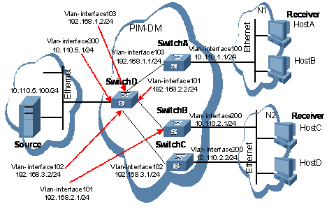
Figure 6-10 Network diagram for PIM-DM configuration
III. Configuration procedure
1) Configuring the interface IP addresses and unicast routing protocol for each switch
Configure the IP address and subnet mask for each interface as per Figure 6-10. Detailed configuration steps are omitted here.
Configure the OSPF protocol for interoperation among the switches in the PIM-DM domain. Ensure the network-layer interoperation among Switch A, Switch B, Switch C and Switch D in the PIM-DM domain and enable dynamic update of routing information among the switches through a unicast routing protocol. Detailed configuration steps are omitted here.
2) Enabling IP multicast routing, and enabling PIM-DM on each interface
# Enable IP multicast routing on Switch A, enable PIM-DM on each interface, and enable IGMPv3 on Vlan-interface100, which connects Switch A to the stub network.
<SwitchA> system-view
[SwitchA] multicast routing-enable
[SwitchA] interface vlan-interface 100
[SwitchA-Vlan-interface100] igmp enable
[SwitchA-Vlan-interface100] igmp version 3
[SwitchA-Vlan-interface100] pim dm
[SwitchA-Vlan-interface100] quit
[SwitchA] interface vlan-interface 103
[SwitchA-Vlan-interface103] pim dm
[SwitchA-Vlan-interface103] quit
The configuration on Switch B and Switch C is similar to the configuration on Switch A.
# Enable IP multicast routing on Switch D, and enable PIM-DM on each interface.
<SwitchD> system-view
[SwitchD] multicast routing-enable
[SwitchD] interface vlan-interface 300
[SwitchD-Vlan-interface300] pim dm
[SwitchD-Vlan-interface300] quit
[SwitchD] interface vlan-interface 103
[SwitchD-Vlan-interface103] pim dm
[SwitchD-Vlan-interface103] quit
[SwitchD] interface vlan-interface 101
[SwitchD-Vlan-interface101] pim dm
[SwitchD-Vlan-interface101] quit
[SwitchD] interface vlan-interface 102
[SwitchD-Vlan-interface102] pim dm
[SwitchD-Vlan-interface102] quit
3) Verifying the configuration
Carry out the display pim interface command to view the PIM configuration and running status on each interface. For example:
# View the PIM configuration information on Switch D.
[SwitchD] display pim interface
Vpn-instance: public net
Interface NbrCnt HelloInt DR-Pri DR-Address
Vlan300 0 30 1 10.110.5.1
Vlan103 1 30 1 192.168.1.2
Vlan101 1 30 1 192.168.2.2
Vlan102 1 30 1 192.168.3.2
Carry out the display pim neighbor command to view the PIM neighboring relationships among the switches. For example:
# View the PIM neighboring relationships on Switch D.
[SwitchD] display pim neighbor
Vpn-instance: public net
Total Number of Neighbors = 3
Neighbor Interface Uptime Expires Dr-Priority
192.168.1.1 Vlan103 00:02:22 00:01:27 1
192.168.2.1 Vlan101 00:00:22 00:01:29 3
192.168.3.1 Vlan102 00:00:23 00:01:31 5
Assume that Host A needs to receive the information addressed to a multicast group G (225.1.1.1/24). After multicast source S (10.110.5.100/24) sends multicast packets to the multicast group G, an SPT is established through traffic flooding. Switches on the SPT path (Switch A and Switch D) have their (S, G) entries. Host A registers with Switch A, and a (*, G) entry is generated on Switch A. You can use the display pim routing-table command to view the PIM routing table information on each switch. For example:
# View the PIM routing table information on Switch A.
[SwitchA] display pim routing-table
Vpn-instance: public net
Total 1 (*, G) entry; 1 (S, G) entry
(*, 225.1.1.1)
Protocol: pim-dm, Flag: WC
UpTime: 00:04:25
Upstream interface: NULL
Upstream neighbor: NULL
RPF prime neighbor: NULL
Downstream interface(s) information:
Total number of downstreams: 1
1: Vlan-interface100
Protocol: igmp, UpTime: 00:04:25, Expires: never
(10.110.5.100, 225.1.1.1)
Protocol: pim-dm, Flag: ACT
UpTime: 00:06:14
Upstream interface: Vlan-interface103,
Upstream neighbor: 192.168.1.2
RPF prime neighbor: 192.168.1.2
Downstream interface(s) information:
Total number of downstreams: 1
1: Vlan-interface100
Protocol: pim-dm, UpTime: 00:04:25, Expires: never
The information on Switch B and Switch C is similar to that on Switch A.
# View the PIM routing table information on Switch D.
[SwitchD] display pim routing-table
Vpn-instance: public net
Total 0 (*, G) entry; 1 (S, G) entry
(10.110.5.100, 225.1.1.1)
Protocol: pim-dm, Flag: LOC ACT
UpTime: 00:03:27
Upstream interface: Vlan-interface300
Upstream neighbor: NULL,
RPF prime neighbor: NULL
Downstream interface(s) information:
Total number of downstreams: 3
1: Vlan-interface103
Protocol: pim-dm, UpTime: 00:03:27, Expires: never
2: Vlan-interface101
Protocol: pim-dm, UpTime: 00:03:27, Expires: never
3: Vlan-interface102
Protocol: pim-dm, UpTime: 00:03:27, Expires: never
6.7.2 PIM-SM Configuration Example
I. Network requirements
l Receivers receive VOD information through multicast. The receiver groups of different organizations form stub networks, and one or more receiver hosts exist in each stub network. The entire PIM domain operates in the single-BSR sparse mode.
l Host A and Host C are multicast receivers in two stub networks.
l Switch D connects to the network that comprises the multicast source (Source) through Vlan-interface300.
l Switch A connects to stub network N1 through Vlan-interface100, and to Switch D and Switch E through Vlan-interface101 and Vlan-interface102 respectively.
l Switch B and Switch C connect to stub network N2 through their respective Vlan-interface200, and to Switch E through Vlan-interface103 and Vlan-interface104 respectively.
l Switch E connects to Switch A, Switch B, Switch C and Switch D, and its Vlan-interface102 interface acts a C-BSR and a C-RP.
II. Network diagram
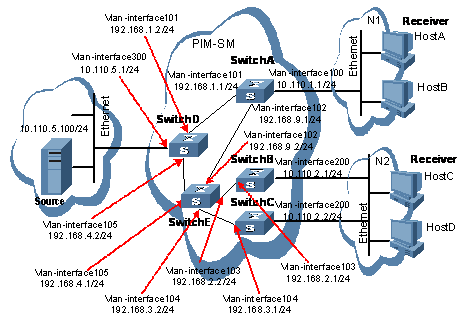
Figure 6-11 Network diagram for single-BSR PIM-SM domain configuration
III. Configuration procedure
1) Configuring the interface IP addresses and unicast routing protocol for each switch
Configure the IP address and subnet mask for each interface as per Figure 6-11. Detailed configuration steps are omitted here.
Configure the OSPF protocol for interoperation among the switches in the PIM-SM domain. Ensure the network-layer interoperation among Switch A, Switch B, Switch C, Switch D and Switch E in the PIM-DM domain and enable dynamic update of routing information among the switches through a unicast routing protocol. Detailed configuration steps are omitted here.
2) Enabling IP multicast routing, and enabling PIM-SM on each interface
# Enable IP multicast routing on Switch A, enable PIM-SM on each interface, and enable IGMPv3 on Vlan-interface100, which connects Switch A to the stub network.
<SwitchA> system-view
[SwitchA] multicast routing-enable
[SwitchA] interface vlan-interface 100
[SwitchA-Vlan-interface100] igmp enable
[SwitchA-Vlan-interface100] igmp version 3
[SwitchA-Vlan-interface100] pim sm
[SwitchA-Vlan-interface100] quit
[SwitchA] interface vlan-interface 101
[SwitchA-Vlan-interface101] pim sm
[SwitchA-Vlan-interface101] quit
[SwitchA] interface vlan-interface 102
[SwitchA-Vlan-interface102] pim sm
[SwitchA-Vlan-interface102] quit
The configuration on Switch B and Switch C is similar to that on Switch A. The configuration on Switch D and Switch E is also similar to that on Switch A except that it is not necessary to enable IGMP on the corresponding interfaces on these two switches.
3) Configuring a C-BSR and a C-RP
# Configure the service scope of RP advertisements and the positions of the C-BSR and C-RP on Switch E.
<SwitchE> system-view
[SwitchE] acl number 2005
[SwitchE-acl-basic-2005] rule permit source 225.1.1.0 0.0.0.255
[SwitchE-acl-basic-2005] quit
[SwitchE] pim
[SwitchE-pim] c-bsr vlan-interface 102
[SwitchE-pim] c-rp vlan-interface 102 group-policy 2005
4) Verifying the configuration
Carry out the display pim interface command to view the PIM configuration and running status on each interface. For example:
# View the PIM configuration information on Switch A.
[SwitchA] display pim interface
Vpn-instance: public net
Interface NbrCnt HelloInt DR-Pri DR-Address
Vlan100 0 30 1 10.110.1.1 (local)
Vlan101 1 30 1 192.168.1.2
Vlan102 1 30 1 192.168.9.2
To view the BSR election information and the locally configured C-RP information in effect on a switch, use the display pim bsr-info command. For example:
# View the BSR information and the locally configured C-RP information in effect on Switch A.
[SwitchA] display pim bsr-info
Vpn-instance: public net
Current BSR Address: 192.168.9.2
Priority: 0
Hash mask length: 30
State: Accept Preferred
Scope: Not scoped
Uptime: 01:40:40
Next BSR message scheduled at: 00:01:42
# View the BSR information and the locally configured C-RP information in effect on Switch E.
[SwitchE] display pim bsr-info
Vpn-instance: public net
Current BSR Address: 192.168.9.2
Priority: 0
Hash mask length: 30
State: Elected
Scope: Not scoped
Uptime: 00:00:18
Next BSR message scheduled at: 00:01:52
To view the RP information discovered on a switch, use the display pim rp-info command. For example:
# View the RP information on Switch A.
[SwitchA] display pim rp-info
Vpn-instance: public net
PIM-SM BSR RP information:
Group/MaskLen: 225.1.1.0/24
RP: 192.168.9.2
Priority: 0
HoldTime: 150
Uptime: 00:51:45
Next BSR message scheduled at: 00:02:22
Assume that Host A needs to receive information addressed to the multicast group G (225.1.1.1/24). An RPT will be built between Switch A and Switch E. When the multicast source S (10.110.5.100/24) registers with RP, an SPT will be built between Switch D and Switch E. Upon receiving multicast data, Switch A immediately switches from the RPT to the SPT. Switches on the RPT path, (Switch A and Switch E for example) contain (*, G) entries, while routers on the SPT path (Switch A and Switch D for example) contain an (S, G) entry. You can use the display pim routing-table command to view the PIM routing table information on the switches. For example:
# View the PIM routing table information on Switch A.
[SwitchA] display pim routing-table
Vpn-instance: public net
Total 1 (*, G) entry; 1 (S, G) entry
(*, 225.1.1.1), RP: 192.168.9.2
Protocol: pim-sm, Flag: WC
UpTime: 00:13:46
Upstream interface: Vlan-interface102,
Upstream neighbor: 192.168.9.2
RPF prime neighbor: 192.168.9.2
Downstream interface(s) information:
Total number of downstreams: 1
1: Vlan-interface100
Protocol: pim-sm, UpTime: 00:13:46, Expires: -
(10.110.5.100, 225.1.1.1), RP: 192.168.9.2
Protocol: pim-sm, Flag: SPT LOC
UpTime: 00:00:42
Upstream interface: Vlan-interface101,
Upstream neighbor: 192.168.9.2
RPF prime neighbor: 192.168.9.2
Downstream interface(s) information:
Total number of downstreams: 1
1: Vlan-interface100
Protocol: pim-sm, UpTime: 00:00:42, Expires:-
The information on Switch B and Switch C is similar to that on Switch A.
# View the PIM routing table information on Switch D.
[SwitchD] display pim routing-table
Vpn-instance: public net
Total 0 (*, G) entry; 1 (S, G) entry
(10.110.5.100, 225.1.1.1), RP: 192.168.9.2
Protocol: pim-sm, Flag: SPT LOC
UpTime: 00:00:42
Upstream interface: Vlan-interface300
Upstream neighbor: 10.110.5.100
RPF prime neighbor: 10.110.5.100
Downstream interface(s) information:
Total number of downstreams: 1
1: Vlan-interface105
Protocol: pim-sm, UpTime: 00:00:42, Expires:-
# View the PIM routing table information on Switch E.
[SwitchE] display pim routing-table
Vpn-instance: public net
Total 1 (*, G) entry; 0 (S, G) entry
(*, 225.1.1.1), RP: 192.168.9.2 (local)
Protocol: pim-sm, Flag: WC
UpTime: 00:13:16
Upstream interface: Register
Upstream neighbor: 192.168.4.2
RPF prime neighbor: 192.168.4.2
Downstream interface(s) information:
Total number of downstreams: 1
1: Vlan-interface102
Protocol: pim-sm, UpTime: 00:13:16, Expires: 00:03:22
6.7.3 PIM-SSM Configuration Example
I. Network requirements
l Receivers receive VOD information through multicast. The receiver groups of different organizations form stub networks, and one or more receiver hosts exist in each stub network. The entire PIM domain operates in the SSM mode.
l Host A and Host C are multicast receivers in two stub networks.
l Switch D connects to the network that comprises the multicast source (Source) through Vlan-interface300.
l Switch A connects to stub network N1 through Vlan-interface100, and to Switch D and Switch E through Vlan-interface101 and Vlan-interface102 respectively.
l Switch B and Switch C connect to stub network N2 through their respective Vlan-interface200, and to Switch E through Vlan-interface103 and Vlan-interface104 respectively.
l Switch E connects to Switch A, Switch B, Switch C and Switch D.
l The range of SSM multicast group addresses is 232.1.1.0/24.
l IGMPv3 runs between Switch A and stub network N1, and between (Router B and Router C) and stub networks N2.
II. Network diagram
Figure 6-12 Network diagram for PIM-SSM configuration
III. Configuration procedure
1) Configuring the interface IP addresses and unicast routing protocol for each switch
Configure the IP address and subnet mask for each interface as per Figure 6-12. Detailed configuration steps are omitted here.
Configure the OSPF protocol for interoperation among the switches in the PIM-SM domain. Ensure the network-layer interoperation among Switch A, Switch B, Switch C, Switch D and Switch E in the PIM-DM domain and enable dynamic update of routing information among the switches through a unicast routing protocol. Detailed configuration steps are omitted here.
2) Enabling IP multicast routing, and enabling PIM-SM on each interface
# Enable IP multicast routing on Switch A, enable PIM-SM on each interface, and enable IGMPv3 on Vlan-interface100, which connects Switch A to the stub network.
<SwitchA> system-view
[SwitchA] multicast routing-enable
[SwitchA] interface vlan-interface 100
[SwitchA-Vlan-interface100] igmp enable
[SwitchA-Vlan-interface100] igmp version 3
[SwitchA-Vlan-interface100] pim sm
[SwitchA-Vlan-interface100] quit
[SwitchA] interface vlan-interface 101
[SwitchA-Vlan-interface101] pim sm
[SwitchA-Vlan-interface101] quit
[SwitchA] interface vlan-interface 102
[SwitchA-Vlan-interface102] pim sm
[SwitchA-Vlan-interface102] quit
The configuration on Switch B and Switch C is similar to that on Switch A. The configuration on Switch D and Switch E is also similar to that on Switch A except that it is not necessary to enable IGMP on the corresponding interfaces on these two switches.
3) Configuring the range of PIM-SSM multicast group addresses
# Configure the range of PIM-SSM multicast group addresses to be 232.1.1.0/24 one Switch A.
[SwitchA] acl number 2000
[SwitchA-acl-basic-2000] rule permit ip source 232.1.1.0 0.0.0.255
[SwitchA-acl-basic-2000] quit
[SwitchA] pim
[SwitchA-pim] ssm-policy 2000
The configuration on Switch B, Switch C, Switch D and Switch E is similar to the configuration on Switch A.
4) Verifying the configuration
Carry out the display pim interface command to view the PIM configuration and running status on each interface. For example:
# View the PIM configuration information on Switch A.
[SwitchA] display pim interface
Vpn-instance: public net
Interface NbrCnt HelloInt DR-Pri DR-Address
Vlan100 0 30 1 10.110.1.1 (local)
Vlan101 1 30 1 192.168.1.2
Vlan102 1 30 1 192.168.9.2
Assume that Host A needs to receive the information a specific multicast source S (10.110.5.100/24) sends to multicast group G (232.1.1.1/24). Switch A builds an SPT towards the multicast source. Switches on the SPT path (Switch A and Switch D for example) generates (S, G) entries, while Switch E, which is not on the SPT path does not have multicast routing entries. You can use the display pim routing-table command to view the PIM routing table information on each switch. For example:
# View the PIM multicast routing table information on Switch A.
[SwitchA] display pim routing-table
Vpn-instance: public net
Total 0 (*, G) entry; 1 (S, G) entry
(10.110.5.100, 232.1.1.1)
Protocol: pim-ssm, Flag:
UpTime: 00:13:25
Upstream interface: Vlan-interface101
Upstream neighbor: 192.168.1.2
RPF prime neighbor: 192.168.1.2
Downstream interface(s) information:
Total number of downstreams: 1
1: Vlan-interface100
Protocol: pim-ssm, UpTime: 00:13:25, Expires: -
The information on Switch B and Switch C is similar to that on Switch A.
# View the PIM multicast routing table information on Switch D.
[SwitchD] display pim routing-table
Vpn-instance: public net
Total 0 (*, G) entry; 1 (S, G) entry
(10.110.5.100, 232.1.1.1)
Protocol: pim-ssm, Flag:
UpTime: 00:12:05
Upstream interface: Vlan-interface300
Upstream neighbor: 10.110.5.100
RPF prime neighbor: 10.110.5.100
Downstream interface(s) information:
Total number of downstreams: 1
1: Vlan-interface105
Protocol: pim, UpTime: 00:12:05, Expires: 00:03:25
6.8 Troubleshooting PIM Configuration
6.8.1 Failure of Building a Multicast Distribution Tree Correctly
I. Symptom
None of the routers in the network (including routers directly connected with multicast sources and receivers) has multicast forwarding entries. That is, a multicast distribution tree cannot be built correctly and clients cannot receive multicast data.
II. Analysis
l When PIM-DM runs on the entire network, multicast data is flooded from the first hop router connected with the multicast source to the last hop router connected with the clients along the SPT. When the multicast data is flooded to a router, no matter which router is, it creates (S, G) entries only if it has a route to the multicast source. If the router does not have a route to the multicast source, or if PIM-DM is not enabled on the router’s RPF interface to the multicast source, the router cannot create (S, G) entries.
l When PIM-SM runs on the entire network, and when a router is to join the SPT, the router creates (S, G) entries only if it has a route to the multicast source. If the router does not have a router to the multicast source, or if PIM-DM is not enabled on the router’s RPF interface to the multicast source, the router cannot create (S, G) entries.
l When a multicast router receives a multicast packet, it searches the existing unicast routing table for the optimal route to the RPF check object. The outgoing interface of this route will act as the RPF interface and the next hop will be taken as the RPF neighbor. The RPF interface completely relies on the existing unicast route, and is independent of PIM. The RPF interface must be PIM-enabled, and the RPF neighbor must also be a PIM neighbor. If PIM is not enabled on the router where the RPF interface or the RPF neighbor resides, the establishment of a multicast distribution tree will surely fail.
l Because a hello message does not carry the PIM mode information, a router running PIM is unable to know what PIM mode its PIM neighbor is running. If different PIM modes are enabled on the RPF interface and on the corresponding interface of the RPF neighbor router, the establishment of a multicast distribution tree will surely fail.
l The same PIM mode must run on the entire network. Otherwise, the establishment of a multicast distribution tree will surely fail.
III. Solution
1) Check unicast routes. Use the display ip routing-table command to check whether a unicast route exist from the receiver host to the multicast source.
2) Check that PIM is enabled on the interfaces, especially on the RPF interface. Use the display pim interface command to view the PIM information on each interface. If PIM is not enabled on the interface, use the pim dm or pim sm command to enable PIM-DM or PIM-SM.
3) Check that the RPF neighbor is a PIM neighbor. Use the display pim neighbor command to view the PIM neighbor information.
4) Check that PIM is enabled on the interfaces directly connecting to the multicast source and to the receivers.
5) Check that the same PIM mode is enabled on related interfaces. Use the display pim interface verbose command to check whether the same PIM mode is enabled on the RPF interface and the corresponding interface of the RPF neighbor router.
6) Check that the same PIM mode is enabled on all the routers in the entire network. Make sure that the same PIM mode is enabled on all the routers: PIM-SM on all routers, or PIM-DM on all routers. In the case of PIM-SM, also check that the BSR and RP configurations are correct.
6.8.2 Multicast Data Abnormally Terminated on an Intermediate Router
I. Symptom
An intermediate router can receive multicast data successfully, but the data cannot reach the last hop router. An interface on the intermediate router receives data but no corresponding (S, G) entry is created in the PIM routing table.
II. Analysis
l If a multicast forwarding boundary has been configured through the multicast boundary command, any multicast packet will be kept from crossing the boundary, and therefore no routing entry can be created in the PIM routing table.
l In addition, the source-policy command is used to filter received multicast packets. If the multicast data fails to pass the ACL rule defined in this command, PIM cannot create the route entry, either.
III. Solution
1) Check the multicast forwarding boundary configuration. Use the display current-configuration command to check the multicast forwarding boundary settings. Use the multicast boundary command to change the multicast forwarding boundary settings.
2) Check the multicast filter configuration. Use the display current-configuration command to check the multicast filter configuration. Change the ACL rule defined in the source-policy command so that the source/group address of the multicast data can pass ACL filtering.
6.8.3 RPs Unable to Join SPT in PIM-SM
I. Symptom
An RPT cannot be established correctly, or the RPs cannot join the SPT to the multicast source.
II. Analysis
l As the core of a PIM-SM domain, the RPs serve specific multicast groups. Multiple RPs can coexist in a network. Make sure that the RP information on all routers is exactly the same, and a specific group is mapped to the same RP. Otherwise, multicast will fail.
l If the static RP mechanism is used, the same static RP command must be executed on all the routers in the entire network. Otherwise, multicast will fail.
III. Solution
1) Check that a route is available to the RP. Carry out the display ip routing-table command to check whether a route is available on each router to the RP.
2) Check the dynamic RP information. Use the display pim rp-info command to check whether the RP information is consistent on all routers.
3) Check the configuration of static RPs. Use the display pim rp-info command to check whether the same static RP address has been configured on all the routers in the entire network.
6.8.4 No Unicast Route Between BSR and C-RPs in PIM-SM
I. Symptom
C-RPs cannot unicast advertise messages to the BSR. The BSR does not advertise bootstrap messages containing C-RP information and has no unicast route to any C-RP. An RPT cannot be established correctly, or the DR cannot perform source register with the RP.
II. Analysis
l The C-RPs periodically sends C-RP-Adv messages to the BSR by unicast. If a C-RP has no unicast route to the BSR, the BSR cannot receive C-RP-Adv messages from that C-RP and the bootstrap message of the BSR will not contain the information of that C-RP.
l In addition, if the BSR does not have a unicast router to a C-RP, it will discard the C-RP-Adv messages from that C-RP, and therefore the bootstrap messages of the BSR will not contain the information of that C-RP.
l The RP is the core of a PIM-SM domain. Make sure that the RP information on all routers is exactly the same, a specific group G is mapped to the same RP, and unicast routes are available to the RP.
III. Solution
1) Check whether routes to C-RPs, the RP and the BSR are available. Carry out the display ip routing-table command to check whether routes are available on each router to the RP and the BSR, and whether a route is available between the RP and the BSR. Make sure that each C-RP has a unicast route to the BSR, the BSR has a unicast route to each C-RP, and all the routers in the entire network have a unicast route to the RP.
2) Check the RP and BSR information. PIM-SM needs the support of the RP and BSR. Use the display pim bsr-info command to check whether the BSR information is available on each router, and then use the display pim rp-info command to check whether the RP information is correct.
3) View PIM neighboring relationships. Use the display pim neighbor command to check whether the normal PIM neighboring relationships have been established among the routers.
Chapter 7 MSDP Configuration
7.1 MSDP Overview
7.1.1 Introduction to MSDP
Multicast source discovery protocol (MSDP) is an inter-domain multicast solution based on the interconnection of protocol independent multicast sparse mode (PIM-SM) domains. It is used to discover the multicast source information in other PIM-SM domains.
Within a PIM-SM domain, the multicast source registers only with the local rendezvous point (RP). Therefore, an RP knows all the multicast sources only in its own domain. If there is a mechanism that allows the RPs of different PIM-SM domains to share their multicast source information, the information of multicast sources active in other domains can be transmitted to receivers in the local domain, and thus multicast packets can be transmitted among different domains. MSDP makes this possible. By setting up MSDP peer relationships among RPs of different domains, multicast data can be forwarded among these domains and the information of the multicast sources can be shared.
![]() Caution:
Caution:
l MSDP is applicable only if the intra-domain multicast protocol is PIM-SM;
l MSDP is meaningful only for the any-source multicast (ASM) model.
l Unless otherwise stated, MSDP peers mentioned in this manual refer to RPs that are MSDP peers to one another.
7.1.2 How MSDP Works
I. MSDP peers
When an active multicast source exists in a PIM-SM domain, the RP in this domain can learn this through the process of source registration. If a PIM-SM domain managed by another Internet service provider (ISP) wants to obtain information from this multicast source, an MSDP peer relationship must be set up between the routers in the these two PIM-SM domains.
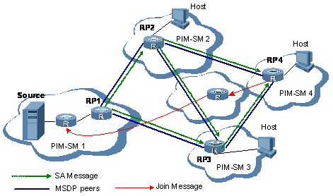
Figure 7-1 shows the MSDP peering relationships set up between RPs.
l An active multicast source (Source in the figure) exists in the domain PIM-SM1. RP1 in this network knows the location of Source through the multicast source registration process, and periodically sends source active (SA) messages to MSDP peers in other PIM-SM domains. This SA message contains the source address (S), the multicast group address (G), and the address of the RP which has generated this SA message. Moreover, it also contains the first multicast packet received by the RP in the domain PIM-SM1.
l The SA message is forwarded and finally reaches all MSDP peers. In this way, the information of the multicast source in PIM-SM is propagated to all other PIM-SM domains. The MSDP peers performs reverse path forwarding (RPF) check on the SA messages, an MSDP peer forwards only SA messages received from the correct paths. This mechanism avoids path loops of SA messages. In addition, the configuration of a mesh group can prevent SA messages from flooding among MSDP peers.
l As shown in Figure 7-1, upon receiving this SA message, RP4 in the domain PIM-SM4 checks whether receivers exist in the corresponding multicast group. If so, it sends an (S, G) Join message, which is forwarded hop by hop to Source, and thus a shortest path tree (SPT) is built based on Source. Whereas, a rendezvous point tree (RPT) is built between RP4 and receivers in PIM-SM4.
& Note:
l An MSDP mesh group is a group of MSDP peers that have fully meshed MSDP connectivity among one another.
l MSDP peers are connected to each other over TCP (using port 639). Such a TCP connection can be established between RPs of different PIM-SM domains, or between RPs of the same PIM-SM domains, or between an RP and command router, or between common routers.
l When using MSDP for inter-domain multicasting, once an RP receives information form the multicast source, it no longer relies on RPs in other PIM-SM domains. The receivers can override the RPs in different domains and directly join the multicast source based SPT.
II. Implementation of Anycast RP with MSDP
Anycast RP is an application in which MSDP peering relationships are formed between two or more RPs with the same IP address in a PIM-SM domain to achieve load balancing and redundancy backup among the RPs.
In a PIM-SM domain, you can configure different routers as candidate RPs (C-RPs) by configuring the same IP address (known as anycast RP address, which is often a private address) on an interface (often loopback interface) of these routers, and set up MSDP peering relationships among these routers, as shown in Figure 7-2.
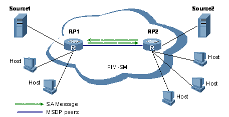
Figure 7-2 Typical network diagram of anycast RP
A multicast source typically selects to register to the nearest RP to build an SPT; a receiver also sends a Join message to the nearest RP to build its RPT. Therefore, the RP with which a multicast source registers is not necessarily the RP the receivers have joined. These peer RPs obtain the multicast source information of one another by sending SA messages. Finally, all the RP have learned the information of all multicast sources in the PIM-SM domain. Thus, the receivers on all the RPs can receive multicast data from all the multicast sources in the entire PIM-SM domain.
As RPs communicate with one another through MSDP and multicast sources or receivers initiate registration to or join the nearest RP respectively, load balancing can be achieved among the RPs.
When an RP fails, the multicast source that has registered to it or the receivers that have joined it will register to or join another nearest RP. Thus, redundancy backup among the RPs is achieved.
![]() Caution:
Caution:
l Be sure to configure a 32-bit subnet mast (255.255.255.255) for an anycast RP address; namely configure it into a host address.
l During configuration, make sure that an MSDP peer address is different from an anycast RP address.
7.1.3 Operation Mechanism of MSDP
I. Multicast source identification and multicast date reception
As shown in Figure 7-3, the network comprises four PIM-SM domains, which are PIM-SM1, PIM-SM2, PIM-SM3, and PIM-SM4. All RPs in these domains are MSDP peers to one another, and PIM-SM1 and PIM-SM4 have multicast members.
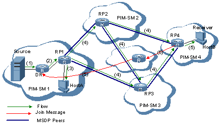
Figure 7-3 Multicast source identification and multicast date reception
When the multicast source (Source) in PIM-SM1 sends multicast data to the multicast group, the receivers in PIM-SM1 and PIM-SM4 get the information about Source through MSDP and successfully receive the multicast data from Source. The specific process is as follows:
1) Source in PIM-SM1 starts to send multicast data.
2) The designated router (DR) connected to Source encapsulates the multicast data within a register message and sends it to RP1.
3) RP1 decapsulates the register message and forwards the multicast data down to all the members along the RPT in the domain and sends a join message to the multicast source. The members in the domain can choose whether to switch to the SPT.
4) At the same time, RP1 generates an SA message, and sends the SA message its MSDP peers (RP2 and RP3), Finally, the message is forwarded to RP4. This SA message contains the multicast source address, the multicast group address, the address of RP1, which has generated this SA message, and the first multicast packet received by RP1. In this process, to avoid forwarding loops, the MSDP peers perform RPF check on the received SA message. The SA message will be discarded if it fails the RPF check.
5) If any member (receiver) exists in the domain where an MSDP peer of RP1 resides, for example, if a receiver exists in PIM-SM4, RP4 decapsulates the multicast data in the SA message and forwards the multicast data down to the receivers along the RPT. At the same time, RP4 sends a Join message to the multicast source. Now, the router connecting the group members in PIM-SM4 can choose whether to switch to the SPT.
II. Message forwarding between MSDP peers
Assume that there are three autonomous systems (ASs), AS1, AS2 and AS3. Each AS has one or several PIM-SM domains, each PIM-SM domain contains a RP, and the RPs are MSDP peers to one another. RP3, RP3 and RP4 form a mesh group, as shown in Figure 7-4.
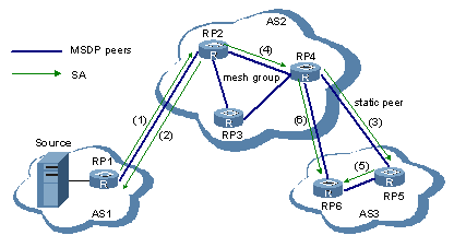
Figure 7-4 Message forwarding between MSDP peers
The following describes how the MSDP peers handle SA messages forwarded among one another:
l When an SA message is from an RP of the domain where the multicast source is located, this message is accepted and forwarded to other peers. For example, when RP1 sends an SA messages to RP2, RP2 accepts the message and forwards it to RP3 and RP4.
l If a router has only one MSDP peer, the router will accept all the SA messages from that peer. For example, when RP2 sends an SA message to RP1, RP1 accepts the message.
l When an RP receives an SA message from a static RPF peer, the RP accepts the SA message and forwards it to other peers. For example, when RP4 sends an SA messages to RP5, RP5 accepts the message and forwards it to RP6.
l When an RP receives an SA message from the MSDP mesh group it belongs to, the RP accepts the SA message and forwards it to peers out side of the message group. For example, when RP2 sends an SA messages to RP4, RP4 accepts the message and forwards it to RP5 and RP6.
l When an RP receives an SA message from an MSDP peer in the same AS to which the RP belongs, if this MSDP peer is the next hop on the optimal path to the PIM-SM domain where the multicast source is located, the RP accepts the message and forwards it to other peers. For example, when RP5 sends an SA message to RP6, RP6 accepts the message.
l When an RP receives an SA message from an MSDP peer in a different AS, if this AS is the next AS on the optimal path to the PIM-SM domain where the multicast source is located, the RP accepts the message and forwards it to other peers. For example, when RP4 sends an SA message to RP6, RP6 accepts the message.
l When an RP receives an SA message other than as described above, the RP does not accept nor forward the message.
7.1.4 MSDP-Related Specifications
For MSDP-related specifications, refer to:
l RFC 3618: Multicast Source Discovery Protocol (MSDP)
l RFC 3446: Anycast Rendezvous Point (RP) mechanism using protocol independent multicast (PIM) and multicast source discovery protocol (MSDP)
7.2 Configuring MSDP
Complete these tasks to configure MSDP:
|
Task |
Remarks |
|
|
Required |
||
|
Required |
||
|
Optional |
||
|
Optional |
||
|
Optional |
||
|
Optional |
||
|
Optional |
||
|
Optional |
||
|
Optional |
||
|
Optional |
||
7.3 Configuring Basic Functions of MSDP
& Note:
All the configuration tasks shall be implemented on RPs in PIM-SM domains, and each of these RPs acts as an MSDP peer.
7.3.1 Configuration Prerequisites
Before configuring the basic functions of MSDP, complete the following tasks:
l Configure any unicast routing protocol so that all devices in the domain are interoperable at the network layer.
l Configuring PIM-SM
Before configuring the basic functions of MSDP, prepare the following data:
l IP addresses of MSDP peers
l Address prefix list for an RP address filtering policy
7.3.2 Enabling MSDP
Before configuring any MSDP functionality, follow these steps to enable MSDP:
|
To do... |
Use the command... |
Remarks |
|
Enter system view |
system-view |
— |
|
Enable IP multicast routing |
multicast routing-enable |
Required Disabled by default |
|
Enable MSDP and enter MSDP view |
msdp |
Required Disabled by default |
7.3.3 Creating an MSDP Peer Connection
MSDP peering is the relationship between two PIM-SM RPs. An MSDP peering relationship is identified by an address pair, namely the address of the local MSDP peer and that of the remote MSDP peer.
Follow these steps to create an MSDP peer connection on both peers:
|
To do... |
Use the command... |
Remarks |
|
Enter system view |
system-view |
— |
|
Enter MSDP view |
msdp |
— |
|
Create an MSDP peer connection |
peer peer-address connect-interface interface-type interface-number |
Required No MSDP peer connection created by default |
& Note:
If an interface of the router is shared by an MSDP peer and a BGP peer at the same time, we recommend that you configuration the same IP address for the MSDP peer and BGP peer.
7.3.4 Configuring a Static RPF Peer
A BGP route should be available between two MSDP peer routers so that SA messages can be exchanged directly over this route between the PIM-SM domains. If such a route does not exist, static RPF peers must be configured.
For domains that have only one MSDP peer (known as stub domains), no BGP route is required between MSDP peers, and SA messages are delivered by means of static RPF peers and the existing routes among the ASs.
Configuring static RPF peers can avoid RPF check on SA messages.
Follow these steps to configure a static RPF peer:
|
To do... |
Use the command... |
Remarks |
|
Enter system view |
system-view |
— |
|
Enter MSDP view |
msdp |
— |
|
Configure a static RPF peer |
static-rpf-peer peer-address [ rp-policy ip-prefix-name ] |
Required No static RPF peer configured by default |
& Note:
If only one MSDP peer is configured on a router, this MSDP will be registered as a static RPF peer.
7.4 Configuring an MSDP Peer Connection
7.4.1 Configuration Prerequisites
Before configuring MSDP peer connection, complete the following tasks:
l Configure any unicast routing protocol so that all devices in the domain are interoperable at the network layer.
l Configuring basic functions of MSDP
Before configuring an MSDP peer connection, prepare the following data:
l Description information of MSDP peers
l Name of an MSDP peer mesh group
l MSDP peer connection retry interval
7.4.2 Configuring MSDP Peer Description
With the MSDP peer description information, the administrator can easily distinguish different MSDP peers and thus better manage MSDP peers.
Follow these steps to configure description for an MSDP peer:
|
To do... |
Use the command... |
Remarks |
|
Enter system view |
system-view |
— |
|
Enter MSDP view |
msdp |
— |
|
Configure description for an MSDP peer |
peer peer-address description text |
Required No description for MSDP peers by default |
7.4.3 Configuring an MSDP Mesh Group
An AS may contain multiple MSDP peers. You can use the MSDP mesh group mechanism to avoid SA message flooding among these MSDP peers and optimize the multicast traffic.
On one hand, an MSDP peer in a mesh group receives SA messages from outside the mesh group and forwards them to the other members in the mesh group; on the other hand, a mesh group member accepts SA messages from inside the group without an RPF check, and does not forwarded the message on. This mechanism not only avoids SA flooding but also simplifies the RPF check mechanism, because BGP is not needed to run between these MSDP peers.
Follow these steps to configure an MSDP mesh group:
|
To do... |
Use the command... |
Remarks |
|
Enter system view |
system-view |
— |
|
Enter MSDP view |
msdp |
— |
|
Configure an MSDP peer as a mesh group member |
peer peer-address mesh-group name |
Required An MSDP peer does not belong to any mesh group by default |
& Note:
l Before grouping multiple routers into an MSDP mesh group, make sure that these routers are interconnected with one another.
l By assigning the same mesh group name for multiple routers, you can set up mesh group of these MSDP peers.
l If you configure more than one mesh group name on an MSDP peer, only the last configuration is effective.
7.4.4 Configuring MSDP Peer Connection Control
You can temporarily deactivate the MSDP peering relationships between certain peers, and reactivate them later as needed. When the connection between two MSDP peers is deactivated, SA messages will no longer be delivered between them, and the TCP connection is closed without any connection setup retry, but the configuration information will remain unchanged.
When a previously deactivated MSDP peer connection is reestablished, or when a previously failed MSDP peer resumes operation, the MSDP peer keeps making TCP connection setup attempts until the connection is successfully set up.
Follow these steps to configure MSDP peer connection control:
|
To do... |
Use the command... |
Remarks |
|
Enter system view |
system-view |
— |
|
Enter MSDP view |
msdp |
—- |
|
Deactivate an MSDP peer |
shutdown peer-address |
Optional Active by default |
|
Configure the interval between MSDP peer connection retries |
timer retry interval |
Optional 30 seconds by default |
7.5 Configuring SA Messages
7.5.1 Configuration Prerequisites
Before configuring SA message delivery, complete the following tasks:
l Configure any unicast routing protocol so that all devices in the domain are interoperable at the network layer.
l Configuring basic functions of MSDP
Before configuring SA message delivery, prepare the following data:
l ACL as a filtering rule for SA request messages
l ACL as an SA message creation rule
l ACL as a filtering rule for receiving or forwarding SA messages
l Minimum TTL value of multicast packets encapsulated in SA messages
l Maximum SA message cache size
7.5.2 Configuring SA Message Content
An SA message contains the multicast source address, the multicast group address, and the address of the RP which has generated this SA message. Moreover, it can also contain the first multicast packet received by the RP of the domain where the multicast source is located. In the case of some burst multicast data, such as multicast data whose transmission interval exceeds the SA message hold time, the first multicast packet must be encapsulated within an SA message; otherwise, the receivers will never receive the information from the multicast source.
The MSDP peers deliver SA messages to one another. Upon receiving an SA message, a router performs RPF check on the message. If the router finds that the remote RP address is the same as the local RP address, it will discard the SA message. In the Anycast RP application, however, you need to configure RPs with the same IP address on two or more routers in the same PIM-SM domain, and configure these routers as MSDP peers to one another. Therefore, a logic RP address (namely the RP address on the logic interface) that is different from the actual RP address must be designated for SA messages so that the messages can pass the RPF check.
Follow these steps to configure the SA message content:
|
To do... |
Use the command... |
Remarks |
|
Enter system view |
system-view |
— |
|
Enter MSDP view |
msdp |
— |
|
Enable encapsulation of the first multicast packet |
encap-data-enable |
Optional Disabled by default |
|
Configure the interface address as the RP address of SA messages |
originating-rp interface-type interface-number |
Optional By default, the RP address of an SA message is the PIM RP address |
& Note:
In the anycast RP application, an MSDP peer address must be different from the anycast RP address, and the C-BSR and C-RP must be configured on different devices or interfaces. Generally, the C-BSR and C-RP of a PIM-SM domain are configured on the same router and share the same interface address. In the anycast RP application, however, multiple RPs use the same address, and each DR registers the multicast source directly connected with it to the nearest RP, while there is only one active BSR in a PIM-SM domain. Therefore, if you configure the same C-BSR address and RP address on a router, when another C-RP check a received BSR message, it will reject the BSR message because the BSR address in the message is the local address. As a result, the other routers configured with C-RP will not consider themselves as RPs, and thus the anycast RP function will fail.
7.5.3 Configuring SA Request Messages
Follow these steps to configure SA message transmission and filtering:
|
To do... |
Use the command... |
Remarks |
|
Enter system view |
system-view |
— |
|
Enter MSDP view |
msdp |
— |
|
Enable the device to send SA request messages |
peer peer-address request-sa-enable |
Optional Disabled by default |
|
Configure a filtering rule for SA request messages |
peer peer-address sa-request-policy [ acl acl-number ] |
Optional SA request messages are not filtered by default |
7.5.4 Configuring an SA Message Filtering Rule
By configuring an SA message creation rule, you can enable the router to filter the (S, G) entries to be advertised when creating an SA message, so that the propagation of messages of multicast sources is controlled.
In addition to controlling SA message creation, you can also configure filtering rules for forwarding and receiving SA messages, so as to control the propagation of multicast source information in the SA messages.
l By configuring a filtering rule for receiving or forwarding SA messages, you can enable the router to filter the (S, G) forwarding entries to be advertised when receiving or forwarding an SA message, so that the propagation of multicast source information is controlled at SA message reception or forwarding.
l An SA message with encapsulated multicast data can be forwarded to a designated MSDP peer only if the TTL value in its IP header exceeds the threshold. Therefore, you can control the forwarding of such an SA message by configuring the TTL threshold of the encapsulated data packet.
Follow these steps to configure a filtering rule for receiving or forwarding SA messages:
|
To do... |
Use the command... |
Remarks |
|
Enter system view |
system-view |
— |
|
Enter MSDP view |
msdp |
— |
|
Configuring an SA message creation rule |
import-source [ acl acl-number ] |
Required No restrictions on (S, G) entries by default |
|
Configure a filtering rule for receiving or forwarding SA messages |
peer peer-address sa-policy { import | export } [ acl acl-number ] |
Required No filtering rule by default |
|
Configure the minimum TTL value of multicast packets to be encapsulated in SA messages |
peer peer-address minimum-ttl ttl-value |
Optional 0 by default |
7.5.5 Configuring SA Message Cache
To reduce the time spent in obtaining the multicast source information, you can have MA messaged cached on the router. However, the more SA messages are cached, the larger memory space of the router is used.
With the SA cache mechanism enabled, when receiving a new Join message, the router will not send an SA request message to its MSDP peer; instead, it acts as follows:
l If there is no SA message in the cache, the router will wait for the SA message sent by its MSDP peer in the next cycle;
l If there is an SA message in the cache, the router will obtain the information of all active sources directly from the SA message and join the corresponding SPT.
To protect the router against denial of service (DoS) attacks, you can configure the maximum number of SA messages the route can cache.
Follow these steps to configure the SA message cache:
|
To do... |
Use the command... |
Remarks |
|
Enter system view |
system-view |
— |
|
Enter MSDP view |
msdp |
— |
|
Enable the SA message cache mechanism |
cache-sa-enable |
Optional Enabled by default |
|
Configure the maximum number of SA messages the router can cache |
peer peer-address sa-cache-maximum sa-limit |
Optional 8192 by default |
7.6 Displaying and Maintaining MSDP
|
To do... |
Use the command... |
Remarks |
|
View the brief information of MSDP peers |
display msdp brief [ state { connect | down | listen | shutdown | up } ] |
Available in any view |
|
View the detailed information about the status of MSDP peers |
display msdp peer-status [ peer-address ] |
|
|
View the (S, G) entry information in the MSDP cache |
display msdp sa-cache [ group-address | source-address | as-number ] * |
|
|
View the number of SA messages in the MSDP cache |
display msdp sa-count [ as-number ] |
|
|
Reset the TCP connection with an MSDP peer |
reset msdp peer [ peer-address ] |
Available in user view |
|
Clear (S, G) entries in the MSDP cache |
reset msdp sa-cache [ group-address ] |
|
|
Clear all statistics information of an MSDP peer |
reset msdp statistics [ peer-address ] |
7.7 MSDP Configuration Examples
7.7.1 Example of Configuration Leveraging BGP Routes
I. Network requirements
l Two ISPs maintains their ASs, AS 100 and AS 200 respectively. OSPF is running within each AS, and BGP is running between the two ASs.
l PIM-SM1 belongs to AS 100, while PIM-SM2 and PIM-SM3 belong to AS 200.
l Both PIM-SM domains are single-BSR-managed domains, each having 0 or 1 multicast source and multiple receivers. OSPF runs within each domain to provide unicast routes.
l The respective loopback interfaces of Switch C, Switch D and Switch F are configured as the C-BSR and C-RP of the respective PIM-SM domains.
l An MSDP peering relationship is set up between Switch C and Switch F based on EBGP, and an MSDP peering relationship is set up between Switch F and Switch D based on IBGP.
II. Network diagram
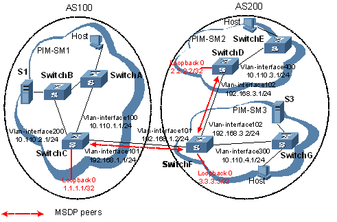
Figure 7-5 Network diagram for configuration leveraging BGP routes
III. Configuration procedure
1) Configuring the interface IP addresses and unicast routing protocol for each switch
Configure the IP address and subnet mask for each interface as per Figure 7-5. Detailed configuration steps are omitted here.
Configure OSPF for interconnection between switches in each PIM-SM domain. Ensure the network-layer interoperation among Switch A, Switch B and Switch C in PIM-SM1, the network-layer interoperation between Switch D and Switch E in PIM-SM2, and the network-layer interoperation between Switch F and Switch G in PIM-SM3, and ensure the dynamic update of routing information between the switches in each PIM-SM domain through a unicast routing protocol. Detailed configuration steps are omitted here.
2) Enabling IP multicast routing, and enable PIM-SM on each interface
# Enable IP multicast routing on Switch C, and enable PIM-SM on each interface.
<SwitchC> system-view
[SwitchC] multicast routing-enable
[SwitchC] interface vlan-interface 100
[SwitchC-Vlan-interface100] pim sm
[SwitchC-Vlan-interface100] quit
[SwitchC] interface vlan-interface 200
[SwitchC-Vlan-interface200] pim sm
[SwitchC-Vlan-interface200] quit
[SwitchC] interface vlan-interface 101
[SwitchC-Vlan-interface101] pim sm
The configuration on Switch A, Switch B, Switch D, Switch E, Switch F and Switch G is similar to the configuration on Switch C.
# Configure BSR boundary on Switch C.
[SwitchC-Vlan-interface101] pim bsr-boundary
[SwitchC-Vlan-interface101] quit
The configuration on Switch D and Switch F is similar to the configuration on Switch C.
3) Configure the position of interface Loopback 0, C-BSR, and C-RP.
# Configure the position of Loopback 0, C-BSR, and C-RP on Switch C.
[SwitchC] interface loopback 0
[SwitchC-LoopBack0] ip address 1.1.1.1 255.255.255.255
[SwitchC-LoopBack0] pim sm
[SwitchC-LoopBack0] quit
[SwitchC] pim
[SwitchC-pim] c-bsr loopback 0
[SwitchC-pim] c-rp loopback 0
[SwitchC-pim] quit
The configuration on Switch D and Switch F is similar to the configuration on Switch C.
4) Configuring inter-AS BGP for mutual route redistribution between BGP and OSPF
# Configure EBGP on Switch C, and inject OSPF routes.
[SwitchC] bgp 100
[SwitchC-bgp] router-id 1.1.1.1
[SwitchC-bgp] peer 192.168.1.2 as-number 200
[SwitchC-bgp] import-route ospf 1
[SwitchC-bgp] quit
# Configure IBGP and EBGP on Switch F, and inject OSPF routes.
[SwitchF] bgp 200
[SwitchF-bgp] router-id 3.3.3.3
[SwitchF-bgp] peer 192.168.1.1 as-number 100
[SwitchF-bgp] peer 192.168.3.1 as-number 200
[SwitchF-bgp] import-route ospf 1
[SwitchF-bgp] quit
# Configure EBGP on Switch D, and inject OSPF routes.
[SwitchD] bgp 200
[SwitchD-bgp] router-id 2.2.2.2
[SwitchD-bgp] peer 192.168.3.2 as-number 200
[SwitchD-bgp] import-route ospf 1
[SwitchD-bgp] quit
# Inject BGP routes into OSPF on Switch C.
[SwitchC] ospf 1
[SwitchC-ospf-1] import-route bgp
[SwitchC-ospf-1] quit
The configuration on Switch D and Switch F is similar to the configuration on Switch C.
Carry out the display bgp peer command to view the BGP peering relationships between the switch. For example:
# View the information about BGP peering relationships on Switch C.
[SwitchC] display bgp peer
BGP local router ID : 1.1.1.1
Local AS number : 100
Total number of peers : 1 Peers in established state : 1
Peer V AS MsgRcvd MsgSent OutQ PrefRcv Up/Down State
# View the information about BGP peering relationships on Switch D.
[SwitchD] display bgp peer
BGP local router ID : 2.2.2.2
Local AS number : 200
Total number of peers : 1 Peers in established state : 1
Peer V AS MsgRcvd MsgSent OutQ PrefRcv Up/Down State
192.168.3.2 4 200 21 20 0 6 00:12:05 Established
# View the information about BGP peering relationships on Switch F.
[SwitchF] display bgp peer
BGP local router ID : 3.3.3.3
Local AS number : 200
Total number of peers : 2 Peers in established state : 2
Peer V AS MsgRcvd MsgSent OutQ PrefRcv Up/Down State
192.168.1.1 4 100 18 16 0 1 00:12:04 Established
192.168.3.1 4 200 16 14 0 1 00:10:58 Established
To view the BGP routing table information on the switches, use the display bgp routing-table command. For example:
# View the BGP routing table information on Switch F.
[SwitchF] display bgp routing-table
Total Number of Routes: 13
BGP Local router ID is 3.3.3.3
Status codes: * - valid, > - best, d - damped,
h - history, i - internal, s - suppressed, S - Stale
Origin : i - IGP, e - EGP, ? - incomplete
Network NextHop MED LocPrf PrefVal Path/Ogn
*> 1.1.1.1/32 192.168.1.1 0 0 100?
*>i 2.2.2.2/32 192.168.3.1 0 100 0 ?
*> 3.3.3.3/32 0.0.0.0 0 0 ?
*> 192.168.1.0 0.0.0.0 0 0 ?
* 192.168.1.1 0 0 100?
*> 192.168.1.1/32 0.0.0.0 0 0 ?
*> 192.168.1.2/32 0.0.0.0 0 0 ?
* 192.168.1.1 0 0 100?
*> 192.168.3.0 0.0.0.0 0 0 ?
* i 192.168.3.1 0 100 0 ?
*> 192.168.3.1/32 0.0.0.0 0 0 ?
*> 192.168.3.2/32 0.0.0.0 0 0 ?
* i 192.168.3.1 0 100 0 ?
5) Configuring MSDP peers
# Configure an MSDP peer on Switch C.
[SwitchC] msdp
[SwitchC-msdp] peer 192.168.1.2 connect-interface vlan-interface 101
[SwitchC-msdp] quit
# Configure an MSDP peer on Switch D.
[SwitchD] msdp
[SwitchD-msdp] peer 192.168.3.2 connect-interface vlan-interface 102
[SwitchD-msdp] quit
# Configure MSDP peers on Switch F.
[SwitchF] msdp
[SwitchF-msdp] peer 192.168.1.1 connect-interface vlan-interface 101
[SwitchF-msdp] peer 192.168.3.1 connect-interface vlan-interface 102
[SwitchF-msdp] quit
When the multicast source S1 sends multicast information, receivers in PIM-SM2 and PIM-SM3 can receive the multicast data. You can use the display msdp brief command to view the brief information of MSDP peering relationships between the switches. For example:
# View the brief information about MSDP peering relationships on Switch C.
[SwitchC] display msdp brief
MSDP Peer Brief Information
Configured Up Listen Connect Shutdown Down
1 1 0 0 0 0
Peer's Address State Up/Down time AS SA Count Reset Count
192.168.1.2 Up 00:12:27 200 13 0
# View the brief information about MSDP peering relationships on Switch D.
[SwitchD] display msdp brief
MSDP Peer Brief Information
Configured Up Listen Connect Shutdown Down
1 1 0 0 0 0
Peer's Address State Up/Down time AS SA Count Reset Count
192.168.3.2 Up 00:15:32 200 8 0
# View the brief information about MSDP peering relationships on Switch F.
[SwitchF] display msdp brief
MSDP Peer Brief Information
Configured Up Listen Connect Shutdown Down
2 2 0 0 0 0
Peer's Address State Up/Down time AS SA Count Reset Count
192.168.3.1 UP 01:07:08 200 8 0
192.168.1.1 UP 00:06:39 100 13 0
# View the detailed BGP peer information on Switch C.
[SwitchC] display msdp peer-status
MSDP Peer 192.168.1.2, AS 200
Description:
Information about connection status:
State: Up
Up/down time: 00:15:47
Resets: 0
Connection interface: Vlan-interface101 (192.168.1.1)
Number of sent/received messages: 16/16
Number of discarded output messages: 0
Elapsed time since last connection or counters clear: 00:17:51
Information about (Source, Group)-based SA filtering policy:
Import policy: none
Export policy: none
Information about SA-Requests:
Policy to accept SA-Request messages: none
Sending SA-Requests status: disable
Minimum TTL to forward SA with encapsulated data: 0
SAs learned from this peer: 0, SA-cache maximum for the peer: none
Input queue size: 0, Output queue size: 0
Counters for MSDP message:
Count of RPF check failure: 0
Incoming/outgoing SA messages: 0/0
Incoming/outgoing SA requests: 0/0
Incoming/outgoing SA responses: 0/0
Incoming/outgoing data packets: 0/0
7.7.2 Example of Anycast RP Application Configuration
I. Network requirements
l The PIM-SM domain is this example is a single-BSR-managed domain with multiple multicast sources and receivers. OSPF runs within the domain to provide unicast routes.
l The anycast RP application is configured in the PIM-SM domain. When a new member joins the multicast group, the switch directly connected to receivers can initiate a Join message to the topologically nearest RP.
l An MSDP peering relationship is set up between Switch C and Switch D.
l On Switch C and Switch D, the interface Loopback 1 is configured as a C-BSR, and Loopback 10 is configured as a C-RP.
l The router ID of Switch C is 1.1.1.1, while the router ID of Switch D is 2.2.2.2.
II. Network diagram
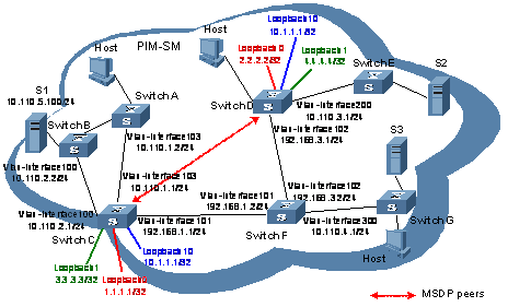
Figure 7-6 Network diagram for anycast RP configuration
III. Configuration procedure
1) Configuring the interface IP addresses and unicast routing protocol for each switch
Configure the IP address and subnet mask for each interface as per Figure 7-6. Detailed configuration steps are omitted here.
Configure OSPF for interconnection between the switches. Detailed configuration steps are omitted here.
2) Enabling IP multicast routing, and enable PIM-SM on each interface
# Enable IP multicast routing on Switch C, and enable PIM-SM on each interface.
<SwitchC> system-view
[SwitchC] multicast routing-enable
[SwitchC] interface vlan-interface 103
[SwitchC-Vlan-interface103] pim sm
[SwitchC-Vlan-interface103] quit
[SwitchC] interface vlan-interface 100
[SwitchC-Vlan-interface100] pim sm
[SwitchC-Vlan-interface100] quit
[SwitchC] interface Vlan-interface 101
[SwitchC-Vlan-interface101] pim sm
[SwitchC-Vlan-interface101] quit
The configuration on Switch A, Switch B, Switch D, Switch E, Switch F and Switch G is similar to the configuration on Switch C.
3) Configure the position of interface Loopback 1, Loopback 10, C-BSR, and C-RP.
# Configure different Loopback 1 addresses and identical Loopback 10 address on Switch C and Switch D, configure C-BSR on each Loopback 1 and configure C-RP on each Loopback 10.
[SwitchC] interface loopback 1
[SwitchC-LoopBack1] ip address 3.3.3.3 255.255.255.255
[SwitchC-LoopBack1] pim sm
[SwitchC-LoopBack1] quit
[SwitchC] interface loopback 10
[SwitchC-LoopBack10] ip address 10.1.1.1 255.255.255.255
[SwitchC-LoopBack10] pim sm
[SwitchC-LoopBack10] quit
[SwitchC] pim
[SwitchC-pim] c-bsr loopback 1
[SwitchC-pim] c-rp loopback 10
[SwitchC-pim] quit
The configuration on Switch D is similar to the configuration on Switch C.
To view the PIM routing information on the switches, use the display pim routing-table command. When the multicast source S1 (10.110.5.100/24) in the PIM-SM domain sends multicast data to the multicast group G (225.1.1.1/24), the receivers attached to Switch D can receive the multicast data. By comparing the PIM routing information displayed on Switch C with that displayed on Switch D, you can see that Switch C acts now as the RP.
# View the PIM routing information on Switch C.
[SwitchC] display pim routing-table
Vpn-instance: public net
Total 0 (*, G) entry; 1 (S, G) entry
(10.110.5.100, 225.1.1.1), RP: 10.1.1.1 (local)
Protocol: pim-sm, Flag: SPT LOC ACT
UpTime: 00:10:20
Upstream interface: Vlan-interface100
RPF neighbor: 10.110.1.2
Downstream interface(s) information:
Total number of downstreams: 1
1: Vlan-interface101
Protocol: pim-sm, UpTime: 00:10:20, Expires: 00:03:10
# View the PIM routing information on Switch D.
[SwitchD] display pim routing-table
Vpn-instance: public net
Total 0 (*, G) entry; 1 (S, G) entry
(10.110.5.100, 225.1.1.1), RP: 10.1.1.1
Protocol: pim-sm, Flag: SPT ACT
UpTime: 00:03:32
Upstream interface: Vlan-interface102
RPF neighbor: 192.168.3.2
Downstream interface(s) information:
Total number of downstreams: 1
1: Vlan-interface200
Protocol: pim-sm, UpTime: 00:03:32, Expires: -
4) Configuring Loopback 0 and MSDP peers
# Configure an MSDP peer on Loopback 0 of Switch C.
[SwitchC] interface loopback 0
[SwitchC-LoopBack0] ip address 1.1.1.1 255.255.255.255
[SwitchC-LoopBack0] pim sm
[SwitchC-LoopBack0] quit
[SwitchC] msdp
[SwitchC-msdp] originating-rp loopback 0
[SwitchC-msdp] peer 2.2.2.2 connect-interface loopback 0
[SwitchC-msdp] quit
# Configure an MSDP peer on Loopback 0 of Switch D.
[SwitchD] interface loopback 0
[SwitchD-LoopBack0] ip address 2.2.2.2 255.255.255.255
[SwitchD-LoopBack0] pim sm
[SwitchD-LoopBack0] quit
[SwitchD] msdp
[SwitchD-msdp] originating-rp loopback 0
[SwitchD-msdp] peer 1.1.1.1 connect-interface loopback 0
[SwitchD-msdp] quit
You can use the display msdp brief command to view the brief information of MSDP peering relationships between the switches.
# View the brief MSDP peer information on Switch C.
[SwitchC] display msdp brief
MSDP Peer Brief Information
Configured Up Listen Connect Shutdown Down
1 1 0 0 0 0
Peer's Address State Up/Down time AS SA Count Reset Count
2.2.2.2 Up 00:10:17 ? 0 0
# View the brief MSDP peer information on Router D.
[SwitchD] display msdp brief
MSDP Peer Brief Information
Configured Up Listen Connect Shutdown Down
1 1 0 0 0 0
Peer's Address State Up/Down time AS SA Count Reset Count
1.1.1.1 Up 00:10:18 ? 0 0
7.7.3 Static RPF Peer Configuration Example
I. Network requirements
l Two ISPs maintains their ASs, AS 100 and AS 200 respectively. OSPF is running within each AS, and BGP is running between the two ASs.
l PIM-SM1 belongs to AS 100, while PIM-SM2 and PIM-SM3 belong to AS 200.
l Both PIM-SM domains are single-BSR-managed domains, each having 0 or 1 multicast source and multiple receivers. OSPF runs within each domain to provide unicast routes.
l PIM-SM2 and PIM-SM3 are both PIM stub domains, and BGP or MBGP is not required between these two domains and PIM-SM1. Instead, static RPF peers are configured to avoid RPF check on SA messages.
l The respective loopback interfaces of Switch C, Switch D and Switch F are configured as the C-BSR and C-RP of the respective PIM-SM domains.
l The static RPF peers of Switch C are Switch D and Switch F, while Switch C is the only RPF peer of Switch D and Switch F. Any switch can receive the SA messages sent by its static RPF peer(s) and permitted by the corresponding filtering policy.
II. Network diagram
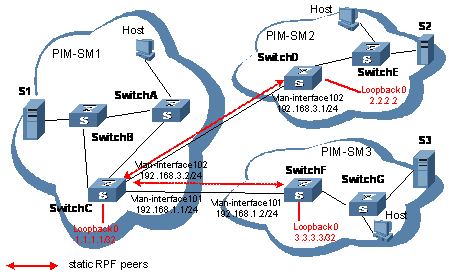
Figure 7-7 Network diagram for static RPF peer configuration
III. Configuration procedure
Configuring the interface IP addresses and unicast routing protocol for each switch
Configure the IP address and subnet mask for each interface as per Figure 7-7. Detailed configuration steps are omitted here.
Configure OSPF for interconnection between the switches. Ensure the network-layer interoperation among Switch A, Switch B and Switch C in PIM-SM1, the network-layer interoperation between Switch D and Switch E in PIM-SM2, and the network-layer interoperation between Switch F and Switch G in PIM-SM3, and ensure the dynamic update of routing information between the switches in each PIM-SM domain through a unicast routing protocol.
Configuring EBGP among Switch C, Switch D, Switch C and Switch F, and configure mutual route redistribution between BGP and OSPF. Detailed configuration steps are omitted here.
1) Enabling IP multicast routing, and enable PIM-SM on each interface
# Enable IP multicast routing on Switch C, and enable PIM-SM on each interface.
<SwitchC> system-view
[SwitchC] multicast routing-enable
[SwitchC] interface vlan-interface 101
[SwitchC-Vlan-interface101] pim sm
[SwitchC-Vlan-interface101] quit
[SwitchC] interface vlan-interface 102
[SwitchC-Vlan-interface102] pim sm
The configuration on Switch A, Switch B, Switch D, Switch E, Switch F and Switch G is similar to the configuration on Switch C.
# Configure BSR boundary on Switch C.
[SwitchC-Vlan-interface102] pim bsr-boundary
[SwitchC-Vlan-interface102] quit
[SwitchC] interface vlan-interface 101
[SwitchC-Vlan-interface101] pim bsr-boundary
[SwitchC-Vlan-interface101] quit
The configuration on Switch D and Switch F is similar to the configuration on Switch C.
2) Configure the position of interface Loopback 0, C-BSR, and C-RP.
# Configure the position of Loopback 0, C-BSR, and C-RP on Switch C.
[SwitchC] router-id 1.1.1.1
[SwitchC] interface loopback 0
[SwitchC-LoopBack0] ip address 1.1.1.1 255.255.255.255
[SwitchC-LoopBack0] pim sm
[SwitchC-LoopBack0] quit
[SwitchC] pim
[SwitchC-pim] c-bsr loopback 0
[SwitchC-pim] c-rp loopback 0
[SwitchC-pim] quit
The configuration on Switch D and Switch F is similar to the configuration on Switch C.
3) Configuring a static RPF peer
# Configure Switch D and Switch F as static RPF peers of Switch C.
[SwitchC] ip ip-prefix list-df permit 192.168.0.0 16 greater-equal 16 less-equal 32
[SwitchC] msdp
[SwitchC-msdp] peer 192.168.3.1 connect-interface vlan-interface 102
[SwitchC-msdp] peer 192.168.1.2 connect-interface vlan-interface 101
[SwitchC-msdp] static-rpf-peer 192.168.3.1 rp-policy list-df
[SwitchC-msdp] static-rpf-peer 192.168.1.2 rp-policy list-df
[SwitchC-msdp] quit
# Configure Switch C as static RPF peer of Switch D.
[SwitchD] ip ip-prefix list-c permit 192.168.0.0 16 greater-equal 16 less-equal 32
[SwitchD] msdp
[SwitchD-msdp] peer 192.168.3.2 connect-interface vlan-interface 102
[SwitchD-msdp] static-rpf-peer 192.168.3.2 rp-policy list-c
[SwitchD-msdp] quit
# Configure Switch C as static RPF peer of Switch F.
[SwitchF] ip ip-prefix list-c permit 192.168.0.0 16 greater-equal 16 less-equal 32
[SwitchF] msdp
[SwitchF-msdp] peer 192.168.3.2 connect-interface vlan-interface 102
[SwitchF-msdp] static-rpf-peer 192.168.3.2 rp-policy list-c
[SwitchF-msdp] quit
4) Verify the configuration
Carry out the display bgp peer command to view the BGP peering relationships between the switches. If the command gives no output information, a BGP peering relationship has not been established between the switches.
When the multicast source S1 sends multicast information, receivers in PIM-SM2 and PIM-SM3 can receive the multicast data. You can use the display msdp brief command to view the brief information of MSDP peering relationships between the switches. For example:
# View the brief MSDP peer information on Switch C.
[SwitchC] display msdp brief
MSDP Peer Brief Information
Configured Up Listen Connect Shutdown Down
2 2 0 0 0 0
Peer's Address State Up/Down time AS SA Count Reset Count
192.168.3.1 UP 01:07:08 ? 8 0
192.168.1.2 UP 00:16:39 ? 13 0
# View the brief MSDP peer information on Router D.
[SwitchD] display msdp brief
MSDP Peer Brief Information
Configured Up Listen Connect Shutdown Down
1 1 0 0 0 0
Peer's Address State Up/Down time AS SA Count Reset Count
192.168.3.2 UP 01:07:09 ? 8 0
# View the brief MSDP peer information on Switch F.
[SwitchF] display msdp brief
MSDP Peer Brief Information
Configured Up Listen Connect Shutdown Down
1 1 0 0 0 0
Peer's Address State Up/Down time AS SA Count Reset Count
192.168.3.2 UP 00:16:40 ? 13 0
7.8 Troubleshooting MSDP
7.8.1 MSDP Peers Stay in Down State
I. Symptom
The configured MSDP peers stay in the down state.
II. Analysis
l A TCP connection–based MSDP peering relationship is established between the local interface address and the MSDP peer after the configuration.
l The TCP connection setup will fail if there is a consistency between the local interface address and the MSDP peer address configured on the router.
l If no route is available between the MSDP peers, the TCP connection setup will also fail.
III. Solution
1) Check that a route is available between the routers. Carry out the display ip routing-table command to check whether the unicast route between the routers is correct.
2) Check that a unicast route is available between the two routers that will become MSDP peers to each other.
3) Verify the interface address consistency between the MSDP peers. Use the display current-configuration command to verify that the local interface address and the MSDP peer address of the remote router are the same.
7.8.2 No SA Entries in the Router’s SA Cache
I. Symptom
MSDP fails to send (S, G) entries through SA messages.
II. Analysis
l The import-source command is used control sending (S, G) entries through SA messages to MSDP peers. If this command is executed without the acl-number argument, all the (S, G) entries will be filtered off, namely no (S, G) entries of the local domain will be advertised.
l If the import-source command is not executed, the system will advertise all the (S, G) entries of the local domain. If MSDP fails to send (S, G) entries through SA messages, check whether the import-source command has been correct configured.
III. Solution
1) Check that a route is available between the routers. Carry out the display ip routing-table command to check whether the unicast route between the routers is correct.
2) Check that a unicast route is available between the two routers that will become MSDP peers to each other.
3) Check configuration of the import-source command and its acl-number argument and make sure that ACL rule can filter appropriate (S, G) entries.
7.8.3 Inter-RP Communication Faults in Anycast RP Application
I. Symptom
RPs fail to exchange their locally registered (S, G) entries with one another in the Anycast RP application.
II. Analysis
l In the Anycast RP application, RPs in the same PIM-SM domain are configured to be MSDP peers to achieve load balancing among the RPs.
l An MSDP peer address must be different from the anycast RP address, and the C-BSR and C-RP must be configured on different devices or interfaces.
l If the originating-rp command is executed, MSDP will replace the RP address in the SA messages with the address of the interface specified in the command.
l When an MSDP peer receives an SA message, it performs RPF check on the message. If the MSDP peer finds that the remote RP address is the same as the local RP address, it will discard the SA message.
III. Solution
1) Check that a route is available between the routers. Carry out the display ip routing-table command to check whether the unicast route between the routers is correct.
2) Check that a unicast route is available between the two routers that will become MSDP peer to each other.
3) Check the configuration of the originating-rp command. In the Anycast RP application environment, be sure to use the originating-rp command to configure the RP address in the SA messages, which must be the local interface address.
4) Verify that the C-BSR address is different from the anycast RP address.
Chapter 8 Multicast Policy Configuration
8.1 Multicast Policy Overview
To ensure the correct transmission of multicast packets in the network, every multicast packet is subject to a reverse path forwarding (RPF) check on the incoming interface:
l If the packet passes the RPF check, the router creates the corresponding multicast forwarding entry and forwards the packet;
l If the packet fails the RPF check, it is discarded.
Multicast policies are policies used for filtering the RPF routing information.
8.1.1 Introduction to Multicast Policy
I. Multicast routing and forwarding
In multicast implementations, multicast routing and forwarding include three aspects:
l Each multicast routing protocol has its own multicast routing table, such as PIM routing table.
l The information of different multicast routing protocols forms a general multicast routing table.
l The multicast forwarding table is directly used to control the forwarding of multicast packets.
The multicast forwarding table consists of a group of (S, G) entries, each indicating a route from a multicast source to a multicast group. If a router supports multiple multicast protocols, its multicast routing table will include routes generated by multiple protocols. The router chooses the optimal route from the multicast routing table based on the configured multicast routing and forwarding policy and updates its multicast forwarding table accordingly.
The multicast forwarding table is the table that guides multicast forwarding. Upon receiving a multicast packet that a multicast source S sends to a multicast group G, the device first searches its multicast forwarding table:
l If the corresponding (S, G) entry exists, and the interface on which the packet has actually arrived is the incoming interface in the multicast forwarding table, the router forwards the packet to all the outgoing interfaces.
l If the corresponding (S, G) entry exists, but the interface on which the packet has actually arrived is not the incoming interface in the multicast forwarding table, the router performs an RPF check for the packet. If the packet passes the RPF check, the router modifies the incoming interface to the interface on which the packet has actually arrived and forwards the packet to all the outgoing interfaces; if the RFP check fails, the router discards the packet.
l If the corresponding (S, G) entry does not exist, the router performs an RPF check on the packet. If the packet passes the RPF check, the router creates the corresponding routing entry based on the related routing information and then installs the routing entry in the multicast forwarding table before forwarding the packet to all the outgoing interfaces; if the RFP check fails, the router discards the packet.
II. RPF mechanism
The process of an RPF check is as follows:
1) The router searches the unicast routing table for the RPF interface. The unicast routing table contains the shortest path to each destination address.
l When a packet arrives along the shortest path tree (SPT) from the multicast source to the receivers or along the source tree from the multicast source to the rendezvous point (RP), the router searches its unicast routing table using the IP address of the multicast source as the destination address. The outgoing interface of the corresponding entry is the RPF interface. The router assumes the path along which the packet has arrived on the RPF interface to be the shortest path from the multicast source to the local device.
l When a packet arrives along the rendezvous point tree (RPT) from the RP to the receivers, the router searches its unicast routing table using the IP address of the RP as the destination address. The outgoing interface of the corresponding entry is the RPF interface. The router assumes the path along which the packet has arrived on the RPF interface to be the shortest path from the RP to the local device.
& Note:
For details about the concepts of SPT, RPT and RP, refer to ”PIM Configuration”.
2) The router compares the RPF interface with the interface on which the packet has actually arrived to determine whether the path is correct and accordingly decides whether it should forward the multicast packet:
l If the RPF interface is the interface on which the packet has actually arrived, the packet passes the RPF check and is forwarded.
l If the RPF interface is not the interface on which the packet has actually arrived, the packet fails the RPF check and is discarded.
The unicast routing information used as the basis for the path judgment can originate from any unicast routing protocol or a multicast static route.
Figure 8-1 shows an RPF check for a multicast packet that arrives along the SPT from the multicast source to the receivers.
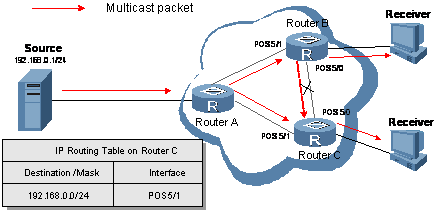
l A multicast packet from Source arrives on POS 5/0 of Router C, and the multicast forwarding table does not contain the corresponding forwarding entry. The router performs an RPF check, and finds in its unicast routing table that the outgoing interface on the shortest path to the subnet 192.168.0.0/24 is POS 5/1, so the router knows that the interface on which the packet has actually arrived is not the RPF interface. The packet fails the RPF check and is discarded.
l A multicast packet from Source arrives on POS 5/1 of Router C, and the multicast forwarding table does not contain the corresponding forwarding entry. The router performs an RPF check, and finds in its unicast routing table that the outgoing interface on the shortest path to the subnet 192.168.0.0/24 is the interface on which the packet has actually arrived. The packet passes the RPF check and is forwarded.
The RPF mechanism enables routers to correctly forward multicast packets based on the multicast route configuration. In addition, the RPF mechanism also helps avoid data loops caused by various reasons.
8.1.2 How a Multicast Policy Works
I. Multicast static route
If the topology structure of a multicast network is the same as that of a unicast network, receivers can receive multicast data via unicast routes. However, the topology structure a multicast network may differ from that of a unicast network, and some routers may support only unicast but not multicast. In this case, you can configure multicast static routes to provide multicast transmission paths that are different from those for unicast traffic. Note the following two points:
l A multicast static route is used only for RPF check, rather than for guiding multicast forwarding.
l A multicast static route is effective on the multicast router on which it is configured, and will not be broadcast throughout the network or injected to other routers.
During an RPF check after multicast static route configuration, the router searches the unicast routing table and the multicast static routing table simultaneously, chooses the optimal unicast RPF route and multicast static route respectively from the tables, and uses one of them as the RPF route after comparison.
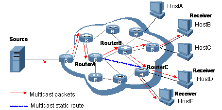
Figure 8-2 Multicast static route
As shown in Figure 8-2, when no multicast static route is configured, the RPF route is a unicast route that carries the multicast packets from Router A to Router C via Router B. After a static router from Router A is configured on Router C, the RPF route is updated to the direct route from Router A to Router C.
8.2 Configuration Tasks
Complete these tasks to configure a multicast policy:
|
Task |
Remarks |
|
Required |
|
|
Required |
|
|
Configuring a Multicast Route Match Policy |
Optional |
|
Optional |
|
|
Optional |
|
|
Optional |
8.3 Configuring a Multicast Policy
8.3.1 Configuration Prerequisites
Before configuring a multicast forwarding policy, complete the following tasks:
l Configure any unicast routing protocol so that all devices in the domain are interoperable at the network layer.
l Configure PIM-DM (PIM-SM)
Before configuring a multicast forwarding policy, prepare the following data:
l The minimum TTL required for a multicast packet to be forwarded
l The maximum number of downstream nodes for a single route in the multicast forwarding table
l The maximum number of routing entries in the multicast forwarding table
8.3.2 Enabling IP Multicast Routing
Follow these steps to enable IP multicast routing:
|
To do… |
Use the Command… |
Remarks |
|
Enter system view |
system-view |
— |
|
Enable IP multicast routing |
multicast routing-enable |
Required Disabled by default |
8.3.3 Configuring a Multicast Static Route
You can configure multicast static routes to provide multicast transmission paths that are different from those for unicast traffic.
Follow these steps to configure a static route:
|
To do... |
Use the command... |
Remarks |
|
Enter system view |
system-view |
— |
|
Configure a multicast static route |
ip rpf-route-static source-address { mask | mask-length } [ protocol [ process-id ] ] [ route-policy policy-name ] { rpf-nbr-address | interface-type interface-number } [ preference preference ] [ order order-number ] |
Required No multicast static route by default |
![]() Caution:
Caution:
l A maximum of eight different multicast static routes are allowed for each subnet.
l Configuring a multicast static route can change a multicast RPF route.
8.3.4 Configuring a Multicast Route Match Policy
In RPF route selection, the device chooses an optimal route from the multicast static routing table and from the unicast routing table respectively, and then chooses the better route from these two routes. The route match policy falls in two cases:
l In the case of route selection based on the longest match principle,
1) The router choose the longest-match route from the two routes;
2) If these two routes have the same mask, the route with a higher priority will be chosen;
3) If these two routes have the same priority, the route selection will be based the sequence of multicast static route – unicast route.
l If route selection is not based on the longest match principle,
4) The route with a higher priority will be chosen;
5) If these two routes have the same priority, the route selection will be based the sequence of multicast static route – unicast route.
Follow these steps to configure multicast a route match policy:
|
To do... |
Use the command… |
Remarks |
|
Enter system view |
system-view |
— |
|
Configure the device to select a route based on the longest match |
multicast longest-match |
Required In order of routing table entries by default |
8.3.5 Configuring Multicast Load Splitting
With the load splitting feature enabled, multicast traffic will be evenly distributed among different routes.
Follow these steps to enable multicast load spitting policies:
|
To do... |
Use the command... |
Remarks |
|
Enter system view |
system-view |
— |
|
Enable multicast load splitting |
multicast load-splitting { source | source-group } |
Required Disabled by default |
8.3.6 Configuring Multicast Forwarding Range
Multicast packets do not travel infinitely in a network. The multicast data corresponding to each multicast group must be transmitted within a definite scope. Presently, you can define a multicast forwarding range by:
l Specifying boundary interfaces, which form a closed multicast forwarding area, or
l Setting the minimum time to live (TTL) required for a multicast packet to be forwarded.
You can configure the forwarding boundary of a specific multicast group on all interfaces that support multicast forwarding. A multicast forwarding boundary sets the boundary condition for the multicast groups in the specified range. If the destination address of a multicast packet matches the set boundary condition, the packet will not be forwarded. Once a multicast boundary is configured on an interface, this interface can no longer forward multicast packets (including multicast packets sent from the local device) or receive multicast packets.
Follow these methods to configure a multicast forwarding range:
|
To do... |
Use the command... |
Remarks |
|
Enter system view |
system-view |
— |
|
Enter interface view |
interface interface-type interface-number |
— |
|
Configure a multicast forwarding boundary |
multicast boundary group-address { mask | mask-length } |
Required No forwarding boundary by default |
8.3.7 Configuring Multicast Forwarding Table Size
Too many multicast routing entries can exhaust the router’s memory and thus result in lower router performance. Therefore, the number of multicast routing entries should be limited. You can set a limit on the number of entries in the multicast routing table based on the actual networking situation and the performance requirements. In any case, the number of route entries must not exceed the maximum number defined by the system.
If the configured maximum number of downstream nodes (namely, the maximum number of outgoing interfaces) for a routing entry in the multicast forwarding table is smaller than the current number, the downstream nodes in excess of the configured limit will not be deleted immediately; instead they must be deleted by the multicast routing protocol. In addition, newly added downstream nodes cannot be installed to the routing entry in the forwarding table.
If the configured maximum number of routing entries in the multicast forwarding table is smaller than the current number, the routes in excess of the configured limit will not be deleted immediately; instead they must be deleted by the multicast routing protocol. In addition, newly added route entries cannot be installed to the forwarding table.
Follow these steps to configure the multicast forwarding table size:
|
To do... |
Use the command... |
Remarks |
|
Enter system view |
system-view |
— |
|
Configure the maximum number of downstream nodes for a single route in the multicast forwarding table |
multicast forwarding-table downstream-limit limit |
Required 128 by default |
|
Configure the maximum number of routing entries in the multicast forwarding table |
multicast forwarding-table route-limit limit |
Required 1,000 by default |
8.4 Displaying and Debugging a Multicast Policy
|
To do... |
Use the command... |
Remarks |
|
View the multicast boundary information |
display multicast boundary [ group-address [ mask | mask-length ] ] [ interface interface-type interface-number ] |
Available in any view |
|
View the multicast forwarding table information |
display multicast forwarding-table [ source-address [ mask { mask | mask-length } ] | group-address [ mask { mask | mask-length } ] | incoming-interface { interface-type interface-number | register } | outgoing-interface { { exclude | include | match } { interface-type interface-number | register } } | statistics | [ port-info ] [ verbose ] |
|
|
View the multicast routing table information |
display multicast routing-table [ source-address [ mask { mask | mask-length } ] | group-address [ mask { mask | mask-length } ] | incoming-interface { interface-type interface-number | register } | outgoing-interface { { exclude | include | match } { interface-type interface-number | register } } ] * |
|
|
View the information of the multicast static routing table |
display multicast routing-table static [ config ] [ source-address { mask-length | mask } ] |
|
|
View the RPF route information of the specified multicast source |
display multicast rpf-info source-address [ group-address ] |
|
|
Clear forwarding entries from the multicast forwarding table |
reset multicast forwarding-table { { source-address [ mask { mask | mask-length } ] | group-address [ mask { mask | mask-length } ] | incoming-interface { interface-type interface-number | register } } * | all } |
Available in user view |
|
Clear routing entries from the multicast routing table |
reset multicast routing-table { { source-address [ mask { mask | mask-length } ] | group-address [ mask { mask | mask-length } ] | incoming-interface { interface-type interface-number | register } } * | all } |
![]() Caution:
Caution:
l The reset command clears the information in the multicast forwarding table or the multicast routing table, and thus may cause failure of multicast transmission.
l When a forwarding entry is deleted from the multicast forwarding table, the corresponding route entry will also be deleted from the multicast routing table.
l When a route entry is deleted from the multicast routing table, the corresponding forwarding entry will also be deleted from the multicast forwarding table.
8.5 Configuration Example
8.5.1 Multicast Static Route Configuration
I. Network requirements
l All switches in the network support multicast.
l OSPF runs among Switch A, Switch B and Switch C.
l Receiver can receive the multicast data from Source 1 through the path Switch A – Switch B – Switch C.
l Through configuration, Receiver can receive multicast data from Source 2 out of the OSPF domain through Switch C.
II. Network diagram
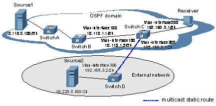
Figure 8-3 Network diagram for multicast static route configuration
III. Configuration procedure
1) Configuring the interface IP addresses and unicast routing protocol for each switch
Configure the IP address and subnet mask for each interface as per Figure 8-3. The detailed configuration steps are not discussed in this document.
Enable OSPF on Switch A, Switch B and Switch C. Ensure the network-layer interoperation among the routers. Ensure that the routers can dynamically update routing information by leveraging a unicast routing protocol. The specific configuration steps are omitted here.
2) Enabling IP multicast routing, and enable PIM on each interface
# Enable IP multicast routing on Switch C and enable PIM-DM on each interface.
<SwitchC> system-view
[SwitchC] multicast routing-enable
[SwitchC] interface vlan-interface 100
[SwitchC-Vlan-interface100] pim dm
[SwitchC-Vlan-interface100] quit
[SwitchC] interface vlan-interface 200
[SwitchC-Vlan-interface200] igmp enable
[SwitchC-Vlan-interface200] pim dm
[SwitchC-Vlan-interface200] quit
[SwitchC] interface vlan-interface 300
[SwitchC-Vlan-interface300] pim dm
[SwitchC-Vlan-interface300] quit
The configuration on Switch A, Switch B and Switch D is similar to the configuration on Switch C.
3) Configuring a multicast static route
# Configure a multicast static route on Switch C, and configure the address of the RPF check interface to be 192.168.3.2/24.
[SwitchC] ip rpf-route-static 10.220.5.100 255.255.255.0 192.168.3.2
4) Verifying the configuration
# Before the configuration of a multicast static route, Receiver can normally receive multicast data from Source1, and Switch C can receive multicast data from Switch B. The RPF information on Switch C is as follows:
[SwitchC] display multicast rpf-info 10.110.5.100
RPF information about source 10.110.5.100:
RPF interface: Vlan-interface100
Referenced route/mask: 10.110.5.0/24
Referenced route type: igp
Route selection rule: preference-preferred
Load splitting rule: disable
# View RPF neighbor information after configuring a multicast static route. You will find that the RPF upstream neighbor has changed. This is because the multicast static router is functioning. The RPF information on Switch C is as follows:
[SwitchC] display multicast rpf-info 10.220.5.100
RPF information about source 10.220.5.100:
RPF interface: Vlan-interface300
Referenced route/mask: 10.220.5.0/24
Referenced route type: unicast
Route selection rule: preference-preferred
Load splitting rule: disable
8.6 Troubleshooting Multicast Policies
8.6.1 Multicast Static Route Failure
I. Symptom
No dynamic routing protocol is enabled on the routers, and the physic status and link layer status of interfaces are both Up, but the multicast static route fails.
II. Analysis
l If the multicast static route is not configured or updated correctly to match the current network conditions, the route entry does not exist in the multicast static routing table and multicast routing table.
l If the optimal route if found, the multicast static route may also fail.
III. Solution
1) Use the display multicast routing-table static config command to view the detailed configuration information of multicast static routes to verify that the multicast static route has been correctly configured and the route entry exists.
2) In the configuration, you can use the display multicast routing-table static command to view the information of multicast static routes to verify that the multicast static route has been correctly configured and the route entry exists in the multicast routing table.
3) Check the next hop interface type of the multicast static route. If the interface is not a point-to-point interface, be sure to specify the next hop address to configure the outgoing interface when you configure the multicast static route.
4) Check that the multicast static route matches the specified routing protocol. If a protocol was specified when the multicast static route was configured, enter the display ip routing-table command to check if an identical route was added by the protocol.
5) Check that the multicast static route matches the specified routing policy. If a routing policy was specified when the multicast static route was configured, enter the display route-policy command to check the configured routing policy.
8.6.2 Multicast Data Fails to Reach Receivers
I. Symptom
The multicast data can reach some routers but fails to reach the last hop router.
II. Analysis
If a multicast forwarding boundary has been configured through the multicast boundary command, any multicast packet will be kept from crossing the boundary.
III. Solution
1) Use the display pim routing-table command to check whether the corresponding (S, G) entries exist on the router. If so, the router has received the multicast data; otherwise, the router has not received the data.
2) Use the display multicast boundary command to view the multicast boundary information on the interfaces. Use the multicast boundary command to change the multicast forwarding boundary setting.
3) In the case of PIM-SM, use the display current-configuration command to check the BSR and RP information.