- Table of Contents
-
- H3C S3600 Series Ethernet Switches Operation Manual-Release 1510(V1.04)
- 00-1Cover
- 00-2Product Overview
- 01-CLI Operation
- 02-Login Operation
- 03-Configuration File Management Operation
- 04-VLAN Operation
- 05-IP Address and Performance Configuration Operation
- 06-Management VLAN Operation
- 07-Voice VLAN Operation
- 08-GVRP Operation
- 09-Port Basic Configuration Operation
- 10-Link Aggregation Operation
- 11-Port Isolation Operation
- 12-Port Security-Port Binding Operation
- 13-DLDP Operation
- 14-MAC Address Table Operation
- 15-Auto Detect Operation
- 16-MSTP Operation
- 17-Routing Protocol Operation
- 18-Multicast Operation
- 19-802.1x Operation
- 20-AAA-RADIUS-HWTACACS-EAD Operation
- 21-VRRP Operation
- 22-Centralized MAC Address Authentication Operation
- 23-ARP Operation
- 24-DHCP Operation
- 25-ACL Operation
- 26-QoS-QoS Profile Operation
- 27-Web Cache Redirection Operation
- 28-Mirroring Operation
- 29-IRF Fabric Operation
- 30-Cluster Operation
- 31-PoE-PoE Profile Operation
- 32-UDP Helper Operation
- 33-SNMP-RMON Operation
- 34-NTP Operation
- 35-SSH Terminal Service Operation
- 36-File System Management Operation
- 37-FTP and TFTP Operation
- 38-Information Center Operation
- 39-System Maintenance and Debugging Operation
- 40-VLAN-VPN Operation
- 41-HWPing Operation
- 42-DNS Operation
- 43-Access Management Operation
- 44-Appendix
- Related Documents
-
| Title | Size | Download |
|---|---|---|
| 04-VLAN Operation | 254 KB |
1.3.1 Introduction to Protocol-Based VLAN
1.3.2 Encapsulation Format of Ethernet Data
1.3.3 Procedure for the Switch to Judge Packet Protocol
1.3.5 Implementation of Protocol-Based VLAN
2.1.1 Basic VLAN Configuration
2.1.2 Basic VLAN Interface Configuration
2.1.3 Displaying VLAN Configuration
2.2 Configuring a Port-Based VLAN
2.2.1 Configuring a Port-Based VLAN
2.2.2 Protocol-Based VLAN Configuration Example
2.3 Configuring a Protocol-Based VLAN.
2.3.1 Creating Protocol Template for Protocol-Based VLAN
2.3.2 Associating a Port with the Protocol-Based VLAN
2.3.3 Displaying Protocol-Based VLAN Configuration
2.3.4 Protocol-Based VLAN Configuration Example
Chapter 1 VLAN Overview
1.1 VLAN Overview
1.1.1 Introduction to VLAN
The traditional Ethernet is a broadcast network, where all hosts are in the same broadcast domain and connected with each other through hubs or switches. The hub is a physical layer device without the switching function, so it forwards the received packet to all ports. The switch is a link layer device which can forward the packet according to the MAC address of the packet. However, when the switch receives a broadcast packet or an unknown unicast packet whose MAC address is not included in the MAC address table of the switch, it will forward the packet to all the ports except the inbound port of the packet. In this case, a host in the network receives a lot of packets whose destination is not the host itself. Thus, plenty of bandwidth resources are wasted, causing potential serious security problems.
The traditional way to isolate broadcast domains is to use routers. However, routers are expensive and provide few ports, so they cannot subnet the network particularly.
The virtual local area network (VLAN) technology is developed for switches to control broadcast in LANs.
By creating VLANs in a physical LAN, you can divide the LAN into multiple logical LANs, each of which has a broadcast domain of its own. Hosts in the same VLAN communicate with each other as if they are in a LAN. However, hosts in different VLANs cannot communicate with each other directly. Figure 1-1 illustrates a VLAN implementation.
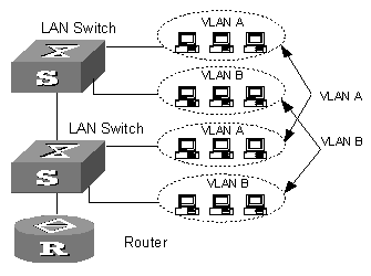
Figure 1-1 A VLAN implementation
A VLAN can span across multiple switches, or even routers. This enables hosts in a VLAN to be dispersed in a looser way. That is, hosts in a VLAN can belong to different physical network segment.
Compared with the traditional Ethernet, VLAN enjoys the following advantages.
l Broadcasts are confined to VLANs. This decreases bandwidth utilization and improves network performance.
l Network security is improved. VLANs cannot communicate with each other directly. That is, a host in a VLAN cannot access resources in another VLAN directly, unless routers or Layer 3 switches are used.
l Network configuration workload for the host is reduced. VLAN can be used to group specific hosts. When the physical position of a host changes within the range of the VLAN, you need not change its network configuration.
1.1.2 VLAN Principles
VLAN tags in the packets are necessary for the switch to identify packets of different VLANs. The switch works at Layer 2 (Layer 3 switches are not discussed in this chapter) and it can identify the data link layer encapsulation of the packet only, so you can add the VLAN tag field into only the data link layer encapsulation if necessary.
In 1999, IEEE issues the IEEE 802.1Q protocol to standardize VLAN implementation, defining the structure of VLAN-tagged packets.
In traditional Ethernet data frames, the type field of the upper layer protocol is encapsulated after the destination MAC address and source MAC address, as shown in Figure 1-2
![]()
Figure 1-2 Encapsulation format of traditional Ethernet frames
In Figure 1-2 DA refers to the destination MAC address, SA refers to the source MAC address, and Type refers to the protocol type of the packet. IEEE 802.1Q protocol defines that a 4-byte VLAN tag is encapsulated after the destination MAC address and source MAC address to show the information about VLAN.
![]()
As shown in Figure 1-3, a VLAN tag contains four fields, including TPID, priority, CFI, and VLAN ID.
l TPID is a 16-bit field, indicating that this data frame is VLAN-tagged. By default, it is 0x8100 in H3C series Ethernet switches.
l Priority is a 3-bit field, referring to 802.1p priority. Refer to section “QoS & QoS profile” for details.
l CFI is a 1-bit field, indicating whether the MAC address is encapsulated in the standard format in different transmission media. This field is not described in detail in this chapter.
l VLAN ID is a 12-bit field, indicating the ID of the VLAN to which this packet belongs. It is in the range of 0 to 4,095. Generally, 0 and 4,095 is not used, so the field is in the range of 1 to 4,094.
VLAN ID identifies the VLAN to which a packet belongs. When the switch receives a packet carrying no VLAN tag, it will encapsulate a VLAN tag with the default VLAN ID of the inbound port for the packet, and the packet will be assigned to the default VLAN of the inbound port for transmission. For the details about setting the default VLAN of a port, refer to section “Port Basic Configuration” in H3C S3600 Series Ethernet Switches Operation Manual.
1.2 Port-Based VLAN
Port-based VLAN technology introduces the simplest way to classify VLANs. You can isolate the hosts and divide them into different virtual workgroups through assigning the ports on the device connecting to hosts to different VLANs.
This way is easy to implement and manage and it is applicable to hosts with relatively fixed positions.
1.3 Protocol-Based VLAN
1.3.1 Introduction to Protocol-Based VLAN
Protocol-based VLAN is also known as protocol VLAN, which is another way to classify VLANs besides port-based VLAN. Through the protocol-based VLANs, the switch can analyze the received packets carrying no VLAN tag on the port and match the packets with the user-defined protocol template automatically according to different encapsulation formats and the values of the special fields. If a packet is matched, the switch will add a corresponding VLAN tag to it automatically. Thus, the data of the specific protocol is assigned automatically to the corresponding VLAN for transmission.
This feature is used for binding the ToS provided in the network to VLAN to facilitate management and maintenance.
1.3.2 Encapsulation Format of Ethernet Data
This section introduces the common encapsulation formats of Ethernet data for you to understand well the procedure for the switch to identify the packet protocols.
I. Ethernet II and 802.2/802.3 encapsulation
In the link layer, there are two main packet encapsulation types: Ethernet II and 802.2/802.3, whose encapsulation formats are described in the following figures.
Ethernet II packet:
![]()
Figure 1-4 Ethernet II encapsulation format
802.2/802.3 packet:
![]()
Figure 1-5 802.2/802.3 encapsulation format
In the two figures, DA and SA refer to the destination MAC address and source MAC address of the packet respectively. The number in the bracket indicates the field length in bits.
The maximum length of an Ethernet packet is 1500 bytes, that is, 5DC in hexadecimal, so the length field in 802.2/802.3 encapsulation is in the range of 0x0000 to 0x05DC.
Whereas, the type field in Ethernet II encapsulation is in the range of 0x0600 to 0xFFFF.
& Notes:
Presently, H3C S3600 series switches recognize packets with the value of the type field being in the range 0x05DD to 0x05FF as 802.2/802.3 encapsulated packets.
The switch identifies whether a packet is an Ethernet II packet or an 802.2/802.3 packet according to the ranges of the two fields.
II. Encapsulation formats of 802.2/802.3 packets
802.2/802.3 packets are encapsulated in the following three formats:
l 802.3 raw encapsulation: only the length field is encapsulated after the source and destination address field, followed by the upper layer data. The type field is not included.
![]()
Figure 1-6 802.3 raw encapsulation format
Only the IPX protocol supports 802.3 raw encapsulation format currently. This format is identified by the two bytes whose value is 0xFFFF after the length field.
l 802.2 logical link control (LLC) encapsulation: the length field, the destination service access point (DSAP) field, the source service access point (SSAP) field and the control field are encapsulated after the source and destination address field.
![]()
Figure 1-7 802.2 LLC encapsulation format
The DSAP field and the SSAP field in the LLC part are used to identify the upper layer protocol. For example, the two fields are both 0xE0, meaning that the upper layer protocol is IPX protocol.
l 802.2 sub-network access protocol (SNAP) encapsulation: the length field, the DSAP filed, the SSAP field, the control field, the OUI field and the PID field are encapsulated according to 802.2/802.3 packets.
![]()
Figure 1-8 802.2 SNAP encapsulation format
In 802.2 SNAP encapsulation format, the values of the DSAP field and the SSAP field are always AA, and the value of the control field is always 3.
The switch differentiates between 802.2 LLC encapsulation and 802.2 SNAP encapsulation according to the values of the DSAP field and the SSAP field.
& Note:
When the OUI is 00-00-00 in 802.2 SNAP encapsulation, the PID field has the same meaning as the type field in Ethernet II encapsulation, which both refer to globally unique protocol number. Such encapsulation is also known as SNAP RFC1042 encapsulation, which is standard SNAP encapsulation. The SNAP encapsulation mentioned in this chapter refers to SNAP RFC 1042 encapsulation.
1.3.3 Procedure for the Switch to Judge Packet Protocol
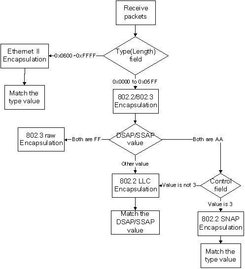
Figure 1-9 Procedure for the switch to judge packet protocol
1.3.4 Encapsulation Formats
Table 1-1 Encapsulation formats
|
Encapsulation
Protocol |
Ethernet II |
802.3 raw |
802.2 LLC |
802.2 SNAP |
Type value |
|
IP |
Supported |
Not supported |
Not supported |
Supported |
0x0800 |
|
IPX |
Supported |
Supported |
Supported |
Supported |
0x8137 |
|
AppleTalk |
Supported |
Not supported |
Not supported |
Supported |
0x809B |
1.3.5 Implementation of Protocol-Based VLAN
S3600 series Ethernet switches assign the packet to the specific VLAN by matching the packet with the protocol template.
The protocol template is the standard to determine the protocol to which a packet belongs. Protocol templates include standard templates and user-defined templates:
l The standard template adopts the RFC-defined packet encapsulation formats and values of some specific fields as the matching criteria.
l The user-defined template adopts the user-defined encapsulation formats and values of some specific fields as the matching criteria.
After configuring the protocol template, you must add a port to the protocol-based VLAN and associate this port with the protocol template. This port will add VLAN tags to the packets based on protocol types. The port in the protocol-based VLAN must be connected to a client. However, a common client cannot process VLAN-tagged packets. In order that the client can process the packets out of this port, you must configure the port in the protocol-based VLAN as a hybrid port and configure the port to remove VLAN tags when forwarding packets of all VLANs.
& Note:
For the operation of removing VLAN tags when the hybrid port sends packets, refer to the section “Port Basic Configuration” in this manual.
Chapter 2 VLAN Configuration
2.1 VLAN Configuration
2.1.1 Basic VLAN Configuration
Table 2-1 Basic VLAN configuration
|
Operation |
Command |
Description |
|
Enter system view |
system-view |
— |
|
Create multiple VLANs in batch |
vlan { vlan-id1 to vlan-id2 | all } |
Optional |
|
Create a VLAN and enter VLAN view |
vlan vlan-id |
Required The vlan-id argument ranges from 1 to 4,094. |
|
Assign a name for the current VLAN |
name text |
Optional By default, the name of a VLAN is its VLAN ID. |
|
Specify the description string of the current VLAN |
description text |
Optional By default, the description string of a VLAN is its VLAN ID. |
![]() Caution:
Caution:
When you use the vlan command to create VLANs, if the destination VLAN is an existing dynamic VLAN, it will be transformed into a static VLAN and the switch will output the prompt information.
2.1.2 Basic VLAN Interface Configuration
I. Configuration prerequisites
Create a VLAN before configuring a VLAN interface.
II. Configuration procedure
Table 2-2 Basic VLAN interface configuration
|
Operation |
Command |
Description |
|
Enter system view |
system-view |
— |
|
Create a VLAN interface and enter VLAN interface view |
interface Vlan-interface vlan-id |
Required The vlan-id argument ranges from 1 to 4,094. |
|
Specify the description string for the current VLAN interface |
description text |
Optional By default, the description string of a VLAN interface is the name of this VLAN interface |
|
Disable the VLAN interface |
shutdown |
Optional |
|
Enable the VLAN Interface |
undo shutdown |
Optional |
Note that the operation of enabling/disabling a VLAN interface does not influence the enabling/disabling states of the Ethernet ports belonging to this VLAN.
By default, the VLAN interface’s management state is enabled. In this case, the physical state of the VLAN interface is affected by the ports state in the VLAN. When all the Ethernet ports of a VLAN are down, the VLAN interface of the VLAN is down, that is, the VLAN interface is disabled; when one or more Ethernet ports of a VLAN are up, the VLAN interface of the VLAN is up, that is, the VLAN interface is enabled.
If you disable the VLAN interface’s management state, the VLAN interface will always be down, regardless of the states of the ports in the VLAN.
2.1.3 Displaying VLAN Configuration
After the configuration above, you can execute the display command in any view to display the running status after the configuration, so as to verify the configuration.
Table 2-3 Display VLAN configuration
|
Operation |
Command |
Description |
|
Display the VLAN interface information |
display interface Vlan-interface [ vlan-id ] |
You can execute the display command in any view. |
|
Display the VLAN information |
display vlan [ vlan-id [ to vlan-id ] | all | dynamic | static ] |
2.2 Configuring a Port-Based VLAN
2.2.1 Configuring a Port-Based VLAN
I. Configuration prerequisites
Create a VLAN before configuring a port-based VLAN.
II. Configuration procedure
Table 2-4 Configure a port-based VLAN
|
Operation |
Command |
Description |
|
Enter system view |
system-view |
— |
|
Enter VLAN view |
vlan vlan-id |
— |
|
Add Ethernet ports to the specific VLAN |
port interface-list |
Required By default, all the ports belong to the default VLAN |
![]() Caution:
Caution:
The commands above are effective for access ports only. If you want to add trunk ports or hybrid ports to a VLAN, you can use the port trunk permit vlan command or the port hybrid vlan command in Ethernet port view. For the configuration procedure, refer to the section "Port Basic Configuration – Operation" in H3C S3600 Series Ethernet Switches Operation Manual.
2.2.2 Protocol-Based VLAN Configuration Example
I. Network requirements
l Create VLAN 2 and VLAN 3 and specify the description string of VLAN 2 as home;
l Add Ethernet1/0/1 and Ethernet1/0/2 to VLAN 2 and add Ethernet1/0/3 and Ethernet1/0/4 to VLAN 3.
II. Network diagram
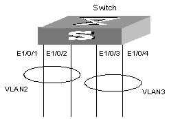
Figure 2-1 Network diagram for VLAN configuration
III. Configuration procedure
# Create VLAN 2 and enter its view.
<H3C> system-view
[H3C] vlan 2
# Specify the description string of VLAN 2 as home.
[H3C-vlan2] description home
# Add Ethernet1/0/1 and Ethernet1/0/2 ports to VLAN 2.
[H3C-vlan2] port Ethernet 1/0/1 Ethernet 1/0/2
# Create VLAN 3 and enter its view.
[H3C-vlan2] vlan 3
# Add Ethernet1/0/3 and Ethernet1/0/4 ports to VLAN 3.
[H3C-vlan3] port Ethernet 1/0/3 Ethernet 1/0/4
2.3 Configuring a Protocol-Based VLAN
2.3.1 Creating Protocol Template for Protocol-Based VLAN
I. Configuration prerequisites
Create a VLAN before configuring a protocol-based VLAN.
II. Configuration procedure
Table 2-5 Create protocol types of VLANs
|
Operation |
Command |
Description |
|
Enter system view |
system-view |
— |
|
Enter VLAN view |
vlan vlan-id |
Required |
|
Create the protocol template for the VLAN |
protocol-vlan [ protocol-index ] { at | ip | ipx { ethernetii | llc | raw | snap } | mode { ethernetii etype etype-id | llc { dsap dsap-id ssap ssap-id } | snap etype etype-id } } |
Required |
When you are creating protocol templates for protocol-based VLANs, the at, ip and ipx keywords are used to create standard templates, and the mode keyword is used to create user-defined templates.
![]() Caution:
Caution:
l Because the IP protocol is closely associated with the ARP protocol, you are recommended to configure the ARP protocol type when configuring the IP protocol type and associate the two protocol types with the same port, in case that ARP packets and IP packets are not assigned to the same VLAN, which will cause IP address resolution failure.
l The mode llc dsap ff ssap ff and ipx raw keywords match the same type of packets, the ipx raw keyword takes precedence over the mode llc dsap ff ssap ff keyword, and a packet will not be further matched if it does not match the ipx raw keyword, therefore, the protocol-vlan mode llc dsap ff ssap ff command takes no effect.
l Packet encapsulation type is snap, instead of llc, if the values of the dsap-id and ssap-id arguments are both AA.
l When you use the mode keyword to configure protocol-based VLANs, if you set the etype-id argument to 0x0800, 0x809b, or 0x8137 for Ethernet II or SNAP packets, the matched packets have the same format as that of IP, IPX, and AppleTalk packets respectively. In order that the two commands do not configure the same protocol repetitively, the switch will prompt that you cannot specify the etype-id argument of Ethernet II and SNAP packets to 0x0800, 0x089b, or 0x8137.
2.3.2 Associating a Port with the Protocol-Based VLAN
I. Configuration prerequisites
l The protocol template for the protocol-based VLAN is created
l The port is configured as a hybrid port, and the port is configured to remove VLAN tags when it forwards the packets of the protocol-based VLANs.
II. Configuration procedure
Table 2-6 Associate a port with the protocol-based VLAN
|
Operation |
Command |
Description |
|
Enter system view |
system-view |
— |
|
Enter port view |
interface interface-type interface-number |
Required |
|
Associate a port with the protocol-based VLAN |
port hybrid protocol-vlan vlan vlan-id { protocol-index [ to protocol-end ] | all } |
Required |
![]() Caution:
Caution:
For the operation of adding a hybrid port to the VLAN, refer to the section “Port Basic Configuration” in this manual.
2.3.3 Displaying Protocol-Based VLAN Configuration
After the configuration above, you can execute the display command in any view to display the running status, so as to verify the configuration.
Table 2-7 Display VLAN configuration
|
Operation |
Command |
Description |
|
Display the information about the protocol-based VLAN |
display vlan [ vlan-id [ to vlan-id ] | all | static | dynamic ] |
You cam execute the display command in any view |
|
Display the protocol information and protocol indexes configured on the specified VLAN |
display protocol-vlan vlan { vlan-id [ to vlan-id ] | all } |
|
|
Display the protocol information and protocol indexes configured on the specified port |
display protocol-vlan interface { interface-type interface-number [ to interface-type interface-number ] | all } |
2.3.4 Protocol-Based VLAN Configuration Example
I. Standard-template-based protocol VLAN configuration example
1) Network requirements
l Create VLAN 5 and configure it to be a protocol-based VLAN, with the protocol-index being 1 and the protocol being IP.
l Associate Ethernet1/0/5 port with the protocol-based VLAN to enable IP packets received by this port to be tagged with the tag of VLAN 5 and be transmitted in VLAN 5.
2) Configuration procedure
# Create VLAN 5 and enter its view.
<H3C> system-view
[H3C] vlan 5
[H3C-vlan5]
# Configure the protocol-index to be 1, and the associated protocol to be IP.
[H3C-vlan5] protocol-vlan 1 ip
# Enter Ethernet1/0/5 port view.
[H3C-vlan5] interface Ethernet 1/0/5
# Configure the port to be a hybrid port.
[H3C-Ethernet1/0/5] port link-type hybrid
# Add the port to VLAN 5 and add VLAN 5 to the untagged VLAN list of the port.
[H3C-Ethernet1/0/5] port hybrid vlan 5 untagged
# Associate the port with protocol-index 1.
[H3C-Ethernet1/0/5] port hybrid protocol-vlan vlan 5 1
II. User-defined-template-based protocol VLAN configuration example
1) Network requirement
l Create VLAN 7 and configure it as a protocol-based VLAN.
l Create two indexes in VLAN 7. Index 1 is used to match the packets with DSAP and SSAP value being 01 and ac respectively in 802.2 LLC encapsulation; Index 2 is used to match the packets with the type value being 0xabcd in 802.2 SNAP encapsulation.
l Associate Ethernet1/0/7 port with the two indexes of the protocol-based VLAN 7 to enable IP packets matching one of the indexes received by this port to be tagged with the tag of VLAN 7.
2) Configuration procedure
# Create VLAN 7 and enter its view.
<H3C> system-view
[H3C] vlan 7
[H3C-vlan7]
# Configure index 1 of VLAN 7 according to the network requirement.
[H3C-vlan7] protocol-vlan 1 mode llc dsap 01 ssap ac
# Configure index 2 of VLAN 7 according to the network requirement.
[H3C-vlan7] protocol-vlan 2 mode snap etype abcd
# Enter port view of the Ethernet1/0/7.
[H3C-vlan7] interface Ethernet 1/0/7
# configure the port as a hybird port.
[H3C-Ethernet1/0/7] port link-type hybrid
# Add the port to VLAN 7, and add VLAN 7 to the list of untagged VLANs permitted to pass through the port.
[H3C-Ethernet1/0/7] port hybrid vlan 7 untagged
# Associate the port with the two indexes of VLAN 7.
[H3C-Ethernet1/0/7] port hybrid protocol-vlan vlan 7 1 to 2