- Table of Contents
-
- H3C S3600 Series Ethernet Switches Operation Manual-Release 1510(V1.04)
- 00-1Cover
- 00-2Product Overview
- 01-CLI Operation
- 02-Login Operation
- 03-Configuration File Management Operation
- 04-VLAN Operation
- 05-IP Address and Performance Configuration Operation
- 06-Management VLAN Operation
- 07-Voice VLAN Operation
- 08-GVRP Operation
- 09-Port Basic Configuration Operation
- 10-Link Aggregation Operation
- 11-Port Isolation Operation
- 12-Port Security-Port Binding Operation
- 13-DLDP Operation
- 14-MAC Address Table Operation
- 15-Auto Detect Operation
- 16-MSTP Operation
- 17-Routing Protocol Operation
- 18-Multicast Operation
- 19-802.1x Operation
- 20-AAA-RADIUS-HWTACACS-EAD Operation
- 21-VRRP Operation
- 22-Centralized MAC Address Authentication Operation
- 23-ARP Operation
- 24-DHCP Operation
- 25-ACL Operation
- 26-QoS-QoS Profile Operation
- 27-Web Cache Redirection Operation
- 28-Mirroring Operation
- 29-IRF Fabric Operation
- 30-Cluster Operation
- 31-PoE-PoE Profile Operation
- 32-UDP Helper Operation
- 33-SNMP-RMON Operation
- 34-NTP Operation
- 35-SSH Terminal Service Operation
- 36-File System Management Operation
- 37-FTP and TFTP Operation
- 38-Information Center Operation
- 39-System Maintenance and Debugging Operation
- 40-VLAN-VPN Operation
- 41-HWPing Operation
- 42-DNS Operation
- 43-Access Management Operation
- 44-Appendix
- Related Documents
-
| Title | Size | Download |
|---|---|---|
| 09-Port Basic Configuration Operation | 103 KB |
Chapter 1 Port Basic Configuration
1.1.1 Types and Numbers of Ethernet Ports
1.1.2 Link Types of Ethernet Ports
1.1.3 Configuring the Default VLAN ID for an Ethernet Port
1.1.4 Adding an Ethernet Port to Specified VLANs
1.2 Ethernet Port Configuration
1.2.1 Initially Configuring a Port
1.2.2 Limiting Traffic on individual Ports
1.2.3 Enabling Flow Control on a Port
1.2.4 Configuring Access Port Attribute
1.2.5 Configuring Hybrid Port Attribute
1.2.6 Configuring Trunk Port Attribute
1.2.7 Copying the Configuration of a Port to Other Ports
1.2.8 Configuring Loopback Detection for an Ethernet Port
1.2.9 Configuring the Ethernet Port to Run Loopback Test
1.2.10 Enabling the System to Test Connected Cable
1.2.11 Configuring the Interval to Perform Statistical Analysis on Port Traffic
1.2.12 Enabling Giant-Frame Statistics Function
1.2.13 Displaying Basic Port Configuration
1.3 Ethernet Port Configuration Example
1.4 Troubleshooting Ethernet Port Configuration
Chapter 1 Port Basic Configuration
1.1 Ethernet Port Overview
1.1.1 Types and Numbers of Ethernet Ports
Table 1-1 lists the types and numbers of the ports available on the H3C S3600 series Ethernet switches.
Table 1-1 Models in the S3600 series
|
Model |
Number of service ports |
Number of 100 Mbps ports |
Number of 1000 Mbps uplink ports |
Console port |
|
H3C S3600-28P-SI |
28 |
24 10/100 Mbps (electrical) |
4 (SFP) |
1 |
|
H3C S3600-28P-PWR-SI |
28 |
24 10/100 Mbps (electrical) |
4 (SFP) |
1 |
|
H3C S3600-28TP-SI |
28 |
24 10/100 Mbps (electrical) |
2 (SFP) 2 10/100/1000 Mbps (electrical) |
1 |
|
H3C S3600-52P-SI |
52 |
48 10/100 Mbps (electrical) |
4 (SFP) |
1 |
|
H3C S3600-28P-EI |
28 |
24 10/100 Mbps (electrical) |
4 (SFP) |
1 |
|
H3C S3600-28F-EI |
28 |
24 100 Mbps (SFP) |
2 (SFP) 2 10/100/1000 Mbps (electrical) |
1 |
|
H3C S3600-28P-PWR-EI |
28 |
24 10/100 Mbps (electrical) |
4 (SFP) |
1 |
|
H3C S3600-52P-EI |
52 |
48 10/100 Mbps (electrical) |
4 (SFP) |
1 |
|
H3C S3600-52P-PWR-EI |
52 |
48 10/100 Mbps (electrical) |
4 (SFP) |
1 |
|
H3C S3600-52P-PWR-SI |
52 |
48 10/100 Mbps (electrical) |
4 (SFP) |
1 |
1.1.2 Link Types of Ethernet Ports
An Ethernet port on an S3600 switch can operate in one of the three link types:
l Access: An access port can belong to only one VLAN, and is generally used to connect user PCs.
l Trunk: A trunk port can belong to more than one VLAN. It can receive/send packets from/to multiple VLANs, and is generally used to connect another switch.
l Hybrid: A hybrid port can belong to more than one VLAN. It can receive/send packets from/to multiple VLANs, and can be used to connect either a switch or user PCs.
& Note:
A hybrid port allows the packets of multiple VLANs to be sent without tags, but a trunk port only allows the packets of the default VLAN to be sent without tags.
You can configure all the three types of ports on the same device. However, note that you cannot directly switch a port between trunk and hybrid and you must set the port as access before the switching. For example, to change a trunk port to hybrid, you must first set it as access and then hybrid.
1.1.3 Configuring the Default VLAN ID for an Ethernet Port
An access port can belong to only one VLAN. Therefore, the VLAN an access port belongs to is also the default VLAN of the access port. A hybrid/trunk port can belong to several VLANs, and so a default VLAN ID for the port is required.
After you configure default VLAN IDs for Ethernet ports, the packets passing through the ports are processed in different ways depending on different situations. See Table 1-2 for details.
Table 1-2 Processing of incoming/outgoing packets
|
Port type |
Processing of an incoming packet |
Processing of an outgoing packet |
|
|
If the packet does not carry a VLAN tag |
If the packet carries a VLAN tag |
||
|
Access |
Receive the packet and add the default tag to the packet. |
l If the VLAN ID is just the default VLAN ID, receive the packet. l If the VLAN ID is not the default VLAN ID, discard the packet. |
Deprive the tag from the packet and send the packet. |
|
Trunk |
l If the VLAN ID is just the default VLAN ID, receive the packet. l If the VLAN ID is not the default VLAN ID but is one of the VLAN IDs allowed to pass through the port, receive the packet. l If the VLAN ID is neither the default VLAN ID, nor one of the VLAN IDs allowed to pass through the port, discard the packet. |
l If the VLAN ID is just the default VLAN ID, deprive the tag and send the packet. l If the VLAN ID is not the default VLAN ID, keep the original tag unchanged and send the packet. |
|
|
Hybrid |
Send the packet if the VLAN ID is allowed to pass through the port. Use the port hybrid vlan command to configure whether the port tags the packet when sending a packet in this VLAN (including default VLAN). |
||
![]() Caution:
Caution:
You are recommended to set the default VLAN ID of the local hybrid or trunk ports to the same value as that of the hybrid or trunk ports on the peer switch. Otherwise, packet forwarding may fail on the ports.
1.1.4 Adding an Ethernet Port to Specified VLANs
You can add the specified Ethernet port to a specified VLAN. After that, the Ethernet port can forward the packets of the specified VLAN, so that the VLAN on this switch can intercommunicate with the same VLAN on the peer switch.
An access port can only be added to one VLAN, while hybrid and trunk ports can be added to multiple VLANs.
& Note:
The access ports or hybrid ports must be added to an existing VLAN.
1.2 Ethernet Port Configuration
1.2.1 Initially Configuring a Port
Table 1-3 Initially configure a port
|
Operation |
Command |
Remarks |
|
Enter system view |
system-view |
— |
|
Enter Ethernet port view |
interface interface-type interface-number |
— |
|
Enable the Ethernet port |
undo shutdown |
Optional By default, the port is enabled. Use the shutdown command to disable the port. |
|
Set the description of the Ethernet port |
description text |
Optional By default, no description is defined for the port. |
|
Set the duplex mode of the Ethernet port |
duplex { auto | full | half } |
Optional By default, the duplex mode of the port is auto (auto-negotiation). |
|
Set the speed of the Ethernet port |
speed { 10 | 100 | 1000 | auto } |
Optional By default, the speed of the port is auto (auto-negotiation). |
|
Set the medium dependent interface (MDI) attribute of the Ethernet port |
mdi { across | auto | normal } |
Optional Be default, the MDI attribute of the port is auto. |
|
Allow jumbo frames that are not larger than 9216 bytes to pass through the Ethernet port |
jumboframe enable |
Optional By default, jumbo frames that are not larger than 9216 bytes are allowed to pass through the port. |
1.2.2 Limiting Traffic on individual Ports
By performing the following configurations, you can limit different types of incoming traffic on individual ports. When a type of incoming traffic exceeds the threshold you set, the system drops the packets exceeding the traffic limit to reduce the traffic ratio of this type to the reasonable range, so as to keep normal network service.
Table 1-4 Limit traffic on port
|
Operation |
Command |
Remarks |
|
Enter system view |
system-view |
— |
|
Limit broadcast traffic received on each port |
broadcast-suppression { ratio | pps max-pps } |
Optional By default, the switch does not suppress broadcast traffic. |
|
Enter Ethernet port view |
interface interface-type interface-number |
— |
|
Limit broadcast traffic received on the current port |
broadcast-suppression { ratio | pps max-pps } |
Optional By default, the switch does not suppress broadcast traffic. |
|
Limit multicast traffic received on the current port |
multicast-suppression { ratio | pps max-pps } |
Optional By default, the switch does not suppress multicast traffic. |
|
Limit unknown unicast traffic received on the current port |
unicast-suppression { ratio | pps max-pps } |
Optional By default, the switch does not suppress unknown unicast traffic. |
1.2.3 Enabling Flow Control on a Port
Flow control is enabled on both the local and peer switches. If congestion occurs on the local switch:
l The local switch sends a message to notify the peer switch of stopping sending packets to itself or reducing the sending rate temporarily.
l The peer switch will stop sending packets to the local switch or reduce the sending rate temporarily when it receives the message; and vice versa. By this way, packet loss is avoided and the network service operates normally.
Table 1-5 Enable flow control on a port
|
Operation |
Command |
Remarks |
|
Enter system view |
system-view |
— |
|
Enter Ethernet port view |
interface interface-type interface-number |
— |
|
Enable flow control on the Ethernet port |
flow-control |
By default, flow control is not enabled on the port. |
1.2.4 Configuring Access Port Attribute
Table 1-6 Configure access port attribute
|
Operation |
Command |
Remarks |
|
Enter system view |
system-view |
— |
|
Enter Ethernet port view |
interface interface-type interface-number |
— |
|
Set the link type of the port to access |
port link-type access |
Optional By default, the link type of a port is access. |
|
Add the current access port to a specified VLAN |
port access vlan vlan-id |
Optional |
1.2.5 Configuring Hybrid Port Attribute
Table 1-7 Configure hybrid port attribute
|
Operation |
Command |
Remarks |
|
Enter system view |
system-view |
— |
|
Enter Ethernet port view |
interface interface-type interface-number |
— |
|
Set the link type of the port to hybrid |
port link-type hybrid |
Required |
|
Set the default VLAN ID for the hybrid port |
port hybrid pvid vlan vlan-id |
Optional If no default VLAN ID is set for a hybrid port, VLAN 1 (system default VLAN) is used as the default VLAN of the port. |
|
Add the current hybrid port to a specified VLAN |
port hybrid vlan vlan-id-list { tagged | untagged } |
Optional For a hybrid port, you can configure whether the system keeps VLAN tags when the packets of the specified VLANs are forwarded on this port. |
1.2.6 Configuring Trunk Port Attribute
Table 1-8 Configure trunk port attribute
|
Operation |
Command |
Remarks |
|
Enter system view |
System-view |
— |
|
Enter Ethernet port view |
interface interface-type interface-number |
— |
|
Set the link type of the port to trunk |
port link-type trunk |
Required |
|
Set the default VLAN ID for the trunk port |
port trunk pvid vlan vlan-id |
Optional If no default VLAN ID is set for a trunk port, VLAN 1 (system default VLAN) is used as the default VLAN of the port. |
|
Add the current trunk port to a specified VLAN |
port trunk permit vlan { vlan-id-list | all } |
Optional |
1.2.7 Copying the Configuration of a Port to Other Ports
To make some other ports have the same configuration as that of a specific port, you can copy the configuration of the specific port to the ports.
Specifically, the following types of port configuration can be copied from one port to other ports: VLAN configuration, protocol-based VLAN configuration, LACP configuration, QoS configuration, GARP configuration, STP configuration and initial port configuration.
l VLAN configuration: includes IDs of the VLANs allowed on the port and the default VLAN ID of the port;
l Protocol-based VLAN configuration: includes IDs and indexes of the protocol-based VLANs allowed on the port;
l Link aggregation control protocol (LACP) configuration: includes LACP enable/disable status;
& Note:
The copy command can only be used to copy the configuration of LACP’s enable state, but not to copy the configuration of aggregation group, i.e., you can not add a port to the aggregation group bye the command.
l QoS configuration: includes rate limit, port priority, and default 802.1p priority on the port;
l STP configuration: includes STP enable/disable status on the port, link attribute on the port (point-to-point or non-point-to-point), STP priority, path cost, packet transmission rate limit, whether loop protection is enabled, whether root protection is enabled, and whether the port is an edge port;
l Generic attribute registration protocol (GARP) configuration: includes GVRP enable/disable status, timer settings, and registration mode;
l Port configuration: includes link type of the port, port rate and duplex mode.
Table 1-9 Copy the configuration of a port to other ports
|
Operation |
Command |
Remarks |
|
Enter system view |
system-view |
— |
|
Copy the configuration of a port to other ports |
copy configuration source { interface-type interface-number | aggregation-group source-agg-id } destination { interface-list [ aggregation-group destination-agg-id ] | aggregation-group destination-agg-id } |
Required |
& Note:
l If you specify a source aggregation group ID, the system will use the port with the smallest port number in the aggregation group as the source.
l If you specify a destination aggregation group ID, the configuration of the source port will be copied to all ports in the aggregation group and all ports in the group will have the same configuration as that of the source port.
1.2.8 Configuring Loopback Detection for an Ethernet Port
Loopback detection is used to monitor if loopback occurs on a switch port.
After you enable loopback detection on Ethernet ports, the switch can monitor if external loopback occurs on them. If there is a loopback port found, the switch will put it under control.
l If loopback is found on an access port, the system disables the port, sends a Trap message to the client and removes the corresponding MAC forwarding entry.
l If loopback is found on a trunk or hybrid port, the system sends a Trap message to the client. When the loopback port control function is enabled on these ports, the system disables the port, sends a Trap message to the client and removes the corresponding MAC forwarding entry.
Table 1-10 Set loopback detection for an Ethernet port
|
Operation |
Command |
Remarks |
|
Enter system view |
system-view |
— |
|
Enable loopback detection globally |
loopback-detection enable |
Optional By default, loopback detection is disabled globally. |
|
Set time interval for port loopback detection |
loopback-detection interval-time time |
Optional The default interval is 30 seconds. |
|
Enter Ethernet port view |
interface interface-type interface-number |
— |
|
Enable loopback detection on a specified port |
loopback-detection enable |
Optional By default, port loopback detection is disabled. |
|
Enable loopback port control on the trunk or hybrid port |
loopback-detection control enable |
Optional By default, loopback port control is not enabled. |
|
Configure the system to run loopback detection on all VLANs of the current trunk or hybrid port |
loopback-detection per-vlan enable |
Optional By default, the system runs loopback detection only on the default VLAN of the current trunk or hybrid port. |
|
Display port loopback detection information |
Optional You can use the command in any view. |
![]() Caution:
Caution:
l To enable loopback detection on a specific port, you must use the loopback-detection enable command in both system view and the specific port view.
l After you use the undo loopback-detection enable command in system view, loopback detection will be disabled on all ports.
1.2.9 Configuring the Ethernet Port to Run Loopback Test
You can configure the Ethernet port to run loopback test to check if it operates normally. The port running loopback test cannot forward data packets normally. The loopback test terminates automatically after a specific period.
Table 1-11 Configure the Ethernet port to run loopback test
|
Operation |
Command |
Remarks |
|
Enter system view |
system-view |
— |
|
Enter Ethernet port view |
interface interface-type interface-number |
— |
|
Configure the Ethernet port to run loopback test |
loopback { external | internal } |
Optional |
& Note:
l external: Performs external loop test. In the external loop test, self-loop headers must be used on the port of the switch ( for 100M port, the self-loop headers are made from four cores of the 8-core cables, for 1000M port, the self-loop header are made from eight cores of the 8-core cables, then the packets forwarded by the port will be received by itself.). The external loop test can locate the hardware failures on the port.
l internal: Performs internal loop test. In the internal loop test, self loop is established in the switching chip to locate the chip failure which is related to the port.
After you use the shutdown command on a port, the port cannot run loopback test. You cannot use the speed, duplex, mdi and shutdown commands on the ports running loopback test. Some ports do not support loopback test, and corresponding prompts will be given when you perform loopback test on them.
1.2.10 Enabling the System to Test Connected Cable
You can enable the system to test the cable connected to a specific port. The test result will be returned in five seconds. The system can test these attributes of the cable: Receive and transmit directions (RX and TX), short circuit/open circuit or not, the length of the faulty cable.
Table 1-12 Enable the system to test connected cables
|
Operation |
Command |
Remarks |
|
Enter system view |
system-view |
— |
|
Enter Ethernet port view |
interface interface-type interface-number |
— |
|
Enable the system to test connected cables |
virtual-cable-test |
Required |
1.2.11 Configuring the Interval to Perform Statistical Analysis on Port Traffic
By performing the following configuration, you can set the interval to perform statistical analysis on the traffic of a port.
When you use the display interface interface-type interface-number command to display the information of a port, the system performs statistical analysis on the traffic flow passing through the port during the specified interval and displays the average rates in the interval. For example, if you set this interval to 100 seconds, the displayed information is as follows:
Last 100 seconds input: 0 packets/sec 0 bytes/sec
Last 100 seconds output: 0 packets/sec 0 bytes/sec
Table 1-13 Set the interval to perform statistical analysis on port traffic
|
Operation |
Command |
Description |
|
Enter system view |
system-view |
— |
|
Enter Ethernet port view |
interface interface-type interface-number |
— |
|
Set the interval to perform statistical analysis on port traffic |
flow-interval interval |
Optional By default, this interval is 300 seconds. |
1.2.12 Enabling Giant-Frame Statistics Function
The giant-frame statistics function is used to ensure transmission of network traffic and to facilitate statistics and analysis of unusual traffic on the network.
Table 1-14 Enable the giant-frame statistics function
|
Operation |
Command |
Description |
|
Enter system view |
system-view |
— |
|
Enable the giant-frame statistics function |
giant-frame statistics enable |
Optional By default, the giant-frame statistics function is not enabled. |
1.2.13 Displaying Basic Port Configuration
After the above configurations, you can execute the display commands in any view to display information about Ethernet ports, so as to verify your configurations.
You can execute the reset counters command in user view to clear the statistics of Ethernet ports.
Table 1-15 Display basic port configuration
|
Operation |
Command |
Remarks |
|
Display port configuration information |
display interface [ interface-type | interface-type interface-number ] |
You can execute the display commands in any view. |
|
Display information about a specified optical port |
display transceiver-information interface interface-type interface-number |
|
|
Display the enable/disable status of port loopback detection |
display loopback-detection |
|
|
Display brief information about port configuration |
display brief interface [ interface-type interface-number ] [ | { begin | include | exclude } string ] |
|
|
Display the hybrid or trunk ports |
display port { hybrid | trunk } |
|
|
Display port information about a specified unit |
display unit unit-id interface |
|
|
Clear port statistics |
reset counters interface [ interface-type | interface-type interface-number ] |
You can execute the reset command in user view. After 802.1x is enabled on a port, clearing the statistics on the port will not work. |
1.3 Ethernet Port Configuration Example
I. Network requirements
l Switch A and Switch B are connected to each other through two trunk port (Ethernet1/0/1).
l Configure the default VLAN ID of both Ethernet1/0/1 to 100.
l Allow the packets of VLAN 2, VLAN 6 through VLAN 50 and VLAN 100 to pass both Ethernet1/0/1.
II. Network diagram
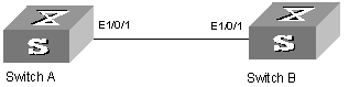
Figure 1-1 Network diagram for Ethernet port configuration
III. Configuration procedure
& Note:
l Only the configuration for Switch A is listed below. The configuration for Switch B is similar to that of Switch A.
l This example supposes that VLAN 2, VLAN 6 through VLAN 50 and VLAN 100 have been created.
# Enter Ethernet port view of Ethernet1/0/1.
<H3C> system-view
System View: return to User View with Ctrl+Z.
[H3C] interface ethernet1/0/1
# Set Ethernet1/0/1 as a trunk port.
[H3C-Ethernet1/0/1] port link-type trunk
# Allow packets of VLAN 2, VLAN 6 through VLAN 50 and VLAN 100 to pass Ethernet1/0/1.
[H3C-Ethernet1/0/1] port trunk permit vlan 2 6 to 50 100
# Configure the default VLAN ID of Ethernet1/0/1 to 100.
[H3C-Ethernet1/0/1] port trunk pvid vlan 100
1.4 Troubleshooting Ethernet Port Configuration
Symptom: Fail to configure the default VLAN ID of a port.
Solution: Take the following steps.
l Use the display interface or display port command to check if the port is a trunk port or a hybrid port. If not, configure it to a trunk port or a hybrid port.
l Configure the default VLAN ID.