- Table of Contents
-
- H3C S3600 Series Ethernet Switches Operation Manual-Release 1510(V1.04)
- 00-1Cover
- 00-2Product Overview
- 01-CLI Operation
- 02-Login Operation
- 03-Configuration File Management Operation
- 04-VLAN Operation
- 05-IP Address and Performance Configuration Operation
- 06-Management VLAN Operation
- 07-Voice VLAN Operation
- 08-GVRP Operation
- 09-Port Basic Configuration Operation
- 10-Link Aggregation Operation
- 11-Port Isolation Operation
- 12-Port Security-Port Binding Operation
- 13-DLDP Operation
- 14-MAC Address Table Operation
- 15-Auto Detect Operation
- 16-MSTP Operation
- 17-Routing Protocol Operation
- 18-Multicast Operation
- 19-802.1x Operation
- 20-AAA-RADIUS-HWTACACS-EAD Operation
- 21-VRRP Operation
- 22-Centralized MAC Address Authentication Operation
- 23-ARP Operation
- 24-DHCP Operation
- 25-ACL Operation
- 26-QoS-QoS Profile Operation
- 27-Web Cache Redirection Operation
- 28-Mirroring Operation
- 29-IRF Fabric Operation
- 30-Cluster Operation
- 31-PoE-PoE Profile Operation
- 32-UDP Helper Operation
- 33-SNMP-RMON Operation
- 34-NTP Operation
- 35-SSH Terminal Service Operation
- 36-File System Management Operation
- 37-FTP and TFTP Operation
- 38-Information Center Operation
- 39-System Maintenance and Debugging Operation
- 40-VLAN-VPN Operation
- 41-HWPing Operation
- 42-DNS Operation
- 43-Access Management Operation
- 44-Appendix
- Related Documents
-
| Title | Size | Download |
|---|---|---|
| 43-Access Management Operation | 237 KB |
Table of Contents
Chapter 1 Access Management Configuration
1.1 Access Management Overview
1.2 Configure Access Management
1.2.1 Enable Access Management Function
1.2.2 Configure the Access IP Address Pool Based on the Physical Port
1.2.3 Configure Layer 2 Isolation between Ports
1.2.4 Enable Access Management Trap
1.4 Access Management Configuration Example
Chapter 1 Access Management Configuration
1.1 Access Management Overview
One of the typical Ethernet access networking scenario is that the users access external network through the Ethernet switches. In this case, the external network is connected to the Ethernet switch. The Ethernet switch connects to the Hubs, each of which centralizes several PCs. The following figure illustrates the networking scenario.
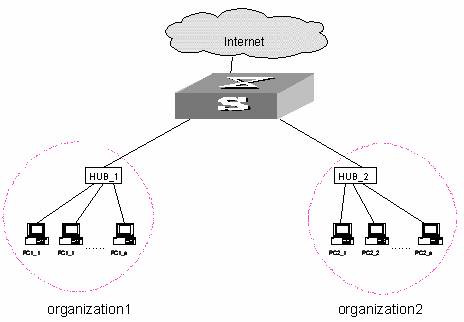
Figure 1-1 Typical Ethernet access networking scenario
If not-so-many users are connected to the switch, the ports allocated to different enterprises need to belong to the same VLAN in the light of cost. Every enterprise is allocated to the fixed IP address range simultaneously. Only those IP addresses in the fixed IP address range can be accessed to external networks from the port. Different organizations should be isolated considering security. All these requirements can be achieved with the access management function by the Ethernet switches, specifically, binding a port with IP addresses and L2 isolation between ports. See Figure 1-1.
In the figure, organization 1 and organization 2 belong to the same VLAN, which are connected to the external networks via an Ethernet switch. The IP addresses 202.10.20.1 ~ 202.10.20.20 are allocated to organization 1, that is, they are bound to the port 1. On the PCs with IP addresses in this range can be connected to external networks. The IP addresses 202.10.20.21 ~ 202.10.20.50 are allocated to organization 2, or bound to the port 2.
Isolation measure is required, because otherwise the PCs in two organizations may interwork with each other. The L2 isolation function at the switch port can ensure two ports do not receive the packets from the other port, so that only those PCs in the same organization can communicate with each other.
1.2 Configure Access Management
Access management configuration includes:
l Enable access management function
l Configure the access IP address pool based on the physical port
l Configure Layer 2 isolation between ports
l Enable access management trap
1.2.1 Enable Access Management Function
You can use the following command to enable access management function. Only after the access management function is enabled globally will the access management features (IP and port binding) take effect.
Table 1-1 Enable access management function
|
Operation |
Command |
Description |
|
Enter system view |
system-view |
— |
|
Enable access management function |
am enable |
Required By default, the system disables the access management function. |
1.2.2 Configure the Access IP Address Pool Based on the Physical Port
You can use the following command to set the IP address pool for access management on a port. The packet whose source IP address is in the specified pool is allowed to be forwarded on Layer 3 via the port of the switch.
Table 1-2 Configure the access IP address pool based on the physical port
|
Operation |
Command |
Description |
|
Enter system view |
system-view |
— |
|
Enter Ethernet port view |
interface interface-type interface-number |
— |
|
Configure the access management IP address pool based on the physical port |
am ip-pool address-list |
Required By default, the IP address pools for access control on the port are null and all the packets are permitted through. |
& Note:
l Before you configure the access management IP address pool on a port, make sure you configure the IP address of the Layer 3 interface to which the port belongs and these two addresses must be on the same network segment.
l If the IP address pool to be configured contains the IP addresses configured in the static ARP at other ports, then the system prompts you to delete the static ARP to make the later binding effective.
1.2.3 Configure Layer 2 Isolation between Ports
Table 1-3lists the operations to add an Ethernet port to an isolation group to isolate Layer 2 data between each port in the isolation group. See the Port Isolation module for the principles and detailed configurations of port isolation.
Table 1-3 Configure port isolation
|
Operation |
Command |
Description |
|
Enter system view |
system-view |
— |
|
Enter Ethernet port view |
interface interface-type interface-number |
— |
|
Add the Ethernet port to the isolation group |
port isolate |
Required By default, an isolation group contains no port |
Note that:
1) One unit only supports one isolation group. That is, a port in an isolation group on a unit is isolated only from ports within this group, while not isolated from ports in isolation groups on other units.
2) The port isolation feature is synchronous on the same unit within an aggregation group, see the following details:
l When a port in an aggregation group is added in or removed from an isolation group, then all the other ports of this aggregation group on the same unit are automatically added in or removed from this isolation group.
l In the same aggregation group, the port isolation feature on one unit is consistent.
l A port is removed from an aggregation group with its isolation feature not change.
l If a port of an aggregation group is isolated on unit 1, then you can achieve the port-to-port isolation between this aggregation group and all the ports of the isolation group on unit 1.
l If all the ports on unit 1 of this aggregation group are removed from this aggregation group, then the isolation feature of this aggregation group is disabled, that is, the port-to-port isolation mentioned above is unavailable.
1.2.4 Enable Access Management Trap
You can use the following command to enable access management trap.
Table 1-4 Enable access management trap
|
Operation |
Command |
Description |
|
Enter system view |
system-view |
— |
|
Enable access management trap |
am trap enable |
Required By default, the access management trap is disabled |
1.3 Display Access Management
After the above configuration, execute display command in any view to display the current configurations of access management on the ports, and to verify the effect of the configuration.
Table 1-5 Display current configuration of access management
|
Operation |
Command |
Description |
|
Display current configuration of access management |
display am [ interface-list ] |
Execute these commands in any view. |
|
Display information about the Ethernet ports added to the isolation group |
display isolate port |
1.4 Access Management Configuration Example
I. Networking requirements
Organization 1 is connected to the port 1 of the switch, and organization 2 to the port 2. The ports 1 and 2 belong to the same VLAN. The IP addresses ranging 202.10.20.1~202.10.20.20 can be accessed from the port 1 and those ranging 202.10.20.21~202.10.20.50 from the port 2. Organization 1 and organization 2 cannot communicate with each other.
II. Networking diagram
See Figure 1-1.
III. Configuration procedure
# Enable access management.
<H3C> system-view
System View: return to User View with Ctrl+Z.
[H3C] am enable
# Configures the IP address pool for access management on port 1.
[H3C] interface ethernet1/0/1
[H3C-Ethernet1/0/1] am ip-pool 202.10.20.1 20
# Add Ethernet1/0/1 to the isolation group.
[H3C-Ethernet1/0/1] port isolate
# Configures the IP address pool for access management on port 2.
[H3C-Ethernet1/0/1] quit
[H3C] interface ethernet1/0/2
[H3C-Ethernet1/0/2] am ip-pool 202.10.20.21 30
# Add Ethernet1/0/2 to the isolation group.
[H3C-Ethernet1/0/2] port isolate