- 产品与解决方案
- 行业解决方案
- 服务
- 支持
- 合作伙伴
- 关于我们


05-三层组播支持M-LAG典型配置举例
本章节下载: 05-三层组播支持M-LAG典型配置举例 (337.20 KB)
本文档介绍了三层组播支持M-LAG(组播源在M-LAG系统侧)和IPv6三层组播支持M-LAG(组播源在M-LAG系统侧)的配置举例。
PIM/IPv6利用M-LAG(Multichassis link aggregation,跨设备链路聚合)功能将两台物理设备连接起来虚拟成一台设备,使用该虚拟设备连接组播源或组播接收者,可避免单点故障对组播网络造成影响,提高组播网络可靠性。
本文档中的配置均是在实验室环境下进行的配置和验证,配置前设备的所有参数均采用出厂时的缺省配置。如果您已经对设备进行了配置,为了保证配置效果,请确认现有配置和以下举例中的配置不冲突。
本文假设您已了解三层组播支持M-LAG特性。
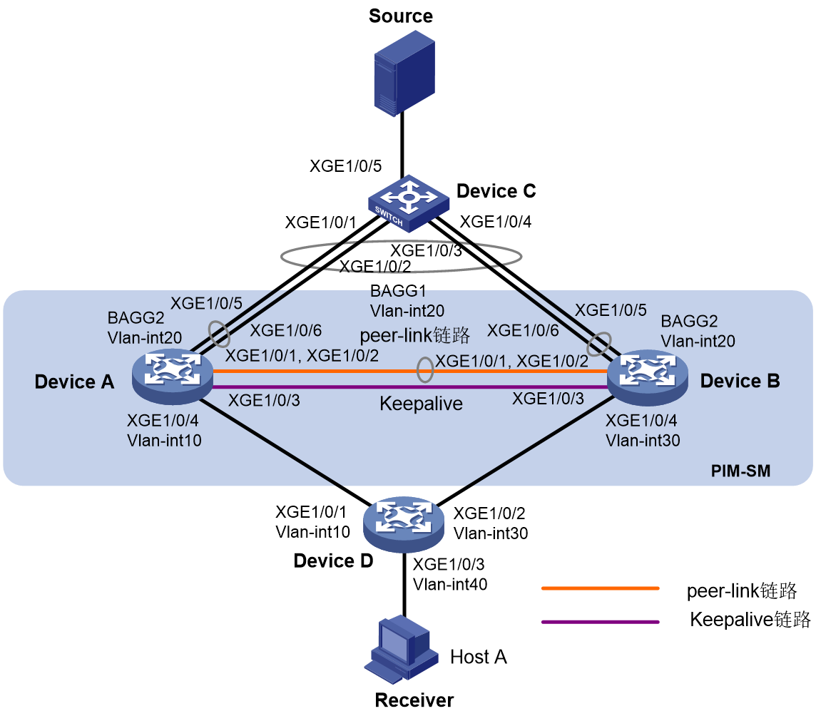
· 网络中运行OSPF协议,接收者通过组播方式接收视频点播信息,不同组织的接收者群体组成末梢网络,每个末梢网络中都存在至少一个接收者,整个PIM域采用SM非管理域方式。
· DeviceC作为二层设备,通过接口Ten-GigabitEthernet1/0/5与组播源互联,通过聚合口1与Device A和Device B形成的M-LAG系统互联。组播源发送的组播数据流量,通过Device C的聚合口进行负载分担,发送到Device A和Device B的M-LAG接口上。Device A和Device B上的Vlan-interface20接口上配置的IP地址作为组播源接入M-LAG系统的网关地址。组播接收者Host A通过Device D接入M-LAG系统。
· 配置Device A和Device B的三层以太网接口Ten-GigabitEthernet1/0/3为保留接口,在该三层以太网接口上搭建Keepalive链路,保证Keepalive报文能够正常传输。
· 在Device A的Vlan-interface 20接口上配置VRRP,设置Device A在备份组1中的优先级为200,以保证Device A成为Master,从而与Device A在M-LAG中角色一致。
· Device A和Device B的M-LAG接口上,允许VLAN 20通过,并在各自的Vlan-interface 20接口上配置PIM协议。
· Device A和Device B上使能IP组播路由功能。
图1 三层组播支持M-LAG(组播源在M-LAG系统侧)组网图
|
设备 |
接口 |
IP地址 |
设备 |
接口 |
IP地址 |
|
Device A |
Vlan-int20 |
20.0.0.1/24 |
Device D |
Vlan-int10 |
100.0.0.2/24 |
|
|
XGE1/0/3 |
200.0.0.1/24 |
|
Vlan-int30 |
30.0.0.2/24 |
|
|
Vlan-int10 |
100.0.0.1/24 |
|
Vlan-int40 |
40.0.0.2/24 |
|
|
Loop0 |
1.1.1.1 |
|
|
|
|
Device B |
Vlan-int20 |
20.0.0.2/24 |
|
|
|
|
|
XGE1/0/3 |
200.0.0.2/24 |
|
|
|
|
|
Vlan-int30 |
30.0.0.1/24 |
|
|
|
|
|
Loop0 |
2.2.2.2 |
|
|
|
表1 适用产品及版本
|
产品 |
软件版本 |
|
S12500G-AF系列交换机 |
Release 7639P01及以上版本 |
|
S10500X系列交换机 |
Release 7639P01及以上版本 |
|
S12500-XS系列交换机 |
Release 7639P01及以上版本 |
|
S7600E-X系列交换机 |
Release 7639P01及以上版本 |
|
S7500X-X系列交换机 |
Release 7639P01及以上版本 |
|
S10500系列交换机 |
Release 7639P01及以上版本 |
|
S7600-X系列交换机 |
Release 7639P01及以上版本 |
|
S12500-S系列交换机 |
Release 7639P01及以上版本 |
|
S7500E-X系列交换机 |
Release 7639P01及以上版本 |
|
S7500E系列交换机 |
Release 7639P01及以上版本 |
|
S7500X系列交换机 |
Release 7639P01及以上版本 |
|
S7600系列交换机 |
Release 7639P01及以上版本 |
|
S7000ET系列交换机 |
Release 7639P01及以上版本 |
请按照上图配置各接口的IP地址和子网掩码,并在PIM-SM域内的各交换机上配置OSPF协议,具体配置略。
# 配置M-LAG系统。
<DeviceA> system-view
[DeviceA] m-lag system-mac 1-1-1
[DeviceA] m-lag system-number 1
[DeviceA] m-lag system-priority 123
# 配置Keepalive报文的目的IP地址和源IP地址。
[DeviceA] m-lag keepalive ip destination 200.0.0.2 source 200.0.0.1
# 配置Keepalive链路接口为保留接口。
[DeviceA] m-lag mad exclude interface ten-gigabitethernet 1/0/3
# 创建二层聚合接口1,并配置该接口为动态聚合模式。
[DeviceA] interface bridge-aggregation 1
[DeviceA-Bridge-Aggregation1] link-aggregation mode dynamic
[DeviceA-Bridge-Aggregation1] quit
# 将接口Ten-GigabitEthernet1/0/1和Ten-GigabitEthernet1/0/2加入到聚合组1中。
[DeviceA] interface ten-gigabitethernet 1/0/1
[DeviceA-Ten-GigabitEthernet1/0/1] port link-aggregation group 1
[DeviceA-Ten-GigabitEthernet1/0/1] quit
[DeviceA] interface ten-gigabitethernet 1/0/2
[DeviceA-Ten-GigabitEthernet1/0/2] port link-aggregation group 1
[DeviceA-Ten-GigabitEthernet1/0/2] quit
# 创建二层聚合接口2,并配置该接口为动态聚合模式。
[DeviceA] interface bridge-aggregation 2
[DeviceA-Bridge-Aggregation2] link-aggregation mode dynamic
[DeviceA-Bridge-Aggregation2] quit
# 将接口Ten-GigabitEthernet1/0/5和Ten-GigabitEthernet1/0/6加入到聚合组2中。
[DeviceA] interface ten-gigabitethernet 1/0/5
[DeviceA-Ten-GigabitEthernet1/0/5] port link-aggregation group 2
[DeviceA-Ten-GigabitEthernet1/0/5] quit
[DeviceA] interface ten-gigabitethernet 1/0/6
[DeviceA-Ten-GigabitEthernet1/0/6] port link-aggregation group 2
[DeviceA-Ten-GigabitEthernet1/0/6] quit
# 配置二层聚合接口1为Trunk端口,并允许所有VLAN的报文通过,并配置该接口为peer-link接口。
[DeviceA] interface bridge-aggregation 1
[DeviceA-Bridge-Aggregation1] port link-type trunk
[DeviceA-Bridge-Aggregation1] port trunk permit vlan all
[DeviceA-Bridge-Aggregation1] port m-lag intra-portal-port 1
[DeviceA-Bridge-Aggregation1] quit
# 配置二层聚合接口2为Trunk端口,并允许VLAN 20的报文通过,并配置该接口为M-LAG接口。
[DeviceA] interface bridge-aggregation 2
[DeviceA-Bridge-Aggregation2] port link-type trunk
[DeviceA-Bridge-Aggregation2] port trunk permit vlan 20
[DeviceA-Bridge-Aggregation2] port m-lag group 1
[DeviceA-Bridge-Aggregation2] quit
# 在Vlan-interface 20接口上配置VRRP,设置Device A在备份组1中的优先级为200,以保证Device A成为Master,从而与Device A在M-LAG中角色一致。
[DeviceA] vlan 20
[DeviceA-vlan20] quit
[DeviceA] interface vlan-interface 20
[DeviceA-Vlan-interface20] vrrp vrid 1 virtual-ip 20.0.0.10
[DeviceA-Vlan-interface20] vrrp vrid 1 priority 200
[DeviceA-Vlan-interface20] quit
# 开启IP组播路由,在Vlan-interface10接口上开启IGMP和PIM,并在其它接口上使能PIM-SM。
[DeviceA] multicast routing
[DeviceA-mrib] quit
[DeviceA] interface vlan-interface 10
[DeviceA-Vlan-interface10] igmp enable
[DeviceA-Vlan-interface10] pim sm
[DeviceA-Vlan-interface10] quit
[DeviceA] interface vlan-interface 20
[DeviceA-Vlan-interface20] pim sm
[DeviceA-Vlan-interface20] quit
[DeviceA] interface loopback 0
[DeviceA-LoopBack0] pim sm
[DeviceA-LoopBack0] quit
# 配置本设备上的LoopBack0接口地址为C-RP和C-BSR。
[DeviceA] pim
[DeviceA-pim] c-rp 1.1.1.1
[DeviceA-pim] c-bsr 1.1.1.1
[DeviceA-pim] quit
Device B的配置与Device A相似,配置过程略。
# 创建二层聚合接口1,并配置该接口为动态聚合模式。
<DeviceC> system-view
[DeviceC] interface bridge-aggregation 1
[DeviceC-Bridge-Aggregation1] link-aggregation mode dynamic
[DeviceC-Bridge-Aggregation1] quit
# 将端口Ten-GigabitEthernet1/0/1~Ten-GigabitEthernet1/0/4加入到聚合组1中。
[DeviceC] interface range ten-gigabitethernet 1/0/1 to ten-gigabitethernet 1/0/4
[DeviceC-if-range] port link-aggregation group 1
[DeviceC-if-range] quit
# 配置二层聚合接口1为Trunk端口,允许VLAN 20的报文通过。
[DeviceC] interface bridge-aggregation 1
[DeviceC-Bridge-Aggregation1] port link-type trunk
[DeviceC-Bridge-Aggregation1] port trunk permit vlan 20
[DeviceC-Bridge-Aggregation1] quit
# 将Ten-GigabitEthernet1/0/5加入VLAN 20。
[DeviceC] interface ten-gigabitethernet 1/0/5
[DeviceC-Ten-GigabitEthernet1/0/5] port access vlan 20
[DeviceC-Ten-GigabitEthernet1/0/5] quit
# 将Ten-GigabitEthernet1/0/1、Ten-GigabitEthernet1/0/2和Ten-GigabitEthernet1/0/3分别加入VLAN 10、30和40。
<DeviceD> system-view
[DeviceD] vlan 10
[DeviceD-vlan10] quit
[DeviceD] interface ten-gigabitethernet1/0/1
[DeviceD-Ten-GigabitEthernet1/0/1] port access vlan 10
[DeviceD-Ten-GigabitEthernet1/0/1] quit
[DeviceD] vlan 40
[DeviceD-vlan40] quit
[DeviceD] interface ten-gigabitethernet1/0/3
[DeviceD-Ten-GigabitEthernet1/0/3] port access vlan 40
[DeviceD] vlan 30
[DeviceD-vlan30] quit
[DeviceD] interface ten-gigabitethernet1/0/2
[DeviceD-Ten-GigabitEthernet1/0/2] port access vlan 30
# 使能IP组播路由,并在Vlan-interface10和Vlan-interface30接口上使能PIM-SM。
[DeviceD] multicast routing
[DeviceD-mrib] quit
[DeviceD] interface vlan-interface 10
[DeviceD-Vlan-interface10] pim sm
[DeviceD-Vlan-interface10] quit
[DeviceD] vlan 30
[DeviceD-vlan30] quit
[DeviceD] interface vlan-interface 30
[DeviceD-Vlan-interface10] pim sm
[DeviceD-Vlan-interface10] quit
# 在Vlan-interface40接口上开启IGMP功能,并将IGMP版本配置为2。
[DeviceD] interface vlan-interface 40
[DeviceD-Vlan-interface40] igmp enable
[DeviceD-Vlan-interface40] igmp version 2
[DeviceD-Vlan-interface40] quit
# 在Device B上执行display m-lag keepalive命令,查看M-LAG系统中Keepalive报文的信息。
<DeviceB> display m-lag keepalive
Neighbor keepalive link status (cause): Up
Neighbor is alive for: 176 s 237 ms
Keepalive packet transmission status:
Sent: Successful
Received: Successful
Last received keepalive packet information:
Source IP address: 200.0.0.1
Time: 2021/12/21 15:12:43
Action: Accept
Distributed relay keepalive parameters:
Destination IP address: 200.0.0.1
Source IP address: 200.0.0.2
Keepalive UDP port : 6400
Keepalive VPN name : N/A
Keepalive interval : 1000 ms
Keepalive timeout : 5 sec
Keepalive hold time: 3 sec
# 在Device B上执行display m-lag summary命令,查看M-LAG系统的接口摘要信息。
<DeviceB> display m-lag summary
Flags: A -- Aggregate interface down, B -- No peer M-LAG interface configured
C -- Configuration consistency check failed
Peer-link interface: BAGG1
Peer-link interface state (cause): UP
Keepalive link state (cause): UP
M-LAG interface information
M-LAG IF M-LAG group Local state (cause) Peer state Remaining down time(s)
BAGG2 1 UP UP -
# 在Device B上执行display link-aggregation verbose命令,查看聚合接口2所对应聚合组的详细信息。
<DeviceB> display link-aggregation verbose bridge-aggregation 2
Loadsharing Type: Shar -- Loadsharing, NonS -- Non-Loadsharing
Port Status: S -- Selected, U -- Unselected, I -- Individual
Port: A -- Auto port, M -- Management port, R -- Reference port
Flags: A -- LACP_Activity, B -- LACP_Timeout, C -- Aggregation,
D -- Synchronization, E -- Collecting, F -- Distributing,
G -- Defaulted, H -- Expired
Aggregate Interface: Bridge-Aggregation2
Creation Mode: Manual
Aggregation Mode: Dynamic
Loadsharing Type: Shar
Management VLANs: None
System ID: 0x7b, 0001-0001-0001
Local:
Port Status Priority Index Oper-Key Flag
XGE1/0/5(R) S 32768 32770 40001 {ACDEF}
XGE1/0/6 S 32768 32770 40001 {ACDEF}
Remote:
Actor Priority Index Oper-Key SystemID Flag
XGE1/0/5 32768 2 1 0x8000, 84c4-42e5-0300 {ACDEF}
XGE1/0/6 32768 2 1 0x8000, 84c4-42e5-0300 {ACDEF}
# 在Device D上执行display igmp group命令,查看IGMP组播组的信息。
<DeviceD> display igmp group
IGMP groups in total: 1
Vlan-interface40(40.0.0.2):
IGMP groups reported in total: 1
Group address Last reporter Uptime Expires
225.0.0.1 40.0.0.10 00:02:04 00:01:15
# 在Device B上执行display pim routing-table命令,查看PIM路由表项。
<DeviceB> display pim routing-table
Total 1 (*, G) entries; 1 (S, G) entries
(*, 225.0.0.1)
RP: 2.2.2.2 (local)
Protocol: pim-sm, Flag: WC
UpTime: 00:00:20
Upstream interface: Register-Tunnel0
Upstream neighbor: NULL
RPF prime neighbor: NULL
Downstream interface information:
Total number of downstream interfaces: 1
1: Vlan-interface30
Protocol: pim-sm, UpTime: 00:00:20, Expires: -
(20.0.0.100, 225.0.0.1)
RP: 2.2.2.2 (local)
Protocol: pim-sm, Flag: SPT ACT 2MVPN
UpTime: 00:00:19
Upstream interface: Vlan-interface20
Upstream neighbor: NULL
RPF prime neighbor: NULL
Downstream interface information:
Total number of downstream interfaces: 1
1: Vlan-interface30
Protocol: pim-sm, UpTime: 00:00:19, Expires: -
# 在Device B上执行display multicast forwarding-table命令,查看组播转发表项。
<DeviceB> display multicast forwarding-table
Total 1 entries, 1 matched
00001. (20.0.0.100, 225.0.0.1)
Flags: 0x0
Uptime: 00:00:55, Timeout in: 00:03:18
Incoming interface: Vlan-interface20
List of 1 outgoing interfaces:
1: Vlan-interface30
Matched 1293 packets(36204 bytes), Wrong If 0 packets
Forwarded 1291 packets(36148 bytes)
在Device A上执行display pim routing-table和display multicast forwarding-table命令,查看不到对应的PIM路由表项和组播转发表项,表明所有的组播流量此时均通过Device B发送给下游接收者。
· Device A
#
sysname DeviceA
#
ospf 1
router-id 2.2.2.2
area 0.0.0.0
#
vlan 1
#
vlan 10
#
vlan 20
#
interface Bridge-Aggregation1
port link-type trunk
port trunk permit vlan all
link-aggregation mode dynamic
port m-lag intra-portal-port 1
#
interface Bridge-Aggregation2
port link-type trunk
port trunk permit vlan 1 20
link-aggregation mode dynamic
port m-lag group 1
#
interface LoopBack0
ospf 1 area 0.0.0.0
pim sm
ip address 1.1.1.1 255.255.255.255
#
interface Vlan-interface10
ospf 1 area 0.0.0.0
pim sm
ip address 100.0.0.1 255.255.255.0
#
interface Vlan-interface20
ospf 1 area 0.0.0.0
pim sm
ip address 20.0.0.1 255.255.255.0
vrrp vrid 1 virtual-ip 20.0.0.10
vrrp vrid 1 priority 200
#
interface Ten-GigabitEthernet1/0/3
ip address 200.0.0.1 255.255.255.0
#
interface Ten-GigabitEthernet1/0/5
port link-type trunk
port trunk permit vlan 1 20
port link-aggregation group 2
#
interface Ten-GigabitEthernet1/0/6
port link-type trunk
port trunk permit vlan 1 20
port link-aggregation group 2
#
interface Ten-GigabitEthernet1/0/4
port access vlan 10
#
interface Ten-GigabitEthernet1/0/1
port link-type trunk
port trunk permit vlan 1 20
port link-aggregation group 1
#
interface Ten-GigabitEthernet1/0/2
port link-type trunk
port trunk permit vlan 1 20
port link-aggregation group 1
#
multicast routing
#
pim
c-bsr 1.1.1.1
c-rp 1.1.1.1
#
m-lag system-mac 0001-0001-0001
m-lag system-number 1
m-lag system-priority 123
m-lag keepalive ip destination 200.0.0.2 source 200.0.0.1
m-lag mad exclude interface Ten-GigabitEthernet1/0/3
#
· Device B
#
sysname DeviceB
#
ospf 1
router-id 3.3.3.3
area 0.0.0.0
area 0.0.0.9
#
vlan 20
#
vlan 30
#
interface Bridge-Aggregation1
port link-type trunk
port trunk permit vlan all
link-aggregation mode dynamic
port m-lag intra-portal-port 1
#
interface Bridge-Aggregation2
port link-type trunk
port trunk permit vlan 1 20
link-aggregation mode dynamic
port m-lag group 1
#
interface LoopBack0
ospf 1 area 0.0.0.0
pim sm
ip address 2.2.2.2/32
#
interface Vlan-interface20
ospf 1 area 0.0.0.0
pim sm
ip address 20.0.0.2 255.255.255.0
vrrp vrid 1 virtual-ip 20.0.0.10
vrrp vrid 1 priority 100
#
interface Vlan-interface30
ospf 1 area 0.0.0.0
pim sm
ip address 30.0.0.1 255.255.255.0
#
interface Ten-GigabitEthernet1/0/3
ospf 1 area 0.0.0.0
ip address 200.0.0.2 255.255.255.0
#
interface Ten-GigabitEthernet1/0/5
port link-type trunk
port trunk permit vlan 1 20
port link-aggregation group 2
#
interface Ten-GigabitEthernet1/0/6
port link-type trunk
port trunk permit vlan 1 20
port link-aggregation group 2
#
interface Ten-GigabitEthernet1/0/4
port access vlan 30
#
interface Ten-GigabitEthernet1/0/1
port link-type trunk
port trunk permit vlan 1 20
port link-aggregation group 1
#
interface Ten-GigabitEthernet1/0/2
port link-type trunk
port trunk permit vlan 1 20
port link-aggregation group 1
#
multicast routing
#
pim
c-bsr 1.1.1.1
c-rp 1.1.1.1
#
m-lag system-mac 0001-0001-0001
m-lag system-number 2
m-lag system-priority 123
m-lag keepalive ipv6 destination 200.0.0.1 source 200.0.0.2
m-lag mad exclude interface Ten-GigabitEthernet1/0/3
#
· Device C
#
sysname DeviceC
#
vlan 1
#
vlan 20
#
interface LoopBack1
ip address 3.3.3.3 255.255.255.255
#
interface Bridge-Aggregation1
port link-type trunk
port trunk permit vlan 1 20
link-aggregation mode dynamic
#
interface Ten-GigabitEthernet1/0/5
port access vlan 20
#
interface Ten-GigabitEthernet1/0/1
port link-type trunk
port trunk permit vlan 1 20
port link-aggregation group 1
#
interface Ten-GigabitEthernet1/0/2
port link-type trunk
port trunk permit vlan 1 20
port link-aggregation group 1
#
interface Ten-GigabitEthernet1/0/3
port link-type trunk
port trunk permit vlan 1 20
port link-aggregation group 1
#
interface Ten-GigabitEthernet1/0/4
port link-type trunk
port trunk permit vlan 1 20
port link-aggregation group 1
· Device D
#
sysname DeviceD
#
ospf 1
router-id 4.4.4.4
area 0.0.0.0
#
vlan 10
#
vlan 40
#
vlan 30
#
interface Vlan-interface10
ospf 1 area 0.0.0.0
pim sm
ip address 100.0.0.2 255.255.255.0
#
interface Vlan-interface40
ospf 1 area 0.0.0.0
ip address 40.0.0.2 255.255.255.0
igmp enable
igmp version 2
#
interface Vlan-interface30
ospf 1 area 0.0.0.0
pim sm
ip address 30.0.0.2 255.255.255.0
#
interface Ten-GigabitEthernet1/0/3
port access vlan 40
#
interface Ten-GigabitEthernet1/0/1
port access vlan 10
#
interface Ten-GigabitEthernet1/0/2
port access vlan 30
#
multicast routing
#
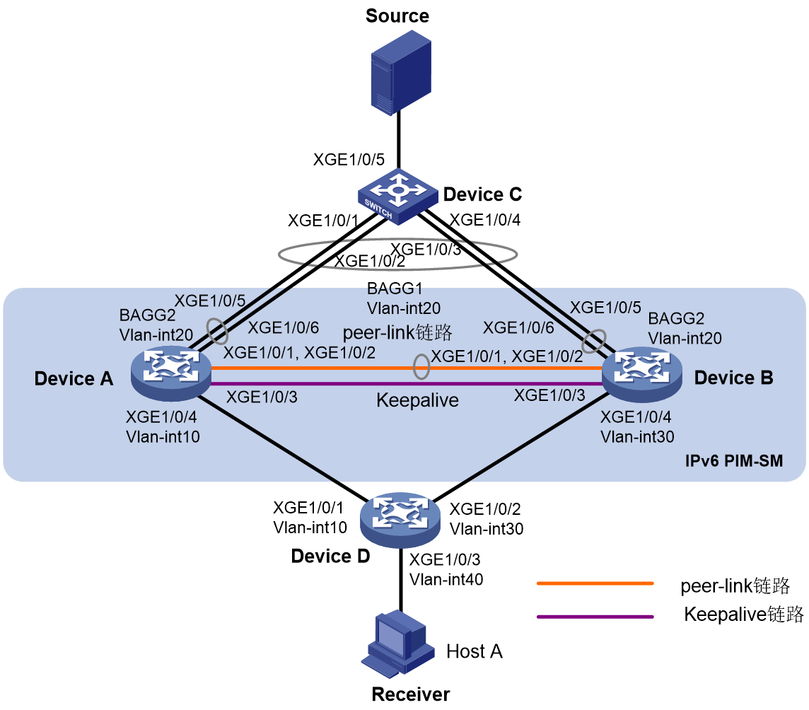
· 网络中运行OSPFv3协议,接收者通过组播方式接收视频点播信息,不同组织的接收者群体组成末梢网络,每个末梢网络中都存在至少一个接收者,整个IPv6 PIM域采用SM非管理域方式。
· DeviceC作为二层设备,通过接口Ten-GigabitEthernet1/0/5与组播源互联,通过聚合口1与Device A和Device B形成的M-LAG系统互联。组播源发送的组播数据流量,通过Device C的聚合口进行负载分担,发送到Device A和Device B的M-LAG接口上。Device A和Device B上的Vlan-interface20接口上配置的IP地址作为组播源接入M-LAG系统的网关地址。组播接收者Host A通过Device D接入M-LAG系统。
· 配置Device A和Device B的三层以太网接口Ten-GigabitEthernet1/0/3为保留接口,在该三层以太网接口上搭建Keepalive链路,保证Keepalive报文能够正常传输。
· 在Device A的Vlan-interface 20接口上配置VRRP,设置Device A在备份组1中的优先级为200,以保证Device A成为Master,从而与Device A在M-LAG中角色一致。
· Device A和Device B的分布式聚合接口上,允许VLAN 20通过,并在各自的Vlan-interface 20接口上配置IPv6 PIM协议。
· Device A和Device B上使能IPv6组播路由功能。
图2 三层组播支持M-LAG(组播源在M-LAG系统侧)组网图
|
设备 |
接口 |
IP地址 |
设备 |
接口 |
IP地址 |
|
Device A |
Vlan-int20 |
2000::1/80 |
Device D |
Vlan-int10 |
2003::2/80 |
|
|
XGE1/0/3 |
2002::1/80 |
|
Vlan-int30 |
2004::2/80 |
|
|
Vlan-int10 |
2003::1/80 |
|
Vlan-int40 |
20::1/80 |
|
|
Loop0 |
1111::1111/128 |
|
|
|
|
Device B |
Vlan-int20 |
2000::2/80 |
|
|
|
|
|
XGE1/0/3 |
2002::2/80 |
|
|
|
|
|
Vlan-int30 |
2004::1/80 |
|
|
|
|
|
Loop0 |
2222::2222/128 |
|
|
|
表2 适用产品及版本
|
产品 |
软件版本 |
|
S12500G-AF系列交换机 |
Release 7639P01及以上版本 |
|
S10500X系列交换机 |
Release 7639P01及以上版本 |
|
S12500-XS系列交换机 |
Release 7639P01及以上版本 |
|
S7600E-X系列交换机 |
Release 7639P01及以上版本 |
|
S7500X-X系列交换机 |
Release 7639P01及以上版本 |
|
S10500系列交换机 |
Release 7639P01及以上版本 |
|
S7600-X系列交换机 |
Release 7639P01及以上版本 |
|
S12500-S系列交换机 |
Release 7639P01及以上版本 |
|
S7500E-X系列交换机 |
Release 7639P01及以上版本 |
|
S7500E系列交换机 |
Release 7639P01及以上版本 |
|
S7500X系列交换机 |
Release 7639P01及以上版本 |
|
S7600系列交换机 |
Release 7639P01及以上版本 |
|
S7000ET系列交换机 |
Release 7639P01及以上版本 |
请按照上图配置各接口的IPv6地址和前缀,并在IPv6 PIM-SM域内的各交换机上配置OSPFv3协议,具体配置略。
# 配置M-LAG系统。
<DeviceA> system-view
[DeviceA] m-lag system-mac 1-1-1
[DeviceA] m-lag system-number 1
[DeviceA] m-lag system-priority 123
# 配置Keepalive报文的目的IPv6地址和源IPv6地址。
[DeviceA] m-lag keepalive ipv6 destination 2002::2 source 2002::1
# 配置Keepalive链路接口为保留接口。
[DeviceA] m-lag mad exclude interface ten-gigabitethernet 1/0/3
# 创建二层聚合接口1,并配置该接口为动态聚合模式。
[DeviceA] interface bridge-aggregation 1
[DeviceA-Bridge-Aggregation1] link-aggregation mode dynamic
[DeviceA-Bridge-Aggregation1] quit
# 将接口Ten-GigabitEthernet1/0/1和Ten-GigabitEthernet1/0/2加入到聚合组1中。
[DeviceA] interface ten-gigabitethernet 1/0/1
[DeviceA-Ten-GigabitEthernet1/0/1] port link-aggregation group 1
[DeviceA-Ten-GigabitEthernet1/0/1] quit
[DeviceA] interface ten-gigabitethernet 1/0/2
[DeviceA-Ten-GigabitEthernet1/0/2] port link-aggregation group 1
[DeviceA-Ten-GigabitEthernet1/0/2] quit
# 创建二层聚合接口2,并配置该接口为动态聚合模式。
[DeviceA] interface bridge-aggregation 2
[DeviceA-Bridge-Aggregation2] link-aggregation mode dynamic
[DeviceA-Bridge-Aggregation2] quit
# 将接口Ten-GigabitEthernet1/0/5和Ten-GigabitEthernet1/0/6加入到聚合组2中。
[DeviceA] interface ten-gigabitethernet 1/0/5
[DeviceA-Ten-GigabitEthernet1/0/5] port link-aggregation group 2
[DeviceA-Ten-GigabitEthernet1/0/5] quit
[DeviceA] interface ten-gigabitethernet 1/0/6
[DeviceA-Ten-GigabitEthernet1/0/6] port link-aggregation group 2
[DeviceA-Ten-GigabitEthernet1/0/6] quit
# 配置二层聚合接口1为Trunk端口,并允许所有VLAN的报文通过,并配置该接口为peer-link接口。
[DeviceA] interface bridge-aggregation 1
[DeviceA-Bridge-Aggregation1] port link-type trunk
[DeviceA-Bridge-Aggregation1] port trunk permit vlan all
[DeviceA-Bridge-Aggregation1] port m-lag intra-portal-port 1
[DeviceA-Bridge-Aggregation1] quit
# 配置二层聚合接口2为Trunk端口,并允许VLAN 20的报文通过,并配置该接口为M-LAG接口。
[DeviceA] interface bridge-aggregation 2
[DeviceA-Bridge-Aggregation2] port link-type trunk
[DeviceA-Bridge-Aggregation2] port trunk permit vlan 20
[DeviceA-Bridge-Aggregation2] port m-lag group 1
[DeviceA-Bridge-Aggregation2] quit
# 在Vlan-interface 20接口上配置VRRP,设置Device A在备份组1中的优先级为200,以保证Device A成为Master,从而与Device A在M-LAG中角色一致。
[DeviceA] interface vlan-interface 20
[DeviceA-Vlan-interface20] vrrp ipv6 vrid 1 virtual-ip FE80::10 link-local
[DeviceA-Vlan-interface20] vrrp ipv6 vrid 1 virtual-ip 2000::10
[DeviceA-Vlan-interface20] vrrp ipv6 vrid 1 priority 200
[DeviceA-Vlan-interface20] quit
# 开启IPv6组播路由,在Vlan-interface10接口上开启MLD和IPv6 PIM,并在其它接口上使能IPv6 PIM-SM。
[DeviceA] ipv6 multicast routing
[DeviceA-mrib6] quit
[DeviceA] interface vlan-interface 10
[DeviceA-Vlan-interface10] mld enable
[DeviceA-Vlan-interface10] ipv6 pim sm
[DeviceA-Vlan-interface10] quit
[DeviceA] interface vlan-interface 20
[DeviceA-Vlan-interface20] ipv6 pim sm
[DeviceA-Vlan-interface20] quit
[DeviceA] interface loopback 0
[DeviceA-LoopBack0] ipv6 pim sm
[DeviceA-LoopBack0] quit
# 配置本设备上LoopBack0接口地址为C-RP和C-BSR。
[DeviceA] ipv6 pim
[DeviceA-pim6] c-rp 1111::1111
[DeviceA-pim6] c-bsr 1111::1111
[DeviceA-pim6] quit
Device B的配置与Device A相似,配置过程略。
# 创建二层聚合接口1,并配置该接口为动态聚合模式。
<DeviceC> system-view
[DeviceC] interface bridge-aggregation 1
[DeviceC-Bridge-Aggregation1] link-aggregation mode dynamic
[DeviceC-Bridge-Aggregation1] quit
# 将端口Ten-GigabitEthernet1/0/1~Ten-GigabitEthernet1/0/4加入到聚合组1中。
[DeviceC] interface range ten-gigabitethernet 1/0/1 to ten-gigabitethernet 1/0/4
[DeviceC-if-range] port link-aggregation group 1
[DeviceC-if-range] quit
# 配置二层聚合接口1为Trunk端口,允许VLAN 20的报文通过。
[DeviceC] interface bridge-aggregation 1
[DeviceC-Bridge-Aggregation1] port link-type trunk
[DeviceC-Bridge-Aggregation1] port trunk permit vlan 20
[DeviceC-Bridge-Aggregation1] quit
# 将Ten-GigabitEthernet1/0/5加入VLAN 20。
[DeviceC] interface ten-gigabitethernet 1/0/5
[DeviceC-Ten-GigabitEthernet1/0/5] port access vlan 20
[DeviceC-Ten-GigabitEthernet1/0/5] quit
# 将Ten-GigabitEthernet1/0/1、Ten-GigabitEthernet1/0/2和Ten-GigabitEthernet1/0/3分别加入VLAN 10、30和40。
<DeviceD> system-view
[DeviceD] vlan 10
[DeviceD-vlan10] quit
[DeviceD] interface ten-gigabitethernet1/0/1
[DeviceD-Ten-GigabitEthernet1/0/1] port access vlan 10
[DeviceD-Ten-GigabitEthernet1/0/1] quit
[DeviceD] vlan 40
[DeviceD-vlan40] quit
[DeviceD] interface ten-gigabitethernet1/0/3
[DeviceD-Ten-GigabitEthernet1/0/3] port access vlan 40
[DeviceD] vlan 30
[DeviceD-vlan30] quit
[DeviceD] interface ten-gigabitethernet1/0/2
[DeviceD-Ten-GigabitEthernet1/0/2] port access vlan 30
# 使能IPv6组播路由,并在Vlan-interface10和Vlan-interface30接口上使能IPv6 PIM-SM。
[DeviceD] ipv6 multicast routing
[DeviceD-mrib6] quit
[DeviceD] interface vlan-interface 10
[DeviceD-Vlan-interface10] ipv6 pim sm
[DeviceD-Vlan-interface10] quit
[DeviceD] vlan 30
[DeviceD-vlan30] quit
[DeviceD] interface vlan-interface 30
[DeviceD-Vlan-interface30] ipv6 pim sm
[DeviceD-Vlan-interface30] quit
# 在Vlan-interface40接口上开启MLD功能,并将MLD版本配置为2。
[DeviceD] interface vlan-interface 40
[DeviceD-Vlan-interface40] mld enable
[DeviceD-Vlan-interface40] mld version 2
[DeviceD-Vlan-interface40] quit
# 在Device B上执行display m-lag keepalive命令,查看M-LAG系统中Keepalive报文的信息。
<DeviceB> display m-lag keepalive
Neighbor keepalive link status (cause): Up
Neighbor is alive for: 2128 s 421 ms
Keepalive packet transmission status:
Sent: Successful
Received: Successful
Last received keepalive packet information:
Source IP address: 2002::1
Time: 2021/12/21 15:45:15
Action: Accept
M-LAG keepalive parameters:
Destination IP address: 2002::1
Source IP address: 2002::2
Keepalive UDP port : 6400
Keepalive VPN name : N/A
Keepalive interval : 1000 ms
Keepalive timeout : 5 sec
Keepalive hold time: 3 sec
# 在Device B上执行display m-lag summary命令,查看M-LAG系统的接口摘要信息。
<DeviceB> display m-lag summary
Flags: A -- Aggregate interface down, B -- No peer M-LAG interface configured
C -- Configuration consistency check failed
Peer-link interface: BAGG1
Peer-link interface state (cause): UP
Keepalive link state (cause): UP
M-LAG interface information
M-LAG IF M-LAG group Local state (cause) Peer state Remaining down time(s)
BAGG2 1 UP UP -
# 在Device B上执行display link-aggregation verbose命令,查看聚合接口2所对应聚合组的详细信息。
<DeviceB> display link-aggregation verbose bridge-aggregation 2
Loadsharing Type: Shar -- Loadsharing, NonS -- Non-Loadsharing
Port Status: S -- Selected, U -- Unselected, I -- Individual
Port: A -- Auto port, M -- Management port, R -- Reference port
Flags: A -- LACP_Activity, B -- LACP_Timeout, C -- Aggregation,
D -- Synchronization, E -- Collecting, F -- Distributing,
G -- Defaulted, H -- Expired
Aggregate Interface: Bridge-Aggregation2
Creation Mode: Manual
Aggregation Mode: Dynamic
Loadsharing Type: Shar
Management VLANs: None
System ID: 0x7b, 0001-0001-0001
Local:
Port Status Priority Index Oper-Key Flag
XGE1/0/5(R) S 32768 32770 40001 {ACDEF}
XGE1/0/6 S 32768 32770 40001 {ACDEF}
Remote:
Actor Priority Index Oper-Key SystemID Flag
XGE1/0/5 32768 2 1 0x8000, 84c4-42e5-0300 {ACDEF}
XGE1/0/6 32768 2 1 0x8000, 84c4-42e5-0300 {ACDEF}
# 在Device D上执行display mld group命令,查看MLD组播组的信息。
<DeviceD> display mld group
MLD groups in total: 1
Vlan-interface40(FE80::200:FCFF:FE00:3472):
MLD groups reported in total: 1
Group address: FF08::2
Last reporter: FE80::1
Uptime: 01:56:46
Expires: 00:02:43
# 在Device B上执行display ipv6 pim routing-table命令查看IPv6 PIM路由表项。
<DeviceB> display ipv6 pim routing-table
Total 1 (*, G) entries; 1 (S, G) entries
(*, FF08::2)
RP: 2222::2222(local)
Protocol: pim-sm, Flag: WC
UpTime: 00:17:51
Upstream interface: Register-Tunnel0
Upstream neighbor: NULL
RPF prime neighbor: NULL
Downstream interface information:
Total number of downstream interfaces: 1
1: Vlan-interface30
Protocol: pim-sm, UpTime: 00:17:51, Expires: 00:02:39
(2000::111, FF08::2)
RP: 2222::2222(local)
Protocol: pim-sm, Flag: LOC
UpTime: 00:17:54
Upstream interface: Vlan-interface20
Upstream neighbor: NULL
RPF prime neighbor: NULL
Downstream interface information:
Total number of downstream interfaces: 1
1: Vlan-interface30
Protocol: pim-sm, UpTime: 00:17:54, Expires: 00:02:36
# 在Device B上执行display ipv6 multicast forwarding-table命令查看IPv6组播转发表项。
<DeviceB> display ipv6 multicast forwarding-table
Total 1 entries, 1 matched
00001. (2000::111, FF08::2)
Flags: 0x0
Uptime: 00:08:27, Timeout in: 00:03:27
Incoming interface: Vlan-interface20
List of 1 outgoing interfaces:
1: Vlan-interface30
Matched 23531 packets(194368 bytes), Wrong If 0 packets
Forwarded 23531 packets(171592 bytes)
在Device A上执行display ipv6 pim routing-table和display ipv6 multicast forwarding-table命令,查看不到对应的IPv6 PIM路由表项和IPv6组播转发表项,表明所有的组播流量此时均通过Device B发送给下游接收者。
· Device A
#
sysname DeviceA
#
ospfv3 1
router-id 2.2.2.2
area 0.0.0.0
#
vlan 10
#
vlan 20
#
interface Bridge-Aggregation1
port link-type trunk
port trunk permit vlan all
link-aggregation mode dynamic
port m-lag intra-portal-port 1
#
interface Bridge-Aggregation2
port link-type trunk
port trunk permit vlan 1 20
link-aggregation mode dynamic
port m-lag group 1
#
interface LoopBack0
ospfv3 1 area 0.0.0.0
ipv6 pim sm
ipv6 address 1111::1111/128
#
interface Vlan-interface10
ospfv3 1 area 0.0.0.0
ipv6 pim sm
ipv6 address 2003::1/80
#
interface Vlan-interface20
ospfv3 1 area 0.0.0.0
ipv6 pim sm
ipv6 address 2000::1/80
vrrp ipv6 vrid 1 virtual-ip FE80::10 link-local
vrrp ipv6 vrid 1 virtual-ip 2000::10
vrrp ipv6 vrid 1 priority 200
#
interface Ten-GigabitEthernet1/0/3
ipv6 address 2002::1/80
#
interface Ten-GigabitEthernet1/0/5
port link-type trunk
port trunk permit vlan 1 20
port link-aggregation group 2
#
interface Ten-GigabitEthernet1/0/6
port link-type trunk
port trunk permit vlan 1 20
port link-aggregation group 2
#
interface Ten-GigabitEthernet1/0/4
port access vlan 10
#
interface Ten-GigabitEthernet1/0/1
port link-type trunk
port trunk permit vlan 1 20
port link-aggregation group 1
#
interface Ten-GigabitEthernet1/0/2
port link-type trunk
port trunk permit vlan 1 20
port link-aggregation group 1
#
ipv6 multicast routing
#
ipv6 pim
c-bsr 1111::1111
c-rp 1111::1111
#
m-lag system-mac 0001-0001-0001
m-lag system-number 1
m-lag system-priority 123
m-lag keepalive ipv6 destination 2002::2 source 2002::1
m-lag mad exclude interface Ten-GigabitEthernet1/0/3
#
· Device B
#
sysname DeviceB
#
ospfv3 1
router-id 3.3.3.3
area 0.0.0.0
#
vlan 20
#
vlan 30
#
interface Bridge-Aggregation1
port link-type trunk
port trunk permit vlan all
link-aggregation mode dynamic
port m-lag intra-portal-port 1
#
interface Bridge-Aggregation2
port link-type trunk
port trunk permit vlan 1 20
link-aggregation mode dynamic
port m-lag group 1
#
interface LoopBack0
ospfv3 1 area 0.0.0.0
ipv6 pim sm
ipv6 address 2222::2222/128
#
interface Vlan-interface20
ospfv3 1 area 0.0.0.0
ipv6 pim sm
ipv6 address 2000::2/80
vrrp ipv6 vrid 1 virtual-ip FE80::10 link-local
vrrp ipv6 vrid 1 virtual-ip 2000::10
vrrp ipv6 vrid 1 priority 100
#
interface Vlan-interface30
ospfv3 1 area 0.0.0.0
ipv6 pim sm
ipv6 address 2004::1/80
#
interface Ten-GigabitEthernet1/0/3
ospfv3 1 area 0.0.0.0
ipv6 address 2002::2/80
#
interface Ten-GigabitEthernet1/0/5
port link-type trunk
port trunk permit vlan 1 20
port link-aggregation group 2
#
interface Ten-GigabitEthernet1/0/6
port link-type trunk
port trunk permit vlan 1 20
port link-aggregation group 2
#
interface Ten-GigabitEthernet1/0/4
port access vlan 30
#
interface Ten-GigabitEthernet1/0/1
port link-type trunk
port trunk permit vlan 1 20
port link-aggregation group 1
#
interface Ten-GigabitEthernet1/0/2
port link-type trunk
port trunk permit vlan 1 20
port link-aggregation group 1
#
ipv6 multicast routing
#
ipv6 pim
c-bsr 2222::2222
c-rp 2222::2222
#
m-lag system-mac 0001-0001-0001
m-lag system-number 2
m-lag system-priority 123
m-lag keepalive ipv6 destination 2002::1 source 2002::2
m-lag mad exclude interface Ten-GigabitEthernet1/0/3
#
· Device C
#
sysname DeviceC
#
vlan 20
#
interface Bridge-Aggregation1
port link-type trunk
port trunk permit vlan 1 20
link-aggregation mode dynamic
#
interface LoopBack1
ipv6 address FE80::2 link-local
#
interface Ten-GigabitEthernet1/0/5
port access vlan 20
#
interface Ten-GigabitEthernet1/0/1
port link-type trunk
port trunk permit vlan 1 20
port link-aggregation group 1
#
interface Ten-GigabitEthernet1/0/2
port link-type trunk
port trunk permit vlan 1 20
port link-aggregation group 1
#
interface Ten-GigabitEthernet1/0/3
port link-type trunk
port trunk permit vlan 1 20
port link-aggregation group 1
#
interface Ten-GigabitEthernet1/0/4
port link-type trunk
port trunk permit vlan 1 20
port link-aggregation group 1
#
· Device D
#
sysname DeviceD
#
ospfv3 1
router-id 4.4.4.4
area 0.0.0.0
#
vlan 10
#
vlan 40
#
vlan 30
#
interface Vlan-interface10
ospfv3 1 area 0.0.0.0
ipv6 pim sm
ipv6 address 2003::2/80
#
interface Vlan-interface40
ospfv3 1 area 0.0.0.0
ipv6 address 20::1/80
mld enable
mld version 2
#
interface Vlan-interface30
ospfv3 1 area 0.0.0.0
ipv6 pim sm
ipv6 address 2004::2/80
#
interface Ten-GigabitEthernet1/0/3
port access vlan 40
#
interface Ten-GigabitEthernet1/0/1
port access vlan 10
#
interface Ten-GigabitEthernet1/0/2
port access vlan 30
#
ipv6 multicast routing
#
pim
#
不同款型规格的资料略有差异, 详细信息请向具体销售和400咨询。H3C保留在没有任何通知或提示的情况下对资料内容进行修改的权利!