- Table of Contents
-
- 02-Configuration Examples
- 01-H3C_AAA_Configuration_Examples
- 02-H3C_ACL_Configuration_Examples
- 03-H3C_IGMP_Configuration_Examples
- 04-H3C_IP_Source_Guard_Configuration_Examples
- 05-H3C_Ethernet_OAM_Configuration_Examples
- 06-H3C_NQA_Configuration_Examples
- 07-H3C_QinQ_Configuration_Examples
- 08-H3C_OSPF_Configuration_Examples
- 09-H3C_MPLS_TE_Configuration_Examples
- 10-H3C_OpenFlow_Configuration_Examples
- 11-H3C_NAT_Configuration_Examples
- 12-H3C_RBAC_Configuration_Examples
- 13-H3C_DHCP_Relay_Redundancy_Configuration_Examples
- 14-H3C_DLDP_Configuration_Examples
- 15-H3C_IS-IS_Configuration_Examples
- 16-H3C_MPLS_L3VPN_Configuration_Examples
- 17-H3C_SSH_Configuration_Examples
- 18-H3C_Login_Management_Configuration_Examples
- 19-H3C_SNMP_Configuration_Examples
- 20-H3C_Priority_Marking_and_Queue_Scheduling_Configuration_Examples
- 21-H3C_Multicast_VPN_Configuration_Examples
- 22-H3C_BGP_Configuration_Examples
- 23-H3C_HoVPN_Configuration_Examples
- 24-H3C_L2TP_Configuration_Examples
- 25-H3C_VRRP_Configuration_Examples
- 26-H3C_Traffic_Filtering_Configuration_Examples
- 27-H3C_Samplers_and_IPv4_NetStream_Configuration_Examples
- 28-H3C_MPLS_L2VPN_Configuration_Examples
- 29-H3C_NetStream_Configuration_Examples
- 30-H3C_Policy-Based_Routing_Configuration_Examples
- 31-H3C_Traffic_Policing_Configuration_Examples
- 32-H3C_BFD_Configuration_Examples
- 33-H3C_OSPFv3_Configuration_Examples
- 34-H3C_VPLS_Configuration_Examples
- 35-H3C_GTS_and_Rate_Limiting_Configuration_Examples
- 36-H3C_IPv6_IS-IS_Configuration_Examples
- 37-H3C_MPLS OAM_Configuration_Examples
- 38-H3C_BGP_Route_Selection_Configuration_Examples
- 39-H3C_IS-IS_Route_Summarization_Configuration_Examples
- 40-H3C_SRv6 Configuration Examples
- 41-H3C_Attack_Protection_Configuration_Examples
- 42-H3C_OSPF_Multi-Process_Configuration_Examples
- 43-H3C_OSPF_with_Multi-Instance_Configuration_Examples
- 44-H3C_ARP_Attack_Protection_Configuration_Examples
- 45-H3C_DHCPv6_Server_and_DHCPv6_Prefix_Client_Configuration_Examples
- 46-General QoS Configuration Examples
- 47-GRE Tunnel Establishment Using OSPF Configuration Examples
- 48-GRE Tunnel Establishment Using Static Routes Configuration Examples
- 49-QoS Configuration Examples for the Financial Industry
- Related Documents
-
| Title | Size | Download |
|---|---|---|
| 48-GRE Tunnel Establishment Using Static Routes Configuration Examples | 96.35 KB |
Contents
Introduction
The following information provides an example of configuring GRE tunnels using static routes.
Prerequisites
This document is not restricted to specific software or hardware versions. Procedures and information in the examples might be slightly different depending on the software or hardware version of the device.
The configuration examples were created and verified in a lab environment, and all the devices were started with the factory default configuration. When you are working on a live network, make sure you understand the potential impact of every command on your network.
The following information is provided based on the assumption that you have basic knowledge of GRE and static routes.
Configuration examples
Network configuration
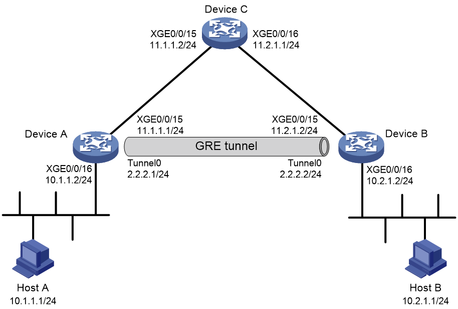
As shown in Figure 1, Device A, Device B, and Device C run OSPF. Establish a directly connected link between Device A and Device B so that Host A and Host B can communicate with each other. The specific requirements are as follows:
· Configure Device A as the default gateway for Host A, and Device B as the default gateway for Host B.
· Establish a directly connected link between Device A and Device B. Use static routes to specify forwarding of packets to the peer ends through the corresponding tunnel interfaces.
Analysis
To meet the network requirements, perform the following tasks:
· To establish a GRE tunnel between Device A and Device B, complete GRE-related configurations.
· To transmit packets between Host A and Host B through the GRE tunnel, configure a directly connected route to Host B on Device A and a directly connected route to Host A on Device B.
Procedures
Configuring Device A
1. Assign an IP address to each interface, as shown in Figure 1. (Details not shown.)
2. Configure basic OSPF functions.
<DeviceA> system-view
[DeviceA] ospf
[DeviceA-ospf-1] area 0
[DeviceA-ospf-1-area-0.0.0.0] network 11.1.1.0 0.0.0.255
[DeviceA-ospf-1-area-0.0.0.0] network 11.2.1.0 0.0.0.255
[DeviceA-ospf-1-area-0.0.0.0] quit
[DeviceA-ospf-1] quit
3. Configure a GRE tunnel:
# Create tunnel interface Tunnel 0, and specify the tunnel mode as GRE/IPv4.
[DeviceA] interface tunnel 0 mode gre
# Assign an IP address to interface Tunnel 0.
[DeviceA-Tunnel0] ip address 2.2.2.1 255.255.255.0
# Configure the source address of interface Tunnel 0 (as the IP address of Ten-GigabitEthernet0/0/15 on Device A).
[DeviceA-Tunnel0] source 11.1.1.1
# Configure the destination address of interface Tunnel 0 (as the IP address of Ten-GigabitEthernet0/0/15 on Device B).
[DeviceA-Tunnel0] destination 11.2.1.2
[DeviceA-Tunnel0] quit
4. Configure a static route to the subnet where Host B resides.
[DeviceA] ip route-static 10.2.1.0 255.255.255.0 Tunnel 0
Configuring Device B
1. Assign an IP address to each interface, as shown in Figure 1. (Details not shown.)
2. Configure basic OSPF functions.
<DeviceB> system-view
[DeviceB] ospf
[DeviceB-ospf-1] area 0
[DeviceB-ospf-1-area-0.0.0.0] network 11.2.1.0 0.0.0.255
[DeviceB-ospf-1-area-0.0.0.0] quit
[DeviceB-ospf-1] quit
3. Configure a GRE tunnel:
# Create tunnel interface Tunnel 0, and specify the tunnel mode as GRE/IPv4.
[DeviceB] interface tunnel 0 mode gre
# Assign an IP address to interface Tunnel 0.
[DeviceB-Tunnel0] ip address 2.2.2.2 255.255.255.0
# Configure the source address of interface Tunnel 0 (as the IP address of Ten-GigabitEthernet0/0/15 on Device B).
[DeviceB-Tunnel0] source 11.2.1.2
# Configure the destination address of interface Tunnel 0 (as the IP address of Ten-GigabitEthernet0/0/15 on Device A).
[DeviceB-Tunnel0] destination 11.1.1.1
[DeviceB-Tunnel0] quit
4. Configure a static route to the subnet where Host A resides.
[DeviceB] ip route-static 10.1.1.0 255.255.255.0 Tunnel 0
Configuring Device C
1. Assign an IP address to each interface, as shown in Figure 1. (Details not shown.)
2. Configure basic OSPF functions.
<DeviceC> system-view
[DeviceC] ospf
[DeviceC-ospf-1] area 0
[DeviceC-ospf-1-area-0.0.0.0] network 11.1.1.0 0.0.0.255
[DeviceC-ospf-1-area-0.0.0.0] network 11.2.1.0 0.0.0.255
[DeviceC-ospf-1-area-0.0.0.0] quit
[DeviceC-ospf-1] quit
Verifying the configuration
# Execute the display ip routing-table command on Device A. Verify that Device A has learned the OSPF route to the 11.2.1.0/24 subnet.
<DeviceA>display ip routing-table
Destinations : 15 Routes : 15
Destination/Mask Proto Pre Cost NextHop Interface
2.2.2.0/24 Direct 0 0 2.2.2.1 Tun0
2.2.2.1/32 Direct 0 0 127.0.0.1 InLoop0
2.2.2.255/32 Direct 0 0 2.2.2.1 Tun0
10.1.1.0/24 Direct 0 0 10.1.1.2 XGE0/0/16
10.1.1.2/32 Direct 0 0 127.0.0.1 InLoop0
10.1.1.255/32 Direct 0 0 10.1.1.2 XGE0/0/16
10.2.1.0/24 Static 60 0 0.0.0.0 Tun0
11.1.1.0/24 Direct 0 0 11.1.1.1 XGE0/0/15
11.1.1.1/32 Direct 0 0 127.0.0.1 InLoop0
11.1.1.255/32 Direct 0 0 11.1.1.1 XGE0/0/15
11.2.1.0/24 O_INTRA 10 2 11.1.1.2 XGE0/0/15
127.0.0.0/8 Direct 0 0 127.0.0.1 InLoop0
127.0.0.1/32 Direct 0 0 127.0.0.1 InLoop0
127.255.255.255/32 Direct 0 0 127.0.0.1 InLoop0
255.255.255.255/32 Direct 0 0 127.0.0.1 InLoop0
# Execute the display ip routing-table command on Device B. Verify that Device B has learned the OSPF route to the 11.1.1.0/24 subnet.
<DeviceB>display ip routing-table
Destinations : 15 Routes : 15
Destination/Mask Proto Pre Cost NextHop Interface
2.2.2.0/24 Direct 0 0 2.2.2.2 Tun0
2.2.2.2/32 Direct 0 0 127.0.0.1 InLoop0
2.2.2.255/32 Direct 0 0 2.2.2.2 Tun0
10.1.1.0/24 Static 60 0 0.0.0.0 Tun0
10.2.1.0/24 Direct 0 0 10.2.1.2 XGE0/0/16
10.2.1.2/32 Direct 0 0 127.0.0.1 InLoop0
10.2.1.255/32 Direct 0 0 10.2.1.2 XGE0/0/16
11.1.1.0/24 O_INTRA 10 2 11.2.1.1 XGE0/0/15
11.2.1.0/24 Direct 0 0 11.2.1.2 XGE0/0/15
11.2.1.2/32 Direct 0 0 127.0.0.1 InLoop0
11.2.1.255/32 Direct 0 0 11.2.1.2 XGE0/0/15
127.0.0.0/8 Direct 0 0 127.0.0.1 InLoop0
127.0.0.1/32 Direct 0 0 127.0.0.1 InLoop0
127.255.255.255/32 Direct 0 0 127.0.0.1 InLoop0
255.255.255.255/32 Direct 0 0 127.0.0.1 InLoop0
# Execute the display interface brief command on Device A. Verify that the status of interface Tunnel 0 on Device A is up.
<DeviceA>display interface brief
Brief information on interfaces in route mode:
Link: ADM - administratively down; Stby - standby
Protocol: (s) - spoofing
Interface Link Protocol Primary IP Description
XGE0/0/15 UP UP 11.1.1.1
XGE0/0/16 UP UP 10.1.1.2
InLoop0 UP UP(s) --
NULL0 UP UP(s) --
Tun0 UP UP 2.2.2.1
# Execute the display interface brief command on Device B. Verify that the status of interface Tunnel 0 on Device B is up.
<DeviceB>display interface brief
Brief information on interfaces in route mode:
Link: ADM - administratively down; Stby - standby
Protocol: (s) - spoofing
Interface Link Protocol Primary IP Description
XGE0/0/15 UP UP 11.2.1.2
XGE0/0/16 UP UP 10.2.1.2
InLoop0 UP UP(s) --
NULL0 UP UP(s) --
Tun0 UP UP 2.2.2.2
# Execute the display ip routing-table command on Device A. Verify that the static route from Device A to the subnet where Host B resides goes through interface Tunnel 0.
<DeviceA>display ip routing-table
Destinations : 15 Routes : 15
Destination/Mask Proto Pre Cost NextHop Interface
2.2.2.0/24 Direct 0 0 2.2.2.1 Tun0
2.2.2.1/32 Direct 0 0 127.0.0.1 InLoop0
2.2.2.255/32 Direct 0 0 2.2.2.1 Tun0
10.1.1.0/24 Direct 0 0 10.1.1.2 XGE0/0/16
10.1.1.2/32 Direct 0 0 127.0.0.1 InLoop0
10.1.1.255/32 Direct 0 0 10.1.1.2 XGE0/0/16
10.2.1.0/24 Static 60 0 0.0.0.0 Tun0
11.1.1.0/24 Direct 0 0 11.1.1.1 XGE0/0/15
11.1.1.1/32 Direct 0 0 127.0.0.1 InLoop0
11.1.1.255/32 Direct 0 0 11.1.1.1 XGE0/0/15
11.2.1.0/24 O_INTRA 10 2 11.1.1.2 XGE0/0/15
127.0.0.0/8 Direct 0 0 127.0.0.1 InLoop0
127.0.0.1/32 Direct 0 0 127.0.0.1 InLoop0
127.255.255.255/32 Direct 0 0 127.0.0.1 InLoop0
255.255.255.255/32 Direct 0 0 127.0.0.1 InLoop0
# Execute the display ip routing-table command on Device B. Verify that the static route from Device B to the subnet where Host A resides goes through interface Tunnel 0.
<DeviceB>display ip routing-table
Destinations : 15 Routes : 15
Destination/Mask Proto Pre Cost NextHop Interface
2.2.2.0/24 Direct 0 0 2.2.2.2 Tun0
2.2.2.2/32 Direct 0 0 127.0.0.1 InLoop0
2.2.2.255/32 Direct 0 0 2.2.2.2 Tun0
10.1.1.0/24 Static 60 0 0.0.0.0 Tun0
10.2.1.0/24 Direct 0 0 10.2.1.2 XGE0/0/16
10.2.1.2/32 Direct 0 0 127.0.0.1 InLoop0
10.2.1.255/32 Direct 0 0 10.2.1.2 XGE0/0/16
11.1.1.0/24 O_INTRA 10 2 11.2.1.1 XGE0/0/15
11.2.1.0/24 Direct 0 0 11.2.1.2 XGE0/0/15
11.2.1.2/32 Direct 0 0 127.0.0.1 InLoop0
11.2.1.255/32 Direct 0 0 11.2.1.2 XGE0/0/15
127.0.0.0/8 Direct 0 0 127.0.0.1 InLoop0
127.0.0.1/32 Direct 0 0 127.0.0.1 InLoop0
127.255.255.255/32 Direct 0 0 127.0.0.1 InLoop0
255.255.255.255/32 Direct 0 0 127.0.0.1 InLoop0
# Verify that the private IP of Device A can ping the private IP of Device B.
<DeviceA>ping -a 10.1.1.2 10.2.1.2
Ping 10.2.1.2 (10.2.1.2) from 10.1.1.2: 56 data bytes, press CTRL+C to break
56 bytes from 10.2.1.2: icmp_seq=0 ttl=255 time=26.000 ms
56 bytes from 10.2.1.2: icmp_seq=1 ttl=255 time=1.000 ms
56 bytes from 10.2.1.2: icmp_seq=2 ttl=255 time=1.000 ms
56 bytes from 10.2.1.2: icmp_seq=3 ttl=255 time=1.000 ms
56 bytes from 10.2.1.2: icmp_seq=4 ttl=255 time=2.000 ms
--- Ping statistics for 10.2.1.2 ---
5 packet(s) transmitted, 5 packet(s) received, 0.0% packet loss
round-trip min/avg/max/std-dev = 1.000/6.200/26.000/9.908 ms
# Verify that Host A can ping Host B.
<HostA>ping 10.2.1.1
Ping 10.2.1.1 (10.2.1.1): 56 data bytes, press CTRL+C to break
56 bytes from 10.2.1.1: icmp_seq=0 ttl=253 time=3.000 ms
56 bytes from 10.2.1.1: icmp_seq=1 ttl=253 time=1.000 ms
56 bytes from 10.2.1.1: icmp_seq=2 ttl=253 time=2.000 ms
56 bytes from 10.2.1.1: icmp_seq=3 ttl=253 time=2.000 ms
56 bytes from 10.2.1.1: icmp_seq=4 ttl=253 time=2.000 ms
--- Ping statistics for 10.2.1.1 ---
5 packet(s) transmitted, 5 packet(s) received, 0.0% packet loss
round-trip min/avg/max/std-dev = 1.000/2.000/3.000/0.632 ms
Configuration files
· Device A:
#
ospf 1
area 0.0.0.0
network 11.1.1.0 0.0.0.255
network 11.2.1.0 0.0.0.255
#
interface Ten-GigabitEthernet0/0/15
port link-mode route
ip address 11.1.1.1 255.255.255.0
#
interface Ten-GigabitEthernet0/0/16
port link-mode route
ip address 10.1.1.2 255.255.255.0
#
interface Tunnel0 mode gre
ip address 2.2.2.1 255.255.255.0
source 11.1.1.1
destination 11.2.1.2
#
ip route-static 10.2.1.0 24 Tunnel0
#
return
· Device B:
#
ospf 1
area 0.0.0.0
network 11.2.1.0 0.0.0.255
#
interface Ten-GigabitEthernet0/0/15
port link-mode route
ip address 11.2.1.2 255.255.255.0
#
interface Ten-GigabitEthernet0/0/16
port link-mode route
ip address 10.2.1.2 255.255.255.0
#
interface Tunnel0 mode gre
ip address 2.2.2.2 255.255.255.0
source 11.2.1.2
destination 11.1.1.1
#
ip route-static 10.1.1.0 24 Tunnel0
#
return
· Device C:
#
ospf 1
area 0.0.0.0
network 11.1.1.0 0.0.0.255
network 11.2.1.0 0.0.0.255
#
interface Ten-GigabitEthernet0/0/15
port link-mode route
ip address 11.1.1.2 255.255.255.0
#
interface Ten-GigabitEthernet0/0/16
port link-mode route
ip address 11.2.1.1 255.255.255.0
#
return
Related documentation
· Layer 3—IP Services Configuration Guide
· Layer 3—IP Routing Configuration Guide
· Layer 3—IP Services Command Reference
· Layer 3—IP Routing Command Reference
