- Table of Contents
-
- 02-Configuration Examples
- 01-H3C_AAA_Configuration_Examples
- 02-H3C_ACL_Configuration_Examples
- 03-H3C_IGMP_Configuration_Examples
- 04-H3C_IP_Source_Guard_Configuration_Examples
- 05-H3C_Ethernet_OAM_Configuration_Examples
- 06-H3C_NQA_Configuration_Examples
- 07-H3C_QinQ_Configuration_Examples
- 08-H3C_OSPF_Configuration_Examples
- 09-H3C_MPLS_TE_Configuration_Examples
- 10-H3C_OpenFlow_Configuration_Examples
- 11-H3C_NAT_Configuration_Examples
- 12-H3C_RBAC_Configuration_Examples
- 13-H3C_DHCP_Relay_Redundancy_Configuration_Examples
- 14-H3C_DLDP_Configuration_Examples
- 15-H3C_IS-IS_Configuration_Examples
- 16-H3C_MPLS_L3VPN_Configuration_Examples
- 17-H3C_SSH_Configuration_Examples
- 18-H3C_Login_Management_Configuration_Examples
- 19-H3C_SNMP_Configuration_Examples
- 20-H3C_Priority_Marking_and_Queue_Scheduling_Configuration_Examples
- 21-H3C_Multicast_VPN_Configuration_Examples
- 22-H3C_BGP_Configuration_Examples
- 23-H3C_HoVPN_Configuration_Examples
- 24-H3C_L2TP_Configuration_Examples
- 25-H3C_VRRP_Configuration_Examples
- 26-H3C_Traffic_Filtering_Configuration_Examples
- 27-H3C_Samplers_and_IPv4_NetStream_Configuration_Examples
- 28-H3C_MPLS_L2VPN_Configuration_Examples
- 29-H3C_NetStream_Configuration_Examples
- 30-H3C_Policy-Based_Routing_Configuration_Examples
- 31-H3C_Traffic_Policing_Configuration_Examples
- 32-H3C_BFD_Configuration_Examples
- 33-H3C_OSPFv3_Configuration_Examples
- 34-H3C_VPLS_Configuration_Examples
- 35-H3C_GTS_and_Rate_Limiting_Configuration_Examples
- 36-H3C_IPv6_IS-IS_Configuration_Examples
- 37-H3C_MPLS OAM_Configuration_Examples
- 38-H3C_BGP_Route_Selection_Configuration_Examples
- 39-H3C_IS-IS_Route_Summarization_Configuration_Examples
- 40-H3C_SRv6 Configuration Examples
- 41-H3C_Attack_Protection_Configuration_Examples
- 42-H3C_OSPF_Multi-Process_Configuration_Examples
- 43-H3C_OSPF_with_Multi-Instance_Configuration_Examples
- 44-H3C_ARP_Attack_Protection_Configuration_Examples
- 45-H3C_DHCPv6_Server_and_DHCPv6_Prefix_Client_Configuration_Examples
- 46-General QoS Configuration Examples
- 47-GRE Tunnel Establishment Using OSPF Configuration Examples
- 48-GRE Tunnel Establishment Using Static Routes Configuration Examples
- 49-QoS Configuration Examples for the Financial Industry
- Related Documents
-
| Title | Size | Download |
|---|---|---|
| 16-H3C_MPLS_L3VPN_Configuration_Examples | 210.31 KB |
Introduction
This document provides MPLS L3VPN configuration examples.
Prerequisites
The configuration examples in this document were created and verified in a lab environment, and all the devices were started with the factory default configuration. When you are working on a live network, make sure you understand the potential impact of every command on your network.
This document assumes that you have basic knowledge of MPLS L3VPN.
Example: Configuring MPLS L3VPN
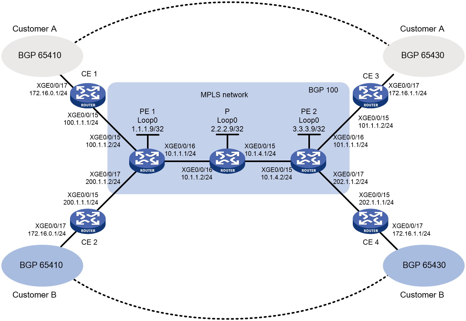
Network configuration
As shown in Figure 1, configure MPLS L3VPN to allow communication between different sites of a customer and to isolate different customers.
Analysis
To generate inner labels, and deliver VPN routing information to the remote PE, configure MP-BGP peers between PEs.
To generate outer labels to tunnel the VPN packets over the MPLS backbone, configure a routing protocol and MPLS LDP on the MPLS backbone.
To identify routing information for different customers on PEs, perform the following tasks on each PE:
· Create a VPN instance for each customer.
· Configure an RD and route targets for each VPN instance.
· Redistribute internal routes of each site to the corresponding VPN instance.
Restrictions and guidelines
Associating an interface with a VPN instance deletes the IP address of the interface. You must reconfigure the interface's IP address after the association.
Procedures
1. Configure OSPF on the MPLS backbone to ensure IP connectivity within the backbone:
# On PE 1, configure IP addresses for the loopback interface and the core-facing interface.
<PE1> system-view
[PE1] interface loopback 0
[PE1-LoopBack0] ip address 1.1.1.9 32
[PE1-LoopBack0] quit
[PE1] interface ten-gigabitethernet 0/0/16
[PE1-Ten-GigabitEthernet0/0/16] ip address 10.1.1.1 24
[PE1-Ten-GigabitEthernet0/0/16] quit
# On PE 1, configure OSPF to advertise backbone networks.
[PE1] ospf
[PE1-ospf-1] area 0
[PE1-ospf-1-area-0.0.0.0] network 10.1.1.0 0.0.0.255
[PE1-ospf-1-area-0.0.0.0] network 1.1.1.9 0.0.0.0
[PE1-ospf-1-area-0.0.0.0] quit
[PE1-ospf-1] quit
# On P, configure IP addresses for interfaces, including the loopback interface.
<P> system-view
[P] interface loopback 0
[P-LoopBack0] ip address 2.2.2.9 32
[P-LoopBack0] quit
[P] interface ten-gigabitethernet 0/0/16
[P-Ten-GigabitEthernet0/0/16] ip address 10.1.1.2 24
[P-Ten-GigabitEthernet0/0/16] quit
[P] interface ten-gigabitethernet 0/0/15
[P-Ten-GigabitEthernet0/0/15] ip address 10.1.4.1 24
[P-Ten-GigabitEthernet0/0/15] quit
# On P, configure OSPF to advertise backbone networks.
[P] ospf
[P-ospf-1] area 0
[P-ospf-1-area-0.0.0.0] network 10.1.1.0 0.0.0.255
[P-ospf-1-area-0.0.0.0] network 10.1.4.0 0.0.0.255
[P-ospf-1-area-0.0.0.0] network 2.2.2.9 0.0.0.0
[P-ospf-1-area-0.0.0.0] quit
[P-ospf-1] quit
# On PE 2, configure IP addresses for the loopback interface and the core-facing interface.
<PE2> system-view
[PE2] interface loopback 0
[PE2-LoopBack0] ip address 3.3.3.9 32
[PE2-LoopBack0] quit
[PE2] interface ten-gigabitethernet 0/0/15
[PE2-Ten-GigabitEthernet0/0/15] ip address 10.1.4.2 24
[PE2-Ten-GigabitEthernet0/0/15] quit
# On PE 2, configure OSPF to advertise backbone networks.
[PE2] ospf
[PE2-ospf-1] area 0
[PE2-ospf-1-area-0.0.0.0] network 10.1.4.0 0.0.0.255
[PE2-ospf-1-area-0.0.0.0] network 3.3.3.9 0.0.0.0
[PE2-ospf-1-area-0.0.0.0] quit
[PE2-ospf-1] quit
# Verify that OSPF neighbor relationships in Full state have been established on the backbone devices.
[PE1] display ospf peer verbose
OSPF Process 1 with Router ID 1.1.1.9
Neighbors
Area 0.0.0.0 interface 10.1.1.1(XGE0/0/16)'s neighbors
Router ID: 2.2.2.9 Address: 10.1.1.2 GR State: Normal
State: Full Mode: Nbr is Master Priority: 1
DR: 10.1.1.2 BDR: 10.1.1.1 MTU: 0
Options is 0x02 (-|-|-|-|-|-|E|-)
Dead timer due in 38 sec
Neighbor is up for 17:30:25
Authentication Sequence: [ 0 ]
Neighbor state change count: 6
BFD status: Disabled
# Verify that the PEs have learned the routes to the loopback interfaces of each other.
[PE1] display ip routing-table protocol ospf
Summary Count : 5
OSPF Routing table Status : <Active>
Summary Count : 3
Destination/Mask Proto Pre Cost NextHop Interface
2.2.2.9/32 O_INTRA 10 1 10.1.1.2 XGE0/0/16
3.3.3.9/32 O_INTRA 10 2 10.1.1.2 XGE0/0/16
10.1.4.0/24 O_INTRA 10 2 10.1.1.2 XGE0/0/16
OSPF Routing table Status : <Inactive>
Summary Count : 2
Destination/Mask Proto Pre Cost NextHop Interface
1.1.1.9/32 O_INTRA 10 0 1.1.1.9 Loop0
10.1.1.0/24 O_INTRA 10 1 10.1.1.1 XGE0/0/16
2. Configure basic MPLS and MPLS LDP on the MPLS backbone to establish LDP LSPs:
# Configure PE 1.
[PE1] mpls lsr-id 1.1.1.9
[PE1] mpls ldp
[PE1-ldp] quit
[PE1] interface ten-gigabitethernet 0/0/16
[PE1-Ten-GigabitEthernet0/0/16] mpls enable
[PE1-Ten-GigabitEthernet0/0/16] mpls ldp enable
[PE1-Ten-GigabitEthernet0/0/16] quit
# Configure P.
[P] mpls lsr-id 2.2.2.9
[P] mpls ldp
[P-ldp] quit
[P] interface ten-gigabitethernet 0/0/16
[P-Ten-GigabitEthernet0/0/16] mpls enable
[P-Ten-GigabitEthernet0/0/16] mpls ldp enable
[P-Ten-GigabitEthernet0/0/16] quit
[P] interface ten-gigabitethernet 0/0/15
[P-Ten-GigabitEthernet0/0/15] mpls enable
[P-Ten-GigabitEthernet0/0/15] mpls ldp enable
[P-Ten-GigabitEthernet0/0/15] quit
# Configure PE 2.
[PE2] mpls lsr-id 3.3.3.9
[PE2] mpls ldp
[PE2-ldp] quit
[PE2] interface ten-gigabitethernet 0/0/15
[PE2-Ten-GigabitEthernet0/0/15] mpls enable
[PE2-Ten-GigabitEthernet0/0/15] mpls ldp enable
[PE2-Ten-GigabitEthernet0/0/15] quit
# Verify that LDP sessions in Operational state have been established.
[PE1] display mpls ldp peer
Total number of peers: 1
Peer LDP ID State Role GR MD5 KA Sent/Rcvd
2.2.2.9:0 Operational Passive Off Off 5/5
# Verify that the LSPs have been established by LDP.
[PE1] display mpls ldp lsp
Status Flags: * - stale, L - liberal, B - backup
FECs: 4 Ingress: 1 Transit: 1 Egress: 3
FEC In/Out Label Nexthop OutInterface
1.1.1.9/32 3/-
-/1151(L)
2.2.2.9/32 -/3 10.1.1.2 XGE0/0/16
1151/3 10.1.1.2 XGE0/0/16
3.3.3.9/32 -/1150 10.1.1.2 XGE0/0/16
1150/1150 10.1.1.2 XGE0/0/16
3. Configure VPN instances on PEs to allow CE access:
# On PE 1, create VPN instance customerA for Customer A.
[PE1] ip vpn-instance customerA
# On PE 1, configure the RD as 100:1 for the VPN instance.
[PE1-vpn-instance-customerA] route-distinguisher 100:1
# On PE 1, specify the import target as 111:1 and the export target as 222:1 for the VPN instance. You can configure the same value for both the import and export targets to simplify management.
[PE1-vpn-instance-customerA] vpn-target 111:1 import-extcommunity
[PE1-vpn-instance-customerA] vpn-target 222:1 export-extcommunity
[PE1-vpn-instance-customerA] quit
# On PE 1, create VPN instance customerB for Customer B.
[PE1] ip vpn-instance customerB
# On PE 1, configure the RD as 200:1 for the VPN instance.
[PE1-vpn-instance-customerB] route-distinguisher 200:1
# On PE 1, specify the import target and export target for the VPN instance as 333:1 and 444:1.
[PE1-vpn-instance-customerB] vpn-target 333:1 import-extcommunity
[PE1-vpn-instance-customerB] vpn-target 444:1 export-extcommunity
[PE1-vpn-instance-customerB] quit
# On PE 1, associate Ten-GigabitEthernet0/0/15 with VPN instance customerA.
[PE1] interface ten-gigabitethernet 0/0/15
[PE1-Ten-GigabitEthernet0/0/15] ip binding vpn-instance customerA
[PE1-Ten-GigabitEthernet0/0/15] ip address 100.1.1.2 24
[PE1-Ten-GigabitEthernet0/0/15] quit
# On PE 1, associate Ten-GigabitEthernet0/0/17 with VPN instance customerB.
[PE1] interface Ten-GigabitEthernet0/0/17
[PE1-Ten-GigabitEthernet0/0/17] ip binding vpn-instance customerB
[PE1-Ten-GigabitEthernet0/0/17] ip address 200.1.1.2 24
[PE1-Ten-GigabitEthernet0/0/17] quit
# On PE 2, create VPN instance customerA for Customer A.
[PE2] ip vpn-instance customerA
# On PE 2, configure an RD for the VPN instance. H3C recommends configuring the same RD as the one configured for VPN instance customerA on PE 1.
[PE2-vpn-instance-customerA] route-distinguisher 100:1
# On PE 2, specify the import target and export target the same as the export target and import target on PE 1.
[PE2-vpn-instance-customerA] vpn-target 222:1 import-extcommunity
[PE2-vpn-instance-customerA] vpn-target 111:1 export-extcommunity
[PE2-vpn-instance-customerA] quit
# On PE 2, create VPN instance customerB for Customer B.
[PE2] ip vpn-instance customerB
# On PE 2, configure the RD as 200:1 for the VPN instance.
[PE2-vpn-instance-customerB] route-distinguisher 200:1
# On PE 2, specify the import target and export target the same as the export target and import target on PE 1.
[PE2-vpn-instance-customerB] vpn-target 444:1 import-extcommunity
[PE2-vpn-instance-customerB] vpn-target 333:1 export-extcommunity
[PE2-vpn-instance-customerB] quit
# On PE 2, associate Ten-GigabitEthernet0/0/16 with VPN instance customerA.
[PE2] interface ten-gigabitethernet 0/0/16
[PE2-Ten-GigabitEthernet0/0/16] ip binding vpn-instance customerA
[PE2-Ten-GigabitEthernet0/0/16] ip address 101.1.1.1 24
[PE2-Ten-GigabitEthernet0/0/16] quit
# On PE 2, associate Ten-GigabitEthernet0/0/17 with VPN instance customerB.
[PE2] interface Ten-GigabitEthernet0/0/17
[PE2-Ten-GigabitEthernet0/0/17] ip binding vpn-instance customerB
[PE2-Ten-GigabitEthernet0/0/17] ip address 202.1.1.2 24
[PE2-Ten-GigabitEthernet0/0/17] quit
# Configure IP addresses for interfaces on the CEs, as shown in Figure 1. (Details not shown.)
# Execute the display ip vpn-instance command on the PEs to display VPN instance configurations.
[PE1] display ip vpn-instance
<Sysname> display ip vpn-instance
Total VPN-Instances configured : 2
Total IPv4 VPN-Instances configured : 0
Total IPv6 VPN-Instances configured : 0
Total IPv4 VPN-Instances EVPN configured : 0
Total IPv6 VPN-Instances EVPN configured : 0
VPN-Instance Name RD Address family Create time
customerA 100:1 N/A 2022/9/02 10:59:57
customerA 200:1 N/A 2022/9/02 11:00:20
# Use the ping command on the PEs to verify that the PEs can ping their attached CEs.
[PE1] ping -vpn-instance customerA 100.1.1.1
Ping 10.1.1.1 (100.1.1.1): 56 data bytes, press CTRL_C to break
56 bytes from 100.1.1.1: icmp_seq=0 ttl=255 time=1.000 ms
56 bytes from 100.1.1.1: icmp_seq=1 ttl=255 time=2.000 ms
56 bytes from 100.1.1.1: icmp_seq=2 ttl=255 time=0.000 ms
56 bytes from 100.1.1.1: icmp_seq=3 ttl=255 time=1.000 ms
56 bytes from 100.1.1.1: icmp_seq=4 ttl=255 time=0.000 ms
--- Ping statistics for 10.1.1.1 ---
5 packet(s) transmitted, 5 packet(s) received, 0.0% packet loss
round-trip min/avg/max/std-dev = 0.000/0.800/2.000/0.748 ms
4. Establish EBGP peer relationships between PEs and CEs, and redistribute VPN routes into BGP:
# On PE 1, create BGP process 100.
[PE1] bgp 100
# On PE 1, specify CE 1 as a peer and redistribute direct routes of CE 1 into the BGP routing table of VPN instance customerA.
[PE1-bgp-default] ip vpn-instance customerA
[PE1-bgp-default-customerA] peer 100.1.1.1 as-number 65410
[PE1-bgp-default-customerA] address-family ipv4 unicast
[PE1-bgp-default-ipv4-customerA] peer 100.1.1.1 enable
[PE1-bgp-default-ipv4-customerA] import-route direct
[PE1-bgp-default-ipv4-customerA] quit
[PE1-bgp-default-customerA] quit
# On PE 1, specify CE 2 as a peer and redistribute direct routes of CE 2 into the BGP routing table of VPN instance customerB.
[PE1-bgp-default] ip vpn-instance customerB
[PE1-bgp-default-customerB] peer 200.1.1.1 as-number 65410
[PE1-bgp-default-customerB] address-family ipv4 unicast
[PE1-bgp-default-ipv4-customerB] peer 200.1.1.1 enable
[PE1-bgp-default-ipv4-customerB] import-route direct
[PE1-bgp-default-ipv4-customerB] quit
[PE1-bgp-default-customerB] quit
[PE1-bgp-default] quit
# On PE 2, create BGP process 100.
[PE2] bgp 100
# On PE 2, specify CE 3 as a peer and redistribute direct routes of CE 3 into the BGP routing table of VPN instance customerA.
[PE2-bgp-default] ip vpn-instance customerA
[PE2-bgp-default-customerA] peer 101.1.1.2 as-number 65430
[PE2-bgp-default-customerA] address-family ipv4 unicast
[PE2-bgp-default-ipv4-customerA] peer 101.1.1.2 enable
[PE2-bgp-default-ipv4-customerA] import-route direct
[PE2-bgp-default-ipv4-customerA] quit
[PE2-bgp-default-customerA] quit
# On PE 2, specify CE 4 as a peer and redistribute direct routes of CE 4 into the BGP routing table of VPN instance customerB.
[PE2-bgp-default] ip vpn-instance customerB
[PE2-bgp-default-customerB] peer 202.1.1.1 as-number 65430
[PE2-bgp-default-customerB] address-family ipv4 unicast
[PE2-bgp-default-ipv4-customerB] peer 202.1.1.1 enable
[PE2-bgp-default-ipv4-customerB] import-route direct
[PE2-bgp-default-ipv4-customerB] quit
[PE2-bgp-default-customerB] quit
[PE2-bgp-default] quit
# On CE 1, create BGP process 65410, specify 100.1.1.2 as the peer, and specify the peer's AS number as 100.
<CE1> system-view
[CE1] bgp 65410
[CE1-bgp-default] peer 100.1.1.2 as-number 100
# On CE 1, enable BGP to exchange IPv4 unicast routing information with peer 100.1.1.2.
[CE1-bgp-default] address-family ipv4 unicast
[CE1-bgp-default-ipv4] peer 100.1.1.2 enable
# On CE 1, redistribute the direct route for the site into EBGP.
[CE1-bgp-default-ipv4] import-route direct
[CE1-bgp-default-ipv4] quit
[CE1-bgp-default] quit
# On CE 2, create BGP process 65410, specify 200.1.1.2 as the peer, and specify the peer's AS number as 100.
<CE2> system-view
[CE2] bgp 65410
[CE2-bgp-default] peer 200.1.1.2 as-number 100
# On CE 2, enable BGP to exchange IPv4 unicast routing information with peer 200.1.1.2.
[CE2-bgp-default] address-family ipv4 unicast
[CE2-bgp-default-ipv4] peer 200.1.1.2 enable
# On CE 2, redistribute the direct route for the site into EBGP.
[CE2-bgp-default-ipv4] import-route direct
[CE2-bgp-default-ipv4] quit
[CE2-bgp-default] quit
# On CE 3, create BGP process 65430, specify 101.1.1.1 as the peer, and specify the peer's AS number as 100.
<CE3> system-view
[CE3] bgp 65430
[CE3-bgp-default] peer 101.1.1.1 as-number 100
# On CE 3, enable BGP to exchange IPv4 unicast routing information with peer 101.1.1.1.
[CE3-bgp-default] address-family ipv4 unicast
[CE3-bgp-default-ipv4] peer 101.1.1.1 enable
# On CE 3, redistribute the direct route for the site into EBGP.
[CE3-bgp-default-ipv4] import-route direct
[CE3-bgp-default-ipv4] quit
[CE3-bgp-default] quit
# On CE 4, create BGP process 65430, specify 202.1.1.2 as the peer, and specify the peer's AS number as 100.
<CE4> system-view
[CE4] bgp 65430
[CE4-bgp-default] peer 202.1.1.2 as-number 100
# On CE 4, enable BGP to exchange IPv4 unicast routing information with peer 202.1.1.2.
[CE4-bgp-default] address-family ipv4 unicast
[CE4-bgp-default-ipv4] peer 202.1.1.2 enable
# On CE 4, redistribute the direct route for the site into EBGP.
[CE4-bgp-default-ipv4] import-route direct
[CE4-bgp-default-ipv4] quit
[CE4-bgp-default] quit
# Verify that a BGP peer relationship in Established state has been established between a PE and a CE.
[PE1] display bgp peer ipv4 vpn-instance customerA
BGP local router ID: 1.1.1.9
Local AS number: 100
Total number of peers: 1 Peers in established state: 1
* - Dynamically created peer
Peer AS MsgRcvd MsgSent OutQ PrefRcv Up/Down State
100.1.1.1 65410 4 4 0 2 13:35:25 Established
5. Create an MP-IBGP peer relationship between PEs:
# On PE 1, configure 3.3.3.9 as the BGP peer and specify Loopback 0 as the source interface for sending routing updates to the peer.
[PE1] bgp 100
[PE1-bgp-default] peer 3.3.3.9 as-number 100
[PE1-bgp-default] peer 3.3.3.9 connect-interface loopback 0
# On PE 1, enable the peer 3.3.3.9 for the BGP-VPNv4 address family.
[PE1-bgp] address-family vpnv4
[PE1-bgp-default-vpnv4] peer 3.3.3.9 enable
[PE1-bgp-default-vpnv4] quit
[PE1-bgp] quit
# On PE 2, configure 1.1.1.9 as the BGP peer and specify Loopback 0 as the source interface for sending routing updates to the peer.
[PE2] bgp 100
[PE2-bgp-default] peer 1.1.1.9 as-number 100
[PE2-bgp-default] peer 1.1.1.9 connect-interface loopback 0
# On PE 2, enable the peer 1.1.1.9 for the BGP-VPNv4 address family.
[PE2-bgp] address-family vpnv4
[PE2-bgp-default-vpnv4] peer 1.1.1.9 enable
[PE2-bgp-default-vpnv4] quit
[PE2-bgp-default] quit
# Verify that a BGP peer relationship in Established state has been established between the PEs.
[PE1] display bgp peer vpnv4
BGP local router ID: 1.1.1.9
Local AS number: 100
Total number of peers: 1 Peers in established state: 1
Peer AS MsgRcvd MsgSent OutQ PrefRcv Up/Down State
3.3.3.9 100 8 8 0 0 00:00:08 Established
Verifying the configuration
# Execute the display ip routing-table vpn-instance command on the PEs.
[PE1] display ip routing-table vpn-instance customerA
Destinations : 13 Routes : 13
Destination/Mask Proto Pre Cost NextHop Interface
0.0.0.0/32 Direct 0 0 127.0.0.1 InLoop0
100.1.1.0/24 Direct 0 0 100.1.1.2 XGE0/0/15
100.1.1.0/32 Direct 0 0 100.1.1.2 XGE0/0/15
100.1.1.2/32 Direct 0 0 127.0.0.1 InLoop0
100.1.1.255/32 Direct 0 0 100.1.1.2 XGE0/0/15
101.1.1.0/24 BGP 255 0 3.3.3.9 XGE0/0/16
127.0.0.0/8 Direct 0 0 127.0.0.1 InLoop0
127.0.0.0/32 Direct 0 0 127.0.0.1 InLoop0
127.0.0.1/32 Direct 0 0 127.0.0.1 InLoop0
127.255.255.255/32 Direct 0 0 127.0.0.1 InLoop0
224.0.0.0/4 Direct 0 0 0.0.0.0 NULL0
224.0.0.0/24 Direct 0 0 0.0.0.0 NULL0
255.255.255.255/32 Direct 0 0 127.0.0.1 InLoop0
The output shows that PE 1 has a route to the remote CE of Customer A. Output on PE 2 is similar.
# Verify that CEs of the same VPN can ping each other, whereas those of different VPNs cannot. For example, CE 1 can ping CE 3 (101.1.1.2), but it cannot ping CE 4 (202.1.1.1). (Details not shown.)
Configuration files
· PE 1:
#
ip vpn-instance customerA
route-distinguisher 100:1
vpn-target 111:1 import-extcommunity
vpn-target 222:1 export-extcommunity
#
ip vpn-instance customerB
route-distinguisher 200:1
vpn-target 333:1 import-extcommunity
vpn-target 444:1 export-extcommunity
#
ospf 1
area 0.0.0.0
network 1.1.1.9 0.0.0.0
network 10.1.1.0 0.0.0.255
#
mpls lsr-id 1.1.1.9
#
mpls ldp
#
interface LoopBack0
ip address 1.1.1.9 255.255.255.255
#
interface Ten-GigabitEthernet0/0/15
port link-mode route
ip binding vpn-instance customerA
ip address 100.1.1.2 255.255.255.0
#
interface Ten-GigabitEthernet0/0/16
port link-mode route
ip address 10.1.1.1 255.255.255.0
mpls enable
mpls ldp enable
#
interface Ten-GigabitEthernet0/0/17
port link-mode route
ip binding vpn-instance customerB
ip address 200.1.1.2 255.255.255.0
#
bgp 100
peer 3.3.3.9 as-number 100
peer 3.3.3.9 connect-interface LoopBack0
#
address-family vpnv4
peer 3.3.3.9 enable
#
ip vpn-instance customerA
peer 100.1.1.1 as-number 65410
#
address-family ipv4 unicast
import-route direct
peer 100.1.1.1 enable
#
ip vpn-instance customerB
peer 200.1.1.1 as-number 65410
#
address-family ipv4 unicast
import-route direct
peer 200.1.1.1 enable
#
· P:
#
ospf 1
area 0.0.0.0
network 2.2.2.9 0.0.0.0
network 10.1.1.0 0.0.0.255
network 10.1.4.0 0.0.0.255
#
mpls lsr-id 2.2.2.9
#
mpls ldp
#
interface LoopBack0
ip address 2.2.2.9 255.255.255.255
#
interface Ten-GigabitEthernet0/0/15
port link-mode route
ip address 10.1.4.1 255.255.255.0
mpls enable
mpls ldp enable
#
interface Ten-GigabitEthernet0/0/16
port link-mode route
ip address 10.1.1.2 255.255.255.0
mpls enable
mpls ldp enable
#
· PE 2:
#
ip vpn-instance customerA
route-distinguisher 100:1
vpn-target 111:1 export-extcommunity
vpn-target 222:1 import-extcommunity
#
ip vpn-instance customerB
route-distinguisher 200:1
vpn-target 333:1 export-extcommunity
vpn-target 444:1 import-extcommunity
#
ospf 1
area 0.0.0.0
network 10.1.4.0 0.0.0.255
network 3.3.3.9 0.0.0.0
#
mpls lsr-id 3.3.3.9
#
mpls ldp
#
interface LoopBack0
ip address 3.3.3.9 255.255.255.255
#
interface Ten-GigabitEthernet0/0/15
port link-mode route
ip address 10.1.4.2 255.255.255.0
mpls enable
mpls ldp enable
#
interface Ten-GigabitEthernet0/0/16
port link-mode route
ip binding vpn-instance customerA
ip address 101.1.1.1 255.255.255.0
#
interface Ten-GigabitEthernet0/0/17
port link-mode route
ip binding vpn-instance customerB
ip address 202.1.1.2 255.255.255.0
#
bgp 100
peer 1.1.1.9 as-number 100
peer 1.1.1.9 connect-interface LoopBack0
#
address-family vpnv4
peer 1.1.1.9 enable
#
ip vpn-instance customerA
peer 101.1.1.2 as-number 65430
#
address-family ipv4 unicast
import-route direct
peer 101.1.1.2 enable
#
ip vpn-instance customerB
peer 202.1.1.1 as-number 65430
#
address-family ipv4 unicast
import-route direct
peer 202.1.1.1 enable
#
· CE 1:
#
interface Ten-GigabitEthernet0/0/15
port link-mode route
ip address 100.1.1.1 255.255.255.0
#
bgp 65410
peer 100.1.1.2 as-number 100
#
address-family ipv4 unicast
import-route direct
peer 100.1.1.2 enable
#
· CE 2:
#
interface Ten-GigabitEthernet0/0/15
port link-mode route
ip address 200.1.1.1 255.255.255.0
#
bgp 65410
peer 200.1.1.2 as-number 100
#
address-family ipv4 unicast
import-route direct
peer 200.1.1.2 enable
#
· CE 3:
#
interface Ten-GigabitEthernet0/0/15
port link-mode route
ip address 101.1.1.2 255.255.255.0
#
bgp 65430
peer 101.1.1.1 as-number 100
#
address-family ipv4 unicast
import-route direct
peer 101.1.1.1 enable
#
· CE 4:
#
interface Ten-GigabitEthernet0/0/15
port link-mode route
ip address 202.1.1.1 255.255.255.0
#
bgp 65430
peer 202.1.1.2 as-number 100
#
address-family ipv4 unicast
import-route direct
peer 202.1.1.2 enable
#
Related documentation
· H3C CR16000-M1A Routers MPLS Configuration Guide
· H3C CR16000-M1A Routers MPLS Command Reference
