- Table of Contents
-
- 02-Configuration Examples
- 01-H3C_AAA_Configuration_Examples
- 02-H3C_ACL_Configuration_Examples
- 03-H3C_IGMP_Configuration_Examples
- 04-H3C_IP_Source_Guard_Configuration_Examples
- 05-H3C_Ethernet_OAM_Configuration_Examples
- 06-H3C_NQA_Configuration_Examples
- 07-H3C_QinQ_Configuration_Examples
- 08-H3C_OSPF_Configuration_Examples
- 09-H3C_MPLS_TE_Configuration_Examples
- 10-H3C_OpenFlow_Configuration_Examples
- 11-H3C_NAT_Configuration_Examples
- 12-H3C_RBAC_Configuration_Examples
- 13-H3C_DHCP_Relay_Redundancy_Configuration_Examples
- 14-H3C_DLDP_Configuration_Examples
- 15-H3C_IS-IS_Configuration_Examples
- 16-H3C_MPLS_L3VPN_Configuration_Examples
- 17-H3C_SSH_Configuration_Examples
- 18-H3C_Login_Management_Configuration_Examples
- 19-H3C_SNMP_Configuration_Examples
- 20-H3C_Priority_Marking_and_Queue_Scheduling_Configuration_Examples
- 21-H3C_Multicast_VPN_Configuration_Examples
- 22-H3C_BGP_Configuration_Examples
- 23-H3C_HoVPN_Configuration_Examples
- 24-H3C_L2TP_Configuration_Examples
- 25-H3C_VRRP_Configuration_Examples
- 26-H3C_Traffic_Filtering_Configuration_Examples
- 27-H3C_Samplers_and_IPv4_NetStream_Configuration_Examples
- 28-H3C_MPLS_L2VPN_Configuration_Examples
- 29-H3C_NetStream_Configuration_Examples
- 30-H3C_Policy-Based_Routing_Configuration_Examples
- 31-H3C_Traffic_Policing_Configuration_Examples
- 32-H3C_BFD_Configuration_Examples
- 33-H3C_OSPFv3_Configuration_Examples
- 34-H3C_VPLS_Configuration_Examples
- 35-H3C_GTS_and_Rate_Limiting_Configuration_Examples
- 36-H3C_IPv6_IS-IS_Configuration_Examples
- 37-H3C_MPLS OAM_Configuration_Examples
- 38-H3C_BGP_Route_Selection_Configuration_Examples
- 39-H3C_IS-IS_Route_Summarization_Configuration_Examples
- 40-H3C_SRv6 Configuration Examples
- 41-H3C_Attack_Protection_Configuration_Examples
- 42-H3C_OSPF_Multi-Process_Configuration_Examples
- 43-H3C_OSPF_with_Multi-Instance_Configuration_Examples
- 44-H3C_ARP_Attack_Protection_Configuration_Examples
- 45-H3C_DHCPv6_Server_and_DHCPv6_Prefix_Client_Configuration_Examples
- 46-General QoS Configuration Examples
- 47-GRE Tunnel Establishment Using OSPF Configuration Examples
- 48-GRE Tunnel Establishment Using Static Routes Configuration Examples
- 49-QoS Configuration Examples for the Financial Industry
- Related Documents
-
| Title | Size | Download |
|---|---|---|
| 10-H3C_OpenFlow_Configuration_Examples | 99.25 KB |
Introduction
This document provides examples for configuring OpenFlow.
OpenFlow separates the control plane and the data forwarding plane. An OpenFlow device matches packets against one or more flow tables. A flow table contains one or more flow entries deployed by the controller. Packets are matched based on the matching precedence of flow entries.
Prerequisites
The configuration examples in this document were created and verified in a lab environment, and all the devices were started with the factory default configuration. When you are working on a live network, make sure you understand the potential impact of every command on your network.
This document assumes that you have basic knowledge of OpenFlow.
General restrictions and guidelines
For information about cards that support OpenFlow, see OpenFlow Configuration Guide.
When you configure OpenFlow, follow these restrictions and guidelines:
· Enable LLDP globally on OpenFlow devices so that the controller can learn the OpenFlow topology through LLDP.
· Configure each OpenFlow device with an interface for communicating with the controller so that OpenFlow instances can establish connections with the controller.
· To ensure high availability, use TCP or SSL to establish connections between OpenFlow devices and the controller. This example uses TCP. SSL provides higher availability than TCP.
· For the access ports of devices to belong to an OpenFlow instance, configure the Loosen mode when you associate VLANs 4092 and 4093 with the OpenFlow instance.
Example: Configuring OpenFlow to deploy dynamic flow entries
Network configuration
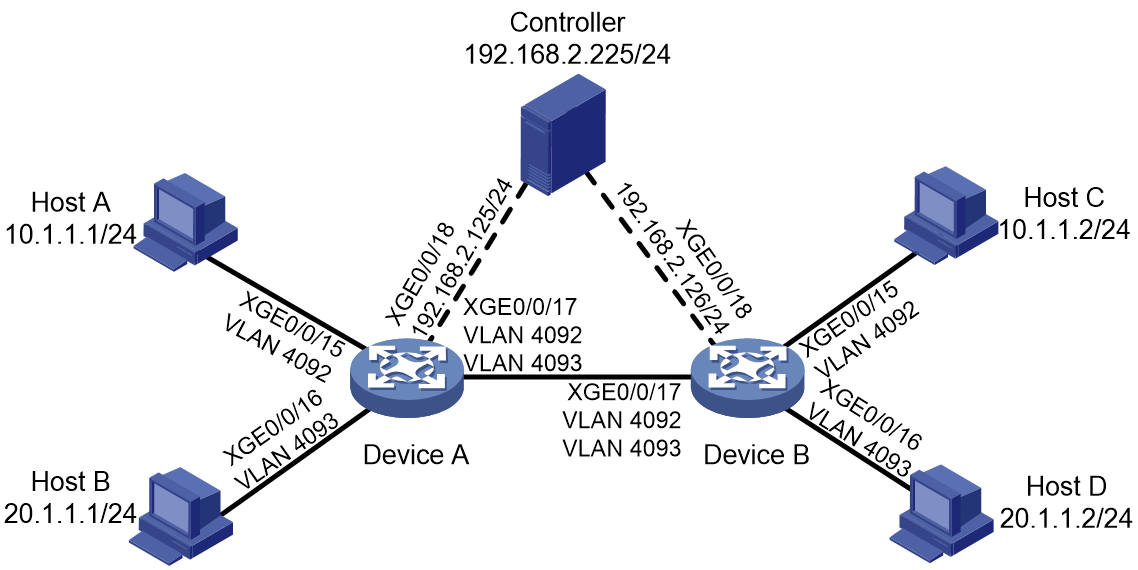
As shown in Figure 1, configure OpenFlow to meet the following requirements:
· The controller can deploy dynamic flow entries.
· Host A and Host C can communicate with each other based on the flow entries deployed by the controller.
· Host B and Host D can communicate with each other based on the flow entries deployed by the controller.
Procedures
Configuring Device A
# Create VLAN 4092 and VLAN 4093.
<DeviceA> system-view
[DeviceA] vlan 4092
[DeviceA-vlan4092] quit
[DeviceA] vlan 4093
[DeviceA-vlan4093] quit
# Configure Ten-GigabitEthernet 0/0/15, Ten-GigabitEthernet 0/0/16, and Ten-GigabitEthernet 0/0/17.
[DeviceA] interface Ten-GigabitEthernet 0/0/15
[DeviceA-Ten-GigabitEthernet0/0/15] port link-mode bridge
[DeviceA-Ten-GigabitEthernet0/0/15] port access vlan 4092
[DeviceA-Ten-GigabitEthernet0/0/15] quit
[DeviceA] interface Ten-GigabitEthernet 0/0/16
[DeviceA-Ten-GigabitEthernet0/0/16] port link-mode bridge
[DeviceA-Ten-GigabitEthernet0/0/16] port access vlan 4093
[DeviceA-Ten-GigabitEthernet0/0/16] quit
[DeviceA] interface Ten-GigabitEthernet 0/0/17
[DeviceA-Ten-GigabitEthernet0/0/17] port link-mode bridge
[DeviceA-Ten-GigabitEthernet0/0/17] port link-type trunk
[DeviceA-Ten-GigabitEthernet0/0/17] port trunk permit vlan 4092 4093
[DeviceA-Ten-GigabitEthernet0/0/17] quit
# Enable LLDP globally.
[DeviceA] lldp global enable
# Configure Ten-GigabitEthernet 0/0/18 on Switch A for communicating with the controller.
[DeviceA] interface Ten-GigabitEthernet 0/0/18
[DeviceA-Ten-GigabitEthernet0/0/18] ip address 192.168.2.125 255.255.255.0
[DeviceA-Ten-GigabitEthernet0/0/18] quit
# Create OpenFlow instance 1. Associate VLAN 4092 and VLAN 4093 with it in loosen mode.
[DeviceA] openflow instance 1
[DeviceA-of-inst-1] classification vlan 4092 mask 4092 loosen
# Configure the default action of table-miss flow entries to forward packets to the normal pipeline
[DeviceA-of-inst-1] default table-miss permit
# Specify controller 0 with IP address 192.168.2.225 for OpenFlow instance 1 and activate the instance..
[DeviceA-of-inst-1] controller 0 address ip 192.168.2.225
[DeviceA-of-inst-1] active instance
[DeviceA-of-inst-1] quit
Configuring Device B
# Create VLAN 4092 and VLAN 4093.
<DeviceB> system-view
[DeviceB] vlan 4092
[DeviceB-vlan4092] quit
[DeviceB] vlan 4093
[DeviceB-vlan4093] quit
# Configure Ten-GigabitEthernet 0/0/15, Ten-GigabitEthernet 0/0/16, and Ten-GigabitEthernet 0/0/17.
[DeviceB] interface Ten-GigabitEthernet 0/0/15
[DeviceB-Ten-GigabitEthernet0/0/15] port link-mode bridge
[DeviceB-Ten-GigabitEthernet0/0/15] port access vlan 4092
[DeviceB-Ten-GigabitEthernet0/0/15] quit
[DeviceB] interface Ten-GigabitEthernet 0/0/16
[DeviceB-Ten-GigabitEthernet0/0/16] port link-mode bridge
[DeviceB-Ten-GigabitEthernet0/0/16] port access vlan 4093
[DeviceB-Ten-GigabitEthernet0/0/16] quit
[DeviceB] interface Ten-GigabitEthernet 0/0/17
[DeviceB-Ten-GigabitEthernet0/0/17] port link-mode bridge
[DeviceB-Ten-GigabitEthernet0/0/17] port link-type trunk
[DeviceB-Ten-GigabitEthernet0/0/17] port trunk permit vlan 4092 4093
[DeviceB-Ten-GigabitEthernet0/0/17] quit
# Enable LLDP globally.
[DeviceB] lldp global enable
# Configure Ten-GigabitEthernet 0/0/18 on Switch B for communicating with the controller.
[DeviceB] interface Ten-GigabitEthernet 0/0/18
[DeviceB-Ten-GigabitEthernet0/0/18] ip address 192.168.2.126 255.255.255.0
[DeviceB-Ten-GigabitEthernet0/0/18] quit
# Create OpenFlow instance 1. Associate VLAN 4092 and VLAN 4093 with it in loosen mode.
[DeviceB] openflow instance 1
[DeviceB-of-inst-1] classification vlan 4092 mask 4092 loosen
# Configure the default action of table-miss flow entries to forward packets to the normal pipeline
[DeviceB-of-inst-1] default table-miss permit
# Specify the IP address for controller 0 as 192.168.2.225 for OpenFlow instance 1 and activate the instance.
[DeviceB-of-inst-1] controller 0 address ip 192.168.2.225
[DeviceB-of-inst-1] active instance
[DeviceB-of-inst-1] quit
Verifying the configuration
# Display details for OpenFlow instance 1 on devices, for example, Device A.
[DeviceA] display openflow instance 1
Instance 1 information:
Configuration information:
Description : --
Active status : Active
Inactive configuration:
None
Active configuration:
Classification: VLAN, loosen mode, total VLANs(2)
4092-4094
In-band management VLAN, total VLANs(0)
Empty VLAN
Connect mode: Multiple
MAC address learning: Enabled
TCP DSCP value: 10
Flow table:
Table ID(type): 0(Extensibility), count: 0
Flow-entry max-limit: 64000
Datapath ID: 0x0001123456789000
Default table-miss: Permit
Forbidden port: None
Qinq Network: Disabled
TCP connection backup: Enabled
User-plane: Disabled
Port information:
Ten-GigabitEthernet0/0/15
Ten-GigabitEthernet0/0/16
Ten-GigabitEthernet0/0/17
Active channel information:
Controller 0 IP address: 192.168.2.225 port: 6633
The output shows that Ten-GigabitEthernet 0/0/15, Ten-GigabitEthernet 0/0/16, and Ten-GigabitEthernet 0/0/17 belong to OpenFlow instance 1 and can be used to forward packets in the OpenFlow forwarding process.
# Display controller information for OpenFlow instance 1 on devices, for example, Device A.
[DeviceA] display openflow instance 1 controller
Instance 1 controller information:
Reconnect interval: 60 (s)
Echo interval : 5 (s)
Controller ID : 0
Controller IP address : 192.168.2.225
Controller port : 6633
Controller role : Equal
Connect type : TCP
Connect state : Established
Packets sent : 132
Packets received : 434
...
The output shows that Device A has established a connection with the controller.
# Ping Host C from Host A.
Ping 10.1.1.2 (10.1.1.2): 56 data bytes, press CTRL_C to break
56 bytes from 10.1.1.2: icmp_seq=0 ttl=255 time=4.582 ms
56 bytes from 10.1.1.2: icmp_seq=1 ttl=255 time=1.299 ms
56 bytes from 10.1.1.2: icmp_seq=2 ttl=255 time=1.389 ms
56 bytes from 10.1.1.2: icmp_seq=3 ttl=255 time=6.688 ms
56 bytes from 10.1.1.2: icmp_seq=4 ttl=255 time=1.294 ms
--- Ping statistics for 10.1.1.2 ---
5 packet(s) transmitted, 5 packet(s) received, 0.0% packet loss
round-trip min/avg/max/std-dev = 1.294/3.050/6.688/2.213 ms
The output shows that Host A and Host C can reach each other.
# Display flow table information for OpenFlow instance 1 again on devices, for example, Device A.
[DeviceA] display openflow instance 1 flow-table
Instance 1 flow table information:
Flow entry 1 information:
cookie: 0x2328, priority: 29999, hard time: 0, idle time: 300, flags:
flow_send_rem, byte count: --, packet count: 1
Match information:
Input interface: XGE0/0/17
Ethernet source MAC address: 7425-8a0f-8034
Ethernet source MAC address mask: ffff-ffff-ffff
Ethernet type: 0x0806
Instruction information:
Write actions:
Output interface: XGE0/0/15
Flow entry 2 information:
cookie: 0x2328, priority: 29999, hard time: 0, idle time: 300, flags:
flow_send_rem, byte count: --, packet count: 4
Match information:
Input interface: XGE0/0/15
Ethernet source MAC address: 0cda-41b1-d1c5
Ethernet source MAC address mask: ffff-ffff-ffff
Ethernet type: 0x0800
Instruction information:
Write actions:
Output interface: XGE0/0/17
Flow entry 3 information:
cookie: 0x2328, priority: 29999, hard time: 0, idle time: 300, flags:
flow_send_rem, byte count: --, packet count: 4
Match information:
Input interface: XGE0/0/17
Ethernet source MAC address: 7425-8a0f-8034
Ethernet source MAC address mask: ffff-ffff-ffff
Ethernet type: 0x0800
Instruction information:
Write actions:
Output interface: XGE0/0/15
The output shows the following information:
· The ARP request/reply packets and ICMP request/replay packets between Host A and Host C successfully trigger the controller to deploy flow entries.
· Switch A forwards packets based on the flow entries that are deployed by the controller.
# Ping Host D from Host B.
Ping 20.1.1.2 (20.1.1.2): 56 data bytes, press CTRL_C to break
56 bytes from 20.1.1.2: icmp_seq=0 ttl=255 time=1.620 ms
56 bytes from 20.1.1.2: icmp_seq=1 ttl=255 time=6.625 ms
56 bytes from 20.1.1.2: icmp_seq=2 ttl=255 time=1.454 ms
56 bytes from 20.1.1.2: icmp_seq=3 ttl=255 time=1.134 ms
56 bytes from 20.1.1.2: icmp_seq=4 ttl=255 time=1.260 ms
--- Ping statistics for 20.1.1.2 ---
5 packet(s) transmitted, 5 packet(s) received, 0.0% packet loss
round-trip min/avg/max/std-dev = 1.134/2.419/6.625/2.110 ms
The output shows that Host B and Host D can reach each other.
# Display flow table information for OpenFlow instance 1 again on devices, for example, Device A.
[DeviceA] display openflow instance 1 flow-table
Instance 1 flow table information:
Flow entry 1 information:
cookie: 0x2328, priority: 29999, hard time: 0, idle time: 300, flags:
flow_send_rem, byte count: --, packet count: 1
Match information:
Input interface: XGE0/0/17
Ethernet source MAC address: 7425-8a0f-8034
Ethernet source MAC address mask: ffff-ffff-ffff
Ethernet type: 0x0806
Instruction information:
Write actions:
Output interface: XGE0/0/15
Flow entry 2 information:
cookie: 0x2328, priority: 29999, hard time: 0, idle time: 300, flags:
flow_send_rem, byte count: --, packet count: 4
Match information:
Input interface: XGE0/0/15
Ethernet source MAC address: 0cda-41b1-d1c5
Ethernet source MAC address mask: ffff-ffff-ffff
Ethernet type: 0x0800
Instruction information:
Write actions:
Output interface: XGE0/0/17
Flow entry 3 information:
cookie: 0x2328, priority: 29999, hard time: 0, idle time: 300, flags:
flow_send_rem, byte count: --, packet count: 4
Match information:
Input interface: XGE0/0/17
Ethernet source MAC address: 7425-8a0f-8034
Ethernet source MAC address mask: ffff-ffff-ffff
Ethernet type: 0x0800
Instruction information:
Write actions:
Output interface: XGE0/0/15
Flow entry 4 information:
cookie: 0x2328, priority: 29999, hard time: 0, idle time: 300, flags:
flow_send_rem, byte count: --, packet count: 1
Match information:
Input interface: XGE0/0/17
Ethernet source MAC address: 7425-8a0f-8035
Ethernet source MAC address mask: ffff-ffff-ffff
Ethernet type: 0x0806
Instruction information:
Write actions:
Output interface: XGE0/0/16
Flow entry 5 information:
cookie: 0x2328, priority: 29999, hard time: 0, idle time: 300, flags:
flow_send_rem, byte count: --, packet count: 4
Match information:
Input interface: XGE0/0/16
Ethernet source MAC address: 0cda-41b1-d1c4
Ethernet source MAC address mask: ffff-ffff-ffff
Ethernet type: 0x0800
Instruction information:
Write actions:
Output interface: XGE0/0/17
Flow entry 6 information:
cookie: 0x2328, priority: 29999, hard time: 0, idle time: 300, flags:
flow_send_rem, byte count: --, packet count: 4
Match information:
Input interface: XGE0/0/17
Ethernet source MAC address: 7425-8a0f-8035
Ethernet source MAC address mask: ffff-ffff-ffff
Ethernet type: 0x0800
Instruction information:
Write actions:
Output interface: XGE0/0/16
The output shows the following information:
· The ARP request/reply packets and ICMP request/replay packets between Host B and Host D successfully trigger the controller to deploy flow entries.
· Switch A forwards packets based on the flow entries that are deployed by the controller.
Configuration files
· Device A:
#
lldp global enable
#
openflow instance 1
default table-miss permit
classification vlan 4092 mask 4092 loosen
controller 0 address ip 192.168.2.225
active instance
#
interface Ten-GigabitEthernet0/0/18
port link-mode route
ip address 192.168.2.125 255.255.255.0
#
interface Ten-GigabitEthernet0/0/15
port link-mode bridge
port access vlan 4092
#
interface Ten-GigabitEthernet0/0/16
port link-mode bridge
port access vlan 4093
#
interface Ten-GigabitEthernet0/0/17
port link-mode bridge
port link-type trunk
port trunk permit vlan 1 4092 to 4093
#
· Switch B:
#
lldp global enable
#
openflow instance 1
default table-miss permit
classification vlan 4092 mask 4092 loosen
controller 0 address ip 192.168.2.225
active instance
#
interface Ten-GigabitEthernet0/0/18
port link-mode route
ip address 192.168.2.126 255.255.255.0
#
interface Ten-GigabitEthernet0/0/15
port link-mode bridge
port access vlan 4092
#
interface Ten-GigabitEthernet0/0/16
port link-mode bridge
port access vlan 4093
#
interface Ten-GigabitEthernet0/0/17
port link-mode bridge
port link-type trunk
port trunk permit vlan 1 4092 to 4093
#
Related documentation
· H3C CR16000-M1A Routers OpenFlow Configuration Guide
· H3C CR16000-M1A Routers OpenFlow Command Reference
