- Table of Contents
-
- 02-Configuration Examples
- 01-H3C_AAA_Configuration_Examples
- 02-H3C_ACL_Configuration_Examples
- 03-H3C_ATM_Configuration_Examples
- 04-H3C_IGMP_Configuration_Examples
- 05-H3C_IP_Source_Guard_Configuration_Examples
- 06-H3C_Ethernet_OAM_Configuration_Examples
- 07-H3C_NQA_Configuration_Examples
- 08-H3C_QinQ_Configuration_Examples
- 09-H3C_OSPF_Configuration_Examples
- 10-H3C_MPLS_TE_Configuration_Examples
- 11-H3C_OpenFlow_Configuration_Examples
- 12-H3C_NAT_Configuration_Examples
- 13-H3C_RBAC_Configuration_Examples
- 14-H3C_IRF_Configuration_Examples
- 15-H3C_POS_Interface_Configuration_Examples
- 16-H3C_CPOS_Interface_Configuration_Examples
- 17-H3C_DHCP_Relay_Redundancy_Configuration_Examples
- 18-H3C_DLDP_Configuration_Examples
- 19-H3C_IS-IS_Configuration_Examples
- 20-H3C_MPLS_L3VPN_Configuration_Examples
- 21-H3C_SSH_Configuration_Examples
- 22-H3C_Login_Management_Configuration_Examples
- 23-H3C_SNMP_Configuration_Examples
- 24-H3C_Priority_Marking_and_Queue_Scheduling_Configuration_Examples
- 25-H3C_Multicast_VPN_Configuration_Examples
- 26-H3C_BGP_Configuration_Examples
- 27-H3C_HoVPN_Configuration_Examples
- 28-H3C_L2TP_Configuration_Examples
- 29-H3C_VRRP_Configuration_Examples
- 30-H3C_Traffic_Filtering_Configuration_Examples
- 31-H3C_Samplers_and_IPv4_NetStream_Configuration_Examples
- 32-H3C_Software_Upgrade_Examples
- 33-H3C_MPLS_L2VPN_Configuration_Examples
- 34-H3C_NetStream_Configuration_Examples
- 35-H3C_Policy-Based_Routing_Configuration_Examples
- 36-H3C_Traffic_Policing_Configuration_Examples
- 37-H3C_BFD_Configuration_Examples
- 38-H3C_OSPFv3_Configuration_Examples
- 39-H3C_VPLS_Configuration_Examples
- 40-H3C_GTS_and_Rate_Limiting_Configuration_Examples
- 41-H3C_IPv6_IS-IS_Configuration_Examples
- 42-H3C_MPLS OAM_Configuration_Examples
- 43-H3C_BGP_Route_Selection_Configuration_Examples
- 44-H3C_IS-IS_Route_Summarization_Configuration_Examples
- 45-H3C_SRv6 Configuration Examples
- 46-H3C_Attack_Protection_Configuration_Examples
- 47-H3C_OSPF_Multi-Process_Configuration_Examples
- 48-H3C_OSPF_with_Multi-Instance_Configuration_Examples
- 49-H3C_ARP_Attack_Protection_Configuration_Examples
- 50-H3C_DHCPv6_Server_and_DHCPv6_Prefix_Client_Configuration_Examples
- 51-CE1 Interface Connection Configuration Examples
- 52-GRE Tunnel Establishment Using OSPF Configuration Examples
- 53-GRE Tunnel Establishment Using Static Routes Configuration Examples
- 54-OSPF over IPsec for Overseas Branch Access Configuration Examples
- 55-General QoS Configuration Examples
- 56-QoS Configuration Examples for the Financial Industry
- Related Documents
-
| Title | Size | Download |
|---|---|---|
| 44-H3C_IS-IS_Route_Summarization_Configuration_Examples | 85.08 KB |
Example: Configuring IS-IS route summarization
Configuring IP addresses for interfaces
Configuring IS-IS route summarization
Introduction
This document provides IS-IS route summarization configuration examples.
Prerequisites
The configuration examples in this document were created and verified in a lab environment, and all the devices were started with the factory default configuration. When you are working on a live network, make sure you understand the potential impact of every command on your network.
This document assumes that you have basic knowledge of IS-IS route summarization.
Example: Configuring IS-IS route summarization
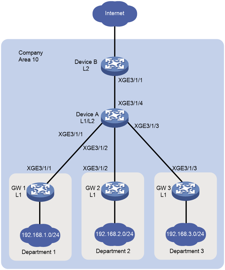
Network configuration
As shown in Figure 1, the five departments of a company use IS-IS to connect to the backbone network. The three departments are assigned the networks 192.168.1.0/24, 192.168.2.0/24, 192.168.3.0/24. Configure IS-IS route summarization to reduce routing entries and save system resources for Device B.
|
Device |
Interface |
IP Address |
Device |
Interface |
IP Address |
|
Device A |
XGE3/1/4 |
172.16.1.1/24 |
Device B |
XGE3/1/1 |
172.16.1.2/24 |
|
XGE3/1/1 |
10.1.1.1/24 |
GW 1 |
XGE3/1/1 |
10.1.1.2/24 |
|
|
XGE3/1/2 |
10.1.2.1/24 |
GW 2 |
XGE3/1/2 |
10.1.2.2/24 |
|
|
XGE3/1/3 |
10.1.3.1/24 |
GW3 |
XGE3/1/3 |
10.1.3.2/24 |
Analysis
Configure route summarization on Device A because route summarization applies only to locally generated LSPs.
To avoid blackhole routes, set the summary route to 192.168.0.0/22.
Procedures
Configuring IP addresses for interfaces
# Configure an IP address for interface Ten-GigabitEthernet 3/1/4 on Device A.
<DeviceA> system-view
[DeviceA] interface ten-gigabitethernet 3/1/4
[DeviceA-Ten-GigabitEthernet3/1/4] ip address 172.16.1.1 24
[DeviceA-Ten-GigabitEthernet3/1/4] quit
# Configure IP addresses for other interfaces as shown in Figure 1 in the same way VLAN-interface 10 is configured. (Details not shown.)
Configuring basic IS-IS
Configuring Device A
# Enable IS-IS on Device A and configure Device A as a Level-1-2 router.
[DeviceA] isis 1
[DeviceA-isis-1] network-entity 10.0000.0000.0001.00
[DeviceA-isis-1] is-level level-1-2
[DeviceA-isis-1] quit
# Enable IS-IS on interface Ten-GigabitEthernet 3/1/4.
[DeviceA] interface ten-gigabitethernet 3/1/4
[DeviceA–Ten-GigabitEthernet3/1/4] isis enable 1
[DeviceA–Ten-GigabitEthernet3/1/4] quit
# Configure other interfaces in the same way VLAN-interface 10 is configured. (Details not shown.)
Configuring Device B
# Enable IS-IS on Device B and configure Device B as a Level-2 router.
[DeviceB] isis 1
[DeviceB-isis-1] network-entity 10.0000.0000.0002.00
[DeviceB-isis-1] is-level level-2
[DeviceB-isis-1] quit
# Enable IS-IS on interface Ten-GigabitEthernet 3/1/1.
[DeviceB] interface ten-gigabitethernet 3/1/1
[DeviceB–Ten-GigabitEthernet3/1/1] isis enable 1
[DeviceB–Ten-GigabitEthernet3/1/1] quit
Configuring the gateways
# Enable IS-IS on GW 1 and configure GW 1 as a Level-1 router.
[GW1] isis 1
[GW1-isis-1] network-entity 10.0001.0001.0001.00
[GW1-isis-1] is-level level-1
[GW1-isis-1] quit
# Enable IS-IS on interface Ten-GigabitEthernet 3/1/1.
[GW1] interface ten-gigabitethernet 3/1/1
[GW1–Ten-GigabitEthernet3/1/1] isis enable 1
[GW1–Ten-GigabitEthernet3/1/1] quit
# Configure other gateways in the same way GW 1 is configured. (Details not shown.)
Displaying IS-IS routing information on Device B
# Display IS-IS routing information on Device B to view the network address of each department.
[DeviceB] display isis route
Route information for IS-IS(1)
-----------------------------
Level-2 IPv4 Forwarding Table
-----------------------------
IPv4 Destination IntCost ExtCost ExitInterface NextHop Flags
-------------------------------------------------------------------------------
192.168.1.0/24 30 NULL XGE3/1/1 172.16.1.1 R/-/-
10.1.1.0/24 20 NULL XGE3/1/1 172.16.1.1 R/-/-
192.168.2.0/24 30 NULL XGE3/1/1 172.16.1.1 R/-/-
10.1.2.0/24 20 NULL XGE3/1/1 172.16.1.1 R/-/-
192.168.3.0/24 30 NULL XGE3/1/1 172.16.1.1 R/-/-
10.1.3.0/24 20 NULL XGE3/1/1 172.16.1.1 R/-/-
172.16.1.0/24 10 NULL XGE3/1/1 Direct D/L/-
Flags: D-Direct, R-Added to Rib, L-Advertised in LSPs, U-Up/Down Bit Set
Configuring IS-IS route summarization
# Configure IS-IS route summarization on Device A.
[DeviceA] isis 1
[DeviceA-isis-1]address-family ipv4
[DeviceA-isis-1-ipv4] summary 192.168.0.0 22
Verifying the configuration
# Display IS-IS routing information on Device B.
[DeviceB] display isis route
Route information for IS-IS(1)
------------------------------
Level-2 IPv4 Forwarding Table
-----------------------------
IPv4 Destination IntCost ExtCost ExitInterface NextHop Flags
-------------------------------------------------------------------------------
10.1.1.0/24 20 NULL XGE3/1/1 172.16.1.1 R/-/-
10.1.2.0/24 20 NULL XGE3/1/1 172.16.1.1 R/-/-
10.1.3.0/24 20 NULL XGE3/1/1 172.16.1.1 R/-/-
172.16.1.0/24 10 NULL XGE3/1/1 Direct D/L/-
192.168.0.0/22 30 NULL XGE3/1/1 172.16.1.1 R/-/-
Flags: D-Direct, R-Added to Rib, L-Advertised in LSPs, U-Up/Down bit set
The output shows that the networks have been summarized into a single network 192.168.0.0/22.
Configuration files
Device A
#
isis 1
network-entity 10.0000.0000.0001.00
#
address-family ipv4 unicast
summary 192.168.0.0 255.255.252.0
#
interface ten-gigabitethernet 3/1/4
port link-mode route
ip address 172.16.1.1 255.255.255.0
isis enable 1
#
interface ten-gigabitethernet 3/1/1
port link-mode route
ip address 10.1.1.1 255.255.255.0
isis enable 1
#
interface ten-gigabitethernet 3/1/2
port link-mode route
ip address 10.1.2.1 255.255.255.0
isis enable 1
#
interface ten-gigabitethernet 3/1/3
port link-mode route
ip address 10.1.3.1 255.255.255.0
isis enable 1
#
Device B
#
isis 1
is-level level-2
network-entity 10.0000.0000.0002.00
#
interface ten-gigabitethernet 3/1/1
port link-mode route
ip address 172.16.1.2 255.255.255.0
isis enable 1
#
GW 1
#
isis 1
is-level level-1
network-entity 10.0001.0001.0001.00
#
interface ten-gigabitethernet 3/1/1
port link-mode route
ip address 10.1.1.2 255.255.255.0
isis enable 1
#
interface ten-gigabitethernet 3/1/2
port link-mode route
ip address 192.168.1.1 255.255.255.0
isis enable 1
#
The configuration files for other gateways are similar to the configuration file for GW 1. (Details not shown.)
