- Table of Contents
-
- 02-Configuration Examples
- 01-H3C_AAA_Configuration_Examples
- 02-H3C_ACL_Configuration_Examples
- 03-H3C_ATM_Configuration_Examples
- 04-H3C_IGMP_Configuration_Examples
- 05-H3C_IP_Source_Guard_Configuration_Examples
- 06-H3C_Ethernet_OAM_Configuration_Examples
- 07-H3C_NQA_Configuration_Examples
- 08-H3C_QinQ_Configuration_Examples
- 09-H3C_OSPF_Configuration_Examples
- 10-H3C_MPLS_TE_Configuration_Examples
- 11-H3C_OpenFlow_Configuration_Examples
- 12-H3C_NAT_Configuration_Examples
- 13-H3C_RBAC_Configuration_Examples
- 14-H3C_IRF_Configuration_Examples
- 15-H3C_POS_Interface_Configuration_Examples
- 16-H3C_CPOS_Interface_Configuration_Examples
- 17-H3C_DHCP_Relay_Redundancy_Configuration_Examples
- 18-H3C_DLDP_Configuration_Examples
- 19-H3C_IS-IS_Configuration_Examples
- 20-H3C_MPLS_L3VPN_Configuration_Examples
- 21-H3C_SSH_Configuration_Examples
- 22-H3C_Login_Management_Configuration_Examples
- 23-H3C_SNMP_Configuration_Examples
- 24-H3C_Priority_Marking_and_Queue_Scheduling_Configuration_Examples
- 25-H3C_Multicast_VPN_Configuration_Examples
- 26-H3C_BGP_Configuration_Examples
- 27-H3C_HoVPN_Configuration_Examples
- 28-H3C_L2TP_Configuration_Examples
- 29-H3C_VRRP_Configuration_Examples
- 30-H3C_Traffic_Filtering_Configuration_Examples
- 31-H3C_Samplers_and_IPv4_NetStream_Configuration_Examples
- 32-H3C_Software_Upgrade_Examples
- 33-H3C_MPLS_L2VPN_Configuration_Examples
- 34-H3C_NetStream_Configuration_Examples
- 35-H3C_Policy-Based_Routing_Configuration_Examples
- 36-H3C_Traffic_Policing_Configuration_Examples
- 37-H3C_BFD_Configuration_Examples
- 38-H3C_OSPFv3_Configuration_Examples
- 39-H3C_VPLS_Configuration_Examples
- 40-H3C_GTS_and_Rate_Limiting_Configuration_Examples
- 41-H3C_IPv6_IS-IS_Configuration_Examples
- 42-H3C_MPLS OAM_Configuration_Examples
- 43-H3C_BGP_Route_Selection_Configuration_Examples
- 44-H3C_IS-IS_Route_Summarization_Configuration_Examples
- 45-H3C_SRv6 Configuration Examples
- 46-H3C_Attack_Protection_Configuration_Examples
- 47-H3C_OSPF_Multi-Process_Configuration_Examples
- 48-H3C_OSPF_with_Multi-Instance_Configuration_Examples
- 49-H3C_ARP_Attack_Protection_Configuration_Examples
- 50-H3C_DHCPv6_Server_and_DHCPv6_Prefix_Client_Configuration_Examples
- 51-CE1 Interface Connection Configuration Examples
- 52-GRE Tunnel Establishment Using OSPF Configuration Examples
- 53-GRE Tunnel Establishment Using Static Routes Configuration Examples
- 54-OSPF over IPsec for Overseas Branch Access Configuration Examples
- 55-General QoS Configuration Examples
- 56-QoS Configuration Examples for the Financial Industry
- Related Documents
-
| Title | Size | Download |
|---|---|---|
| 27-H3C_HoVPN_Configuration_Examples | 150.17 KB |
Introduction
This document provides MPLS HoVPN configuration examples.
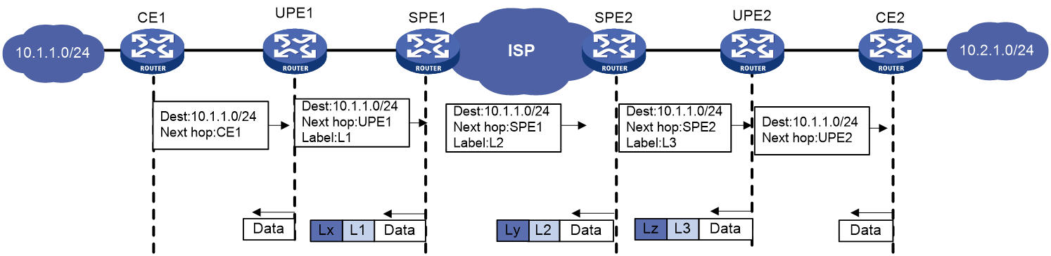
Hierarchy of VPN (HoVPN) divides PEs into underlayer PEs (UPEs) or user-end PEs, and superstratum PEs (SPEs) or service provider-end PEs. UPEs and SPEs form a hierarchical PE structure.
UPEs and SPEs together provide the functions of a conventional PE.
· UPE—Provides user access. It maintains the routes of directly connected VPN sites. It does not maintain the routes of the remote sites in the VPN, or it only maintains their summary routes. A UPE assigns inner labels to the routes of its directly connected sites, and advertises the labels along with VPN routes to the SPE through MP-BGP.
· SPE—Manages and advertises VPN routes. It maintains all the routes of the VPNs connected through UPEs, including the routes of both the local and remote sites. An SPE advertises routes along with labels to UPEs, including the default routes of VPN instances or summary routes and the routes permitted by the routing policy. By using routing policies, you can control which sites in a VPN can communicate with each other.
Figure 1 Routing process and label exchange for HoVPN
Prerequisites
This document is not restricted to specific software or hardware versions.
The configuration examples in this document were created and verified in a lab environment, and all the devices were started with the factory default configuration. When you are working on a live network, make sure you understand the potential impact of every command on your network.
This document assumes that you have basic knowledge of HoVPN.
Example: Configuring HoVPN
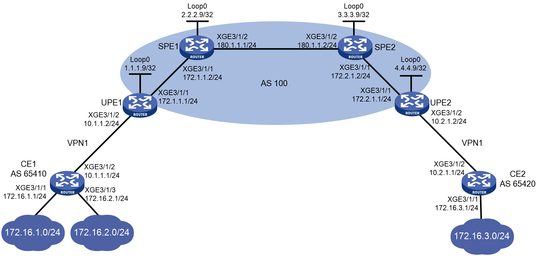
Network configuration
As shown in Figure 2, the SPE devices and UPE devices are in AS 100. The SPEs are ISP backbone devices. The UPEs are connected to the CEs of the user network. CE 1 and CE 2 belong to VPN 1.
Configure HoVPN and advertise default routes to allow communication between CE 1 (172.16.1.0/24 and 172.16.2.0/24) and CE 2 (172.16.3.0/24).
Analysis
To allow communication between CE 1 and CE 2, configure each SPE to advertise the default route of the VPN instance to its peer.
Restrictions and guidelines
Associating an interface with a VPN instance deletes the IP address of the interface. You must reconfigure the IP address of the interface after the association. To avoid configuring the interface's IP address twice, configure the association first.
Procedures
Enable MPLS and MPLS LDP on SPEs, and configure the IGP protocol (OSPF, in this example)
# On SPE 1, configure basic MPLS and MPLS LDP to establish LDP LSPs.
<SPE1> system-view
[SPE1] interface loopback 0
[SPE1-LoopBack0] ip address 2.2.2.9 32
[SPE1-LoopBack0] quit
[SPE1] mpls lsr-id 2.2.2.9
[SPE1] mpls ldp
[SPE1-ldp] quit
[SPE1] interface Ten-GigabitEthernet3/1/1
[SPE1-Ten-GigabitEthernet3/1/1] ip address 172.1.1.2 24
[SPE1-Ten-GigabitEthernet3/1/1] mpls enable
[SPE1-Ten-GigabitEthernet3/1/1] mpls ldp enable
[SPE1-Ten-GigabitEthernet3/1/1] quit
[SPE1] interface Ten-GigabitEthernet3/1/2
[SPE1-Ten-GigabitEthernet3/1/2] ip address 180.1.1.1 24
[SPE1-Ten-GigabitEthernet3/1/2] mpls enable
[SPE1-Ten-GigabitEthernet3/1/2] mpls ldp enable
[SPE1-Ten-GigabitEthernet3/1/2] quit
# On SPE 1, configure OSPF.
[SPE1] ospf
[SPE1-ospf-1] area 0
[SPE1-ospf-1-area-0.0.0.0] network 2.2.2.9 0.0.0.0
[SPE1-ospf-1-area-0.0.0.0] network 180.1.1.0 0.0.0.255
[SPE1-ospf-1-area-0.0.0.0] network 172.1.1.0 0.0.0.255
[SPE1-ospf-1-area-0.0.0.0] quit
[SPE1-ospf-1] quit
# On SPE 2, configure basic MPLS and MPLS LDP to establish LDP LSPs.
<SPE2> system-view
[SPE2] interface loopback 0
[SPE2-LoopBack0] ip address 3.3.3.9 32
[SPE2-LoopBack0] quit
[SPE2] mpls lsr-id 3.3.3.9
[SPE2] mpls ldp
[SPE2-ldp] quit
[SPE2] interface Ten-GigabitEthernet3/1/2
[SPE2-Ten-GigabitEthernet3/1/2] ip address 180.1.1.2 24
[SPE2-Ten-GigabitEthernet3/1/2] mpls enable
[SPE2-Ten-GigabitEthernet3/1/2] mpls ldp enable
[SPE2-Ten-GigabitEthernet3/1/2] quit
[SPE2] interface Ten-GigabitEthernet3/1/1
[SPE2-Ten-GigabitEthernet3/1/1] ip address 172.2.1.2 24
[SPE2-Ten-GigabitEthernet3/1/1] mpls enable
[SPE2-Ten-GigabitEthernet3/1/1] mpls ldp enable
[SPE2-Ten-GigabitEthernet3/1/1] quit
# On SPE 2, configure OSPF.
[SPE2] ospf
[SPE2-ospf-1] area 0
[SPE2-ospf-1-area-0.0.0.0] network 3.3.3.9 0.0.0.0
[SPE2-ospf-1-area-0.0.0.0] network 180.1.1.0 0.0.0.255
[SPE2-ospf-1-area-0.0.0.0] network 172.2.1.0 0.0.0.255
[SPE2-ospf-1-area-0.0.0.0] quit
[SPE2-ospf-1] quit
# Execute the display mpls ldp peer command to verify that an LDP session in Operational state has been established between the SPEs. (Details not shown.)
# Execute the display ospf peer command to verify that an OSPF neighbor relationship in FULL state has been established between the SPEs. (Details not shown.)
Establish an MP-IBGP peer relationship between SPE 1 and SPE 2 to exchange VPNv4 routes
# On SPE 1, establish an MP-IBGP peer relationship with SPE 2.
[SPE1] bgp 100
[SPE1-bgp-default] peer 3.3.3.9 as-number 100
[SPE1-bgp-default] peer 3.3.3.9 connect-interface loopback 0
[SPE1-bgp-default] address-family vpnv4
[SPE1-bgp-default-vpnv4] peer 3.3.3.9 enable
[SPE1-bgp-default-vpnv4] quit
[SPE1-bgp-default] quit
# On SPE 2, establish an MP-IBGP peer relationship with SPE 1.
[SPE2] bgp 100
[SPE2-bgp-default] peer 2.2.2.9 as-number 100
[SPE2-bgp-default] peer 2.2.2.9 connect-interface loopback 0
[SPE2-bgp-default] address-family vpnv4
[SPE2-bgp-default-vpnv4] peer 2.2.2.9 enable
[SPE2-bgp-default-vpnv4] quit
[SPE2-bgp-default] quit
# Execute the display bgp peer vpnv4 command on the SPEs to verify that a BGP peer relationship in Established state has been established. (Details not shown.)
Configure basic MPLS, enable MPLS LDP, and configure OSPF on UPEs
# Configure UPE 1.
<UPE1> system-view
[UPE1] interface loopback 0
[UPE1-LoopBack0] ip address 1.1.1.9 32
[UPE1-LoopBack0] quit
[UPE1] mpls lsr-id 1.1.1.9
[UPE1] mpls ldp
[UPE1-ldp] quit
[UPE1] interface Ten-GigabitEthernet3/1/1
[UPE1-Ten-GigabitEthernet3/1/1] ip address 172.1.1.1 24
[UPE1-Ten-GigabitEthernet3/1/1] mpls enable
[UPE1-Ten-GigabitEthernet3/1/1] mpls ldp enable
[UPE1-Ten-GigabitEthernet3/1/1] quit
[UPE1] ospf
[UPE1-ospf-1] area 0
[UPE1-ospf-1-area-0.0.0.0] network 1.1.1.9 0.0.0.0
[UPE1-ospf-1-area-0.0.0.0] network 172.1.1.0 0.0.0.255
[UPE1-ospf-1-area-0.0.0.0] quit
[UPE1-ospf-1] quit
# Configure UPE 2.
<UPE2> system-view
[UPE2] interface loopback 0
[UPE2-Loopback0] ip address 4.4.4.9 32
[UPE2-Loopback0] quit
[UPE2] mpls lsr-id 4.4.4.9
[UPE2] mpls ldp
[UPE2-ldp] quit
[UPE2] interface Ten-GigabitEthernet3/1/1
[UPE2-Ten-GigabitEthernet3/1/1] ip address 172.2.1.1 24
[UPE2-Ten-GigabitEthernet3/1/1] mpls enable
[UPE2-Ten-GigabitEthernet3/1/1] mpls ldp enable
[UPE2-Ten-GigabitEthernet3/1/1] quit
[UPE2] ospf
[UPE2-ospf-1] area 0
[UPE2-ospf-1-area-0.0.0.0] network 4.4.4.9 0.0.0.0
[UPE2-ospf-1-area-0.0.0.0] network 172.2.1.0 0.0.0.255
[UPE2-ospf-1-area-0.0.0.0] quit
[UPE2-ospf-1] quit
Establish MP-IBGP peer relationships between SPEs and UPEs, and configure HoVPN
# On UPE 1, establish an MP-IBGP peer relationship with SPE 1.
[UPE1] bgp 100
[UPE1-bgp-default] peer 2.2.2.9 as-number 100
[UPE1-bgp-default] peer 2.2.2.9 connect-interface loopback 0
[UPE1-bgp-default] address-family vpnv4
[UPE1-bgp-default-vpnv4] peer 2.2.2.9 enable
# On SPE 1, configure VPN instance vpn1.
[SPE1] ip vpn-instance vpn1
[SPE1-vpn-instance-vpn1] route-distinguisher 100:1
[SPE1-vpn-instance-vpn1] vpn-target 100:1 both
[SPE1-vpn-instance-vpn1] quit
# On SPE 1, establish an MP-IBGP peer relationship with UPE 1, and specify UPE 1 as a UPE.
[SPE1] bgp 100
[SPE1-bgp-default] peer 1.1.1.9 as-number 100
[SPE1-bgp-default] peer 1.1.1.9 connect-interface loopback 0
[SPE1-bgp-default] address-family vpnv4
[SPE1-bgp-default-vpnv4] peer 1.1.1.9 enable
[SPE1-bgp-default-vpnv4] peer 1.1.1.9 upe
[SPE1-bgp-default-vpnv4] quit
[SPE1-bgp-default] ip vpn-instance vpn1
[SPE1-bgp-default-vpn1] address-family ipv4 unicast
[SPE1-bgp-default-ipv4-vpn1] quit
[SPE1-bgp-default-vpn1] quit
[SPE1-bgp-default] quit
# On UPE 2, establish an MP-IBGP peer relationship with SPE 2.
[UPE2] bgp 100
[UPE2-bgp-default] peer 3.3.3.9 as-number 100
[UPE2-bgp-default] peer 3.3.3.9 connect-interface loopback 0
[UPE2-bgp-default] address-family vpnv4
[UPE2-bgp-default-vpnv4] peer 3.3.3.9 enable
# On SPE 2, configure VPN instance vpn1.
[SPE2] ip vpn-instance vpn1
[SPE2-vpn-instance-vpn1] route-distinguisher 100:1
[SPE2-vpn-instance-vpn1] vpn-target 100:1 both
[SPE2-vpn-instance-vpn1] quit
# On SPE 2, establish an MP-IBGP peer relationship with UPE 2, and specify UPE 2 as a UPE.
[SPE2] bgp 100
[SPE2-bgp-default] peer 4.4.4.9 as-number 100
[SPE2-bgp-default] peer 4.4.4.9 connect-interface loopback 0
[SPE2-bgp-default] address-family vpnv4
[SPE2-bgp-default-vpnv4] peer 4.4.4.9 enable
[SPE2-bgp-default-vpnv4] peer 4.4.4.9 upe
[SPE2-bgp-default-vpnv4] quit
[SPE2-bgp-default] ip vpn-instance vpn1
[SPE2-bgp-default-vpn1] address-family ipv4 unicast
[SPE2-bgp-default-ipv4-vpn1] quit
[SPE2-bgp-default-vpn1] quit
[SPE2-bgp-default] quit
# Execute the display bgp peer vpnv4 command on the SPEs and UPEs to verify that a BGP peer relationship in Established state has been established between each SPE and its connected UPE. (Details not shown.)
Allow CE access to UPEs
# On UPE 1, configure VPN instance vpn1 to allow CE 1 to access UPE 1.
[UPE1] ip vpn-instance vpn1
[UPE1-vpn-instance-vpn1] route-distinguisher 100:1
[UPE1-vpn-instance-vpn1] vpn-target 100:1 both
[UPE1-vpn-instance-vpn1] quit
[UPE1] interface Ten-GigabitEthernet3/1/2
[UPE1-Ten-GigabitEthernet3/1/2] ip binding vpn-instance vpn1
[UPE1-Ten-GigabitEthernet3/1/2] ip address 10.1.1.2 24
[UPE1-Ten-GigabitEthernet3/1/2] quit
# On UPE 1, establish an EBGP peer relationship with CE 1, and redistribute VPN routes into BGP.
[UPE1] bgp 100
[UPE1-bgp-default] ip vpn-instance vpn1
[UPE1-bgp-default-vpn1] peer 10.1.1.1 as-number 65410
[UPE1-bgp-default-vpn1] address-family ipv4 unicast
[UPE1-bgp-default-ipv4-vpn1] peer 10.1.1.1 enable
[UPE1-bgp-default-ipv4-vpn1] import-route direct
[UPE1-bgp-default-ipv4-vpn1] quit
[UPE1-bgp-default-vpn1] quit
# On CE 1, establish an EBGP peer relationship with UPE 1, and redistribute direct routes into BGP.
<CE1> system-view
[CE1] interface Ten-GigabitEthernet3/1/2
[CE1-Ten-GigabitEthernet3/1/2] ip address 10.1.1.1 255.255.255.0
[CE1-Ten-GigabitEthernet3/1/2] quit
[CE1] bgp 65410
[CE1-bgp-default] peer 10.1.1.2 as-number 100
[CE1-bgp-default] address-family ipv4 unicast
[CE1-bgp-default-ipv4] peer 10.1.1.2 enable
[CE1-bgp-default-ipv4] import-route direct
[CE1-bgp-default-ipv4] quit
[CE1-bgp-default] quit
# On UPE 2, configure VPN instance vpn1 to allow CE 2 to access UPE 2.
[UPE2] ip vpn-instance vpn1
[UPE2-vpn-instance-vpn1] route-distinguisher 100:1
[UPE2-vpn-instance-vpn1] vpn-target 100:1 both
[UPE2-vpn-instance-vpn1] quit
[UPE2] interface Ten-GigabitEthernet3/1/2
[UPE2-Ten-GigabitEthernet3/1/2] ip binding vpn-instance vpn1
[UPE2-Ten-GigabitEthernet3/1/2] ip address 10.2.1.2 24
[UPE2-Ten-GigabitEthernet3/1/2] quit
# On UPE 2, establish an EBGP peer relationship with CE 2, and redistribute VPN routes into BGP.
[UPE2] bgp 100
[UPE2-bgp-default] ip vpn-instance vpn1
[UPE2-bgp-default-vpn1] peer 10.2.1.1 as-number 65420
[UPE2-bgp-default-vpn1] address-family ipv4 unicast
[UPE2-bgp-default-ipv4-vpn1] peer 10.2.1.1 enable
[UPE2-bgp-default-ipv4-vpn1] import-route direct
[UPE2-bgp-default-ipv4-vpn1] quit
[UPE2-bgp-default-vpn1] quit
# On CE 2, establish an EBGP peer relationship with UPE 2, and redistribute direct routes into BGP.
<CE2> system-view
[CE2] interface Ten-GigabitEthernet3/1/2
[CE2-Ten-GigabitEthernet3/1/2] ip address 10.2.1.1 255.255.255.0
[CE2-Ten-GigabitEthernet3/1/2] quit
[CE2] bgp 65420
[CE2-bgp-default] peer 10.2.1.2 as-number 100
[CE2-bgp-default] address-family ipv4 unicast
[CE2-bgp-default-ipv4] peer 10.2.1.2 enable
[CE2-bgp-default-ipv4] import-route direct
[CE2-bgp-default-ipv4] quit
[CE2-bgp-default] quit
# Execute the display bgp peer ipv4 command on the UPEs and CEs to verify that a BGP peer relationship in Established state has been established between each UPE and its connected CE. (Details not shown.)
Configure default routes to allow CE 1 and CE 2 to communicate with each other
# On SPE 1, advertise the default route of the VPN instance to UPE 1.
[SPE1] bgp 100
[SPE1-bgp] address-family vpnv4
[SPE1-bgp-vpnv4] peer 1.1.1.9 default-route-advertise vpn-instance vpn1
# On SPE 2, advertise the default route of the VPN instance to UPE 2.
[SPE2] bgp 100
[SPE2-bgp-default] address-family vpnv4
[SPE2-bgp-default-vpnv4] peer 4.4.4.9 default-route-advertise vpn-instance vpn1
# Configure a default route on CE 1.
[CE1] ip route-static 0.0.0.0 0 10.1.1.2
# Configure a default route on CE 2.
[CE2] ip route-static 0.0.0.0 0 10.2.1.2
Verifying the configuration
# Verify that CE 1 has learned the route to subnet 172.16.3.0/24 of CE 2.
[CE1] display ip routing-table
Destinations : 25 Routes : 25
Destination/Mask Proto Pre Cost NextHop Interface
0.0.0.0/0 Static 60 0 10.1.1.2 XGE3/1/2
172.16.1.0/24 Direct 0 0 172.16.1.1 XGE3/1/1
172.16.1.0/32 Direct 0 0 172.16.1.1 XGE3/1/1
172.16.1.1/32 Direct 0 0 127.0.0.1 InLoop0
172.16.1.255/32 Direct 0 0 172.16.1.1 XGE3/1/1
172.16.2.0/24 Direct 0 0 172.16.2.1 XGE3/1/3
172.16.2.0/32 Direct 0 0 172.16.2.1 XGE3/1/3
172.16.2.1/32 Direct 0 0 127.0.0.1 InLoop0
172.16.2.255/32 Direct 0 0 172.16.2.1 XGE3/1/3
CE 1-connected networks (172.16.1.0/24 and 172.16.2.0/24) and CE 2-connected network (172.16.3.0/24) can communicate with each other.
Configuration files
· CE 1:
#
interface Ten-GigabitEthernet3/1/1
ip address 172.16.1.1 255.255.255.0
#
interface Ten-GigabitEthernet3/1/2
ip address 10.1.1.1 255.255.255.0
#
interface Ten-GigabitEthernet3/1/1
ip address 172.16.2.1 255.255.255.0
#
bgp 65410
peer 10.1.1.2 as-number 100
#
address-family ipv4 unicast
import-route direct
peer 10.1.1.2 enable
#
ip route-static 0.0.0.0 0 10.1.1.2
· CE 2:
#
interface Ten-GigabitEthernet3/1/1
ip address 172.16.3.1 255.255.255.0
#
interface Ten-GigabitEthernet3/1/2
ip address 10.2.1.1 255.255.255.0
#
bgp 65420
peer 10.2.1.2 as-number 100
#
address-family ipv4 unicast
import-route direct
peer 10.2.1.2 enable
#
ip route-static 0.0.0.0 0 10.2.1.2
· UPE 1:
#
ip vpn-instance vpn1
route-distinguisher 100:1
vpn-target 100:1 import-extcommunity
vpn-target 100:1 export-extcommunity
#
ospf 1
area 0.0.0.0
network 1.1.1.9 0.0.0.0
network 172.1.1.0 0.0.0.255
#
mpls lsr-id 1.1.1.9
#
mpls ldp
#
interface LoopBack0
ip address 1.1.1.9 255.255.255.255
#
interface Ten-GigabitEthernet3/1/1
ip address 172.1.1.1 255.255.255.0
mpls enable
mpls ldp enable
#
interface Ten-GigabitEthernet3/1/2
ip binding vpn-instance vpn1
ip address 10.1.1.2 255.255.255.0
#
bgp 100
peer 2.2.2.9 as-number 100
peer 2.2.2.9 connect-interface LoopBack0
#
address-family vpnv4
peer 2.2.2.9 enable
#
ip vpn-instance vpn1
peer 10.1.1.1 as-number 65410
#
address-family ipv4 unicast
import-route direct
peer 10.1.1.1 enable
#
· SPE 1:
#
ip vpn-instance vpn1
route-distinguisher 100:1
vpn-target 100:1 import-extcommunity
vpn-target 100:1 export-extcommunity
#
ospf 1
area 0.0.0.0
network 2.2.2.9 0.0.0.0
network 180.1.1.0 0.0.0.255
network 172.1.1.0 0.0.0.255
#
mpls lsr-id 2.2.2.9
#
mpls ldp
#
interface LoopBack0
ip address 2.2.2.9 255.255.255.255
#
interface Ten-GigabitEthernet3/1/1
ip address 172.1.1.2 255.255.255.0
mpls enable
mpls ldp enable
#
interface Ten-GigabitEthernet3/1/2
ip address 180.1.1.1 255.255.255.0
mpls enable
mpls ldp enable
#
bgp 100
peer 1.1.1.9 as-number 100
peer 1.1.1.9 connect-interface LoopBack0
peer 3.3.3.9 as-number 100
peer 3.3.3.9 connect-interface LoopBack0
#
address-family vpnv4
peer 1.1.1.9 enable
peer 1.1.1.9 upe
peer 1.1.1.9 default-route-advertise vpn-instance vpn1
peer 3.3.3.9 enable
#
ip vpn-instance vpn1
#
address-family ipv4 unicast
#
· UPE 2:
#
ip vpn-instance vpn1
route-distinguisher 100:1
vpn-target 100:1 import-extcommunity
vpn-target 100:1 export-extcommunity
#
ospf 1
area 0.0.0.0
network 4.4.4.9 0.0.0.0
network 172.2.1.0 0.0.0.255
#
mpls lsr-id 4.4.4.9
#
mpls ldp
#
interface LoopBack0
ip address 4.4.4.9 255.255.255.255
#
interface Ten-GigabitEthernet3/1/1
ip address 172.2.1.1 255.255.255.0
mpls enable
mpls ldp enable
#
interface Ten-GigabitEthernet3/1/2
ip binding vpn-instance vpn1
ip address 10.2.1.2 255.255.255.0
#
bgp 100
peer 3.3.3.9 as-number 100
peer 3.3.3.9 connect-interface LoopBack0
#
address-family vpnv4
peer 3.3.3.9 enable
#
ip vpn-instance vpn1
peer 10.2.1.1 as-number 65420
#
address-family ipv4 unicast
import-route direct
peer 10.2.1.1 enable
#
· SPE 2:
#
ip vpn-instance vpn1
route-distinguisher 100:1
vpn-target 100:1 import-extcommunity
vpn-target 100:1 export-extcommunity
#
ospf 1
area 0.0.0.0
network 3.3.3.9 0.0.0.0
network 180.1.1.0 0.0.0.255
network 172.2.1.0 0.0.0.255
#
mpls lsr-id 3.3.3.9
#
mpls ldp
#
interface LoopBack0
ip address 3.3.3.9 255.255.255.255
#
interface Ten-GigabitEthernet3/1/1
ip address 172.2.1.2 255.255.255.0
mpls enable
mpls ldp enable
#
interface Ten-GigabitEthernet3/1/2
ip address 180.1.1.2 255.255.255.0
mpls enable
mpls ldp enable
#
bgp 100
router-id 3.3.3.9
peer 2.2.2.9 as-number 100
peer 2.2.2.9 connect-interface LoopBack0
peer 4.4.4.9 as-number 100
peer 4.4.4.9 connect-interface LoopBack0
#
address-family vpnv4
peer 2.2.2.9 enable
peer 4.4.4.9 enable
peer 4.4.4.9 upe
peer 4.4.4.9 default-route-advertise vpn-instance vpn1
#
ip vpn-instance vpn1
#
address-family ipv4 unicast
#
Related documentation
· H3C SR8800-X Routers MPLS Configuration Guide
· H3C SR8800-X Routers MPLS Command Reference
