- Table of Contents
-
- H3C UniServer B16000 Blade Server Configuration Examples-6W101
- 01-FC and FCoE Services Configuration Examples
- 02-Ethernet Services Configuration Examples
- 03-Virtual Management Network Configuration Examples
- 04-Shared Storage Configuration Examples
- 05-VC Configuration Examples
- 06-Chassis Profile Configuration Examples
- 07-IB Service Configuration Examples
- 08-Blade Server FIST Configuration Examples
- Related Documents
-
| Title | Size | Download |
|---|---|---|
| 04-Shared Storage Configuration Examples | 1.32 MB |
Example: Configuring SAS shared storage
Creating a storage partition and mounting it to the blade server
Configuring RAID under blade server BIOS
Verifying the configuration under the BIOS of the blade server
Introduction
The following information provides examples for configuring SAS shared storage for the H3C UniServer B16000 blade server chassis.
Hardware compatibility
Table 1 lists the hardware to be used in the typical networking of SAS shared storage.
Table 1 Hardware compatibility
|
Configuration example |
Hardware compatibility |
||||
|
Rear Mezz RAID card |
HDD bay |
Interconnect module |
|||
|
Disk |
Expander card |
HDD bay pass-through mezzanine card |
|||
|
Example: Configuring SAS shared storage |
RAID-P5408-Ma-8i-4GB |
SAS drive |
SXP-40SAS |
PTH-PT108-Mb-S1 |
BX500S |
|
RAID-P4408-Ma-8i-2GB |
SAS drive SATA drive SAS/SATA drive |
||||
Prerequisites
The configuration examples were created and verified in a lab environment, and all the devices were started with the factory default configuration. When you are working on a live network, make sure you understand the potential impact of every command on your network.
Before using this manual, you need to have the following knowledge:
· Understand the basic operations of OM.
· Understand the SAS shared storage.
Example: Configuring SAS shared storage
Network configuration
As shown in Figure 1, the following modules are installed in the H3C B16000 blade server chassis:
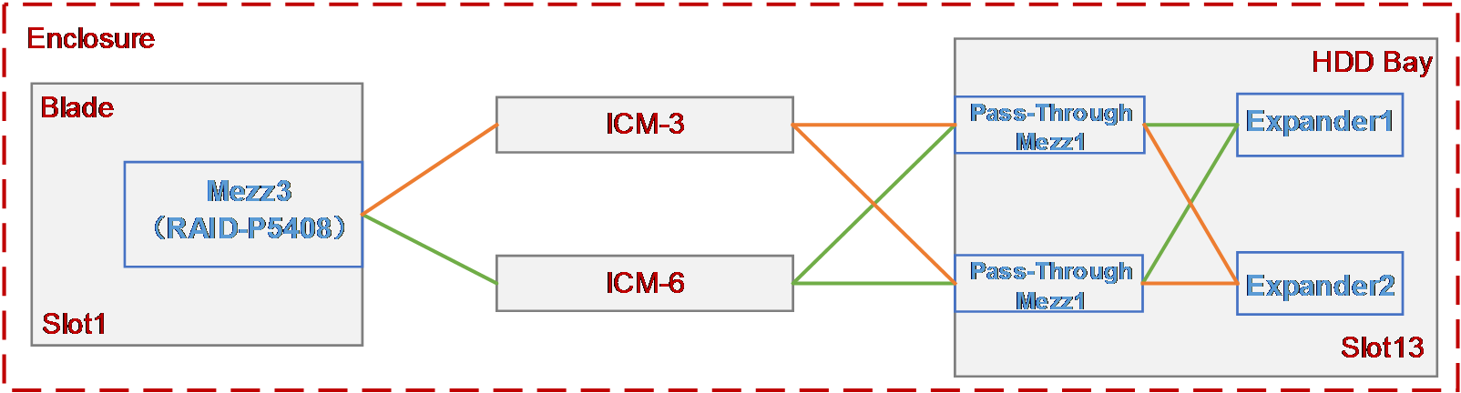
· The blade server (model: H3C UniServer B5700 G3) is installed in slot 1. The rear Mezz RAID card (model: RAID-P5408-Ma-8i-4GB) is installed in the mezzanine card slot 3 of the blade server.
· The HDD bay is installed in slot 13. There are 11 drives in the bay, and the full configuration includes two Expander cards (model: SXP-40SAS) and two HDD bay pass-through mezzanine cards (model: PTH-PT108-Mb-S1) to form a physical dual link.
· Two SAS switch modules (model: H3C UniServer BX500S) are respectively installed in interconnect module slot 3 and interconnect module slot 6 for mutual backup.
The following requirements are expected to be met:
· Select four drives on the HDD bay to mount to the blade server in slot 1, and use two of them to form the RAID0 (named as SAS RAID).
· The service will not be affected when any SAS switch module or Expander card fails.
Analysis
· To mount the drives in the HDD bay to the blade server, you need to build the physical link between the blade server and the HDD bay first, that is, the HDD bay, SAS switch module and the blade server must be present at the same time. Among them, Expander cards and HDD bay pass-through mezzanine cards must be installed in the HDD bay, and the rear Mezz RAID cards must be installed in the blade server. Select four drives (here we use the drives in slots 0, 3, 5 and 10 as an example) in the HDD bay through the OM, and create a storage partition and associate it to the blade server. Then, the HDD bay can be automatically mounted to the blade server.
· To use the mounted drives to create the RAID0, you must select two mounted drives (here we use the drives in slots 0 and 3 as an example) to create the RAID0 using the rear Mezz RAID card controller of the blade server through the BIOS of the server.
· To ensure service continuity when any SAS switch module or Expander card fails, you must install two Expander cards in the Expander slots 1 and 2 on the HDD bay, install two HDD bay pass-through mezzanine cards in HDD bay mezzanine card slots 1 and 2, and install two SAS switch modules in the interconnect module slots 3 and 6.
Software versions used
This configuration example was created and verified on the following versions.
· OM management module: OM-1.01.14.
· SAS switch module: SWITCH_SYS-1.02.11.
Configuration precautions
· The rear Mezz RAID card must be installed in mezzanine card slot 3 or slot 6 on the blade server. If only one rear Mezz RAID card is configured, it is recommended to install it in mezzanine card slot 3 of the blade server.
· When installing different types of drives in the HDD bay, the quantity and positions of Expander cards and SAS switch modules vary. Refer to the following guidelines for actual configuration:
¡ When SAS drives are installed in the HDD bay, install two Expander cards, and install one or two SAS switch modules (optional) in the interconnect module slot 3 or slot 6.
¡ When SATA drives are installed in the HDD bay and the HDD bay quantity is one, you can only install one Expander card, and install one or two SAS switch modules (optional) in interconnect module slot 3 or slot 6. When one SAS switch module is installed, you must install the blade server and the HDD bay on the same side (left side or right side when you stand in front of the chassis). When they are installed on the left side, the SAS switch module must be installed in interconnect module slot 6. When they are installed on the right side, the SAS switch module must be installed in interconnect module slot 3.
¡ When SATA drives are installed in the HDD bay and the HDD bay quantity is greater than one, you can install two Expander cards, and install two SAS switch modules in interconnect module slot 3 and slot 6.
¡ When both SAS and SATA drives are installed in the HDD bay, install two Expander cards, and install two SAS switch modules in the interconnect module slot 3 and slot 6, respectively.
Procedures
Creating a storage partition and mounting it to the blade server
1. On the OM Web page, click Storage Management > Create.
2. Perform the following actions in a certain order:
a. On the parameter column of Please select blade server, select the blade server in slot 1.
b. In the Please select HDD Bay view, select HDD bay in slot 13.
c. In the Please select a disk view, select 4 drives in slots 0, 3, 5, and 10.
d. Click Apply to create the storage partition and mount the drives to the blade server.
3. After the storage partition is created, the system will prompt that the creation is successful.
Configuring RAID under blade server BIOS
Entering the BIOS page of the blade server
1. On the OM Web page, click Blade server management > Select the blade server 1, click Remote Console > H5 KVM to log in to blade server 1.
2. When the blade server is booting, press Esc as prompted to enter the BIOS setup page, as shown in Figure 2.

Configure an RAID
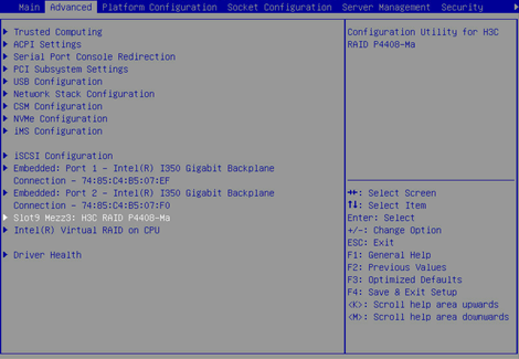
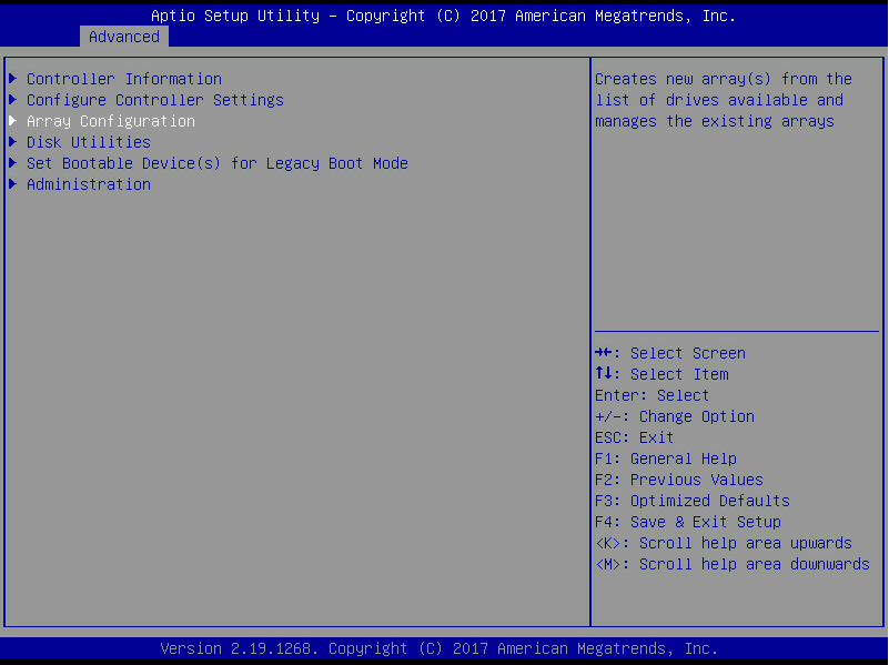
1. As shown in Figure 3, enter the Advanced page, select the rear Mezz RAID card of RAID P4408-Ma, and press Enter to enter the management page of the card.

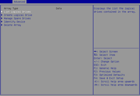
2. Enter the storage controller card configuration screen shown in Figure 4, select Array Configuration, and press Enter.
Figure 4 Storage controller card configuration screen

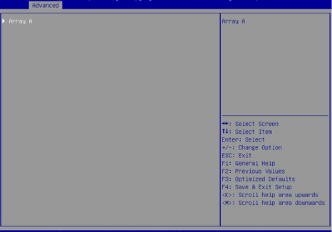
3. Enter the screen as shown in Figure 5, select Create Array and press Enter.
Figure 5 Selecting Create Array

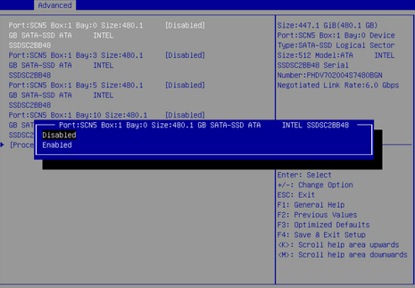
4. Enter the page shown in Figure 6, and select the drives to be used for creating the RAID. Enabled indicates that the drive is selected. Select the drives in slots 0, 3, 5 and 10 in sequence. Then, select Proceed to next Form and press Enter.
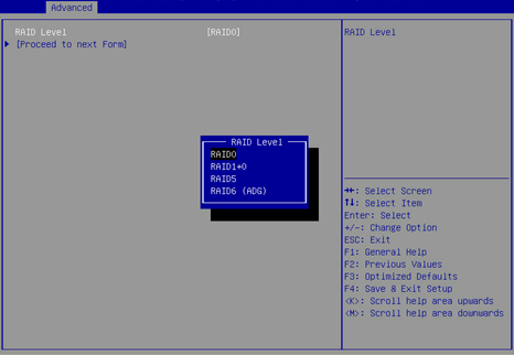
5. Enter the screen shown in Figure 7, set the RAID level to RAID0 in the RAID Level column. Then, select Proceed to next Form and press Enter.
Figure 7 Setting the RAID level
6. Enter the screen shown in Figure 8. Set the parameters of Logical Drive Label, Stripe Size/Full Stripe Size, Size, Unit Size and Acceleration Method (for description of the parameters, see Table 2). Then, select Submit Changes and press Enter.
Figure 8 Setting relevant parameters
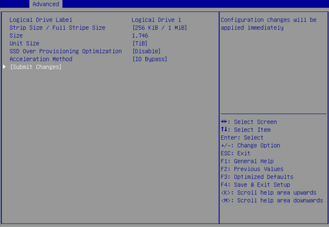
|
Parameter |
Remarks |
|
Logical Drive Label |
The name of the RAID |
|
Stripe Size/Full Stripe Size |
Stripe size, the size of the stripe blocks written on each disk |
|
Size |
The capacity of the logical drive |
|
Unit Size |
The unit size |
|
Acceleration Method |
The cache mode of the logical drive |
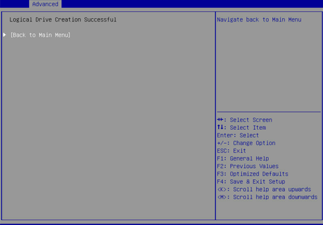
7. After the RAID configuration is complete, select Back to Main Menu, and press Enter to return to the rear Mezz RAID card configuration page.
Figure 9 The RAID configuration is complete
Verifying the configuration
Verifying the configuration under the BIOS of the blade server
1. On the OM Web page, click Blade server management > Select the blade server 1, click Remote Console > H5 KVM to log in to blade server 1.
2. When the blade server is booting, press Esc as prompted to enter the BIOS setup page, as shown in Figure 10.
3. As shown in Figure 11, enter the Advanced page, select the rear Mezz RAID card of RAID P4408-Ma, and press Enter to enter the management page of the card.
4. Enter the storage controller card configuration screen shown in Figure 12, select Array Configuration, and press Enter.
Figure 12 Storage controller card configuration screen
5. Select Manage Arrays and press Enter to enter the screen shown in Figure 13. Then, select the RAID to be viewed and press Enter.
Figure 13 Selecting the RAID to be viewed
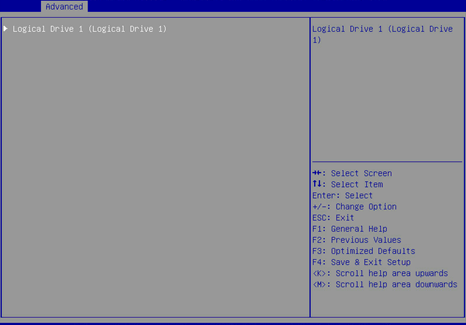
6. Enter the screen shown in Figure 14, select List Logical Drives, select the RAID to be viewed, and press Enter.
Figure 14 Selecting List Logical Drives
7. Enter the screen shown in Figure 15, select Logical Drive 1, and press Enter.
Figure 15 Selecting Logical Drive 1
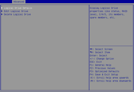
8. Enter the screen shown in Figure 16, select Logical Drive Details, and press Enter.
Figure 16 Selecting Logical Drive Details
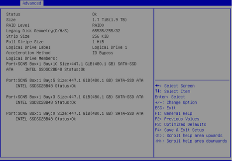
9. Enter the screen shown in Figure 17 to view the RAID details (including RAID name, level, and disk information).