- Table of Contents
-
- H3C UniServer B16000 Blade Server Configuration Examples-6W101
- 01-FC and FCoE Services Configuration Examples
- 02-Ethernet Services Configuration Examples
- 03-Virtual Management Network Configuration Examples
- 04-Shared Storage Configuration Examples
- 05-VC Configuration Examples
- 06-Chassis Profile Configuration Examples
- 07-IB Service Configuration Examples
- 08-Blade Server FIST Configuration Examples
- Related Documents
-
| Title | Size | Download |
|---|---|---|
| 01-FC and FCoE Services Configuration Examples | 4.37 MB |
Contents
Example: Configuring FC (connecting FC switch module to FC switch)
Configuring the mezzanine card
Configuring the Brocade switch
Configuring the interconnect module
Example: Configuring FC (uplinking multiple ports of the FC switch module to FC switch)
Querying the port connection relation between mezzanine cards and interconnect modules
Configuring the mezzanine card
Configuring the interconnect module
Configuring the Brocade switch
Verifying load balancing of ports on FC switch modules
Accessing virtual volumes by the system through multiple paths
Example: Configuring FC (uplinking the aggregation interfaces of FC switch modules to FC switches)
Query the port connection between mezzanine cards and interconnect modules
Configuring the mezzanine card
Configuring the interconnect module
Verifying the configuration of the FC aggregation group
Accessing virtual volumes by the system through multiple paths
Example: Configuring FC (directly connecting FC switch modules to the 3Par storage)
Configuring the mezzanine card
Configuring the interconnect module
Example: Configuring FCoE (connecting aggregation interconnect modules to FC switches)
Configuring the mezzanine card
Configuring the interconnect module
Configuring the Brocade switch
Configuring the mezzanine card
Configuring the aggregation interconnect module
Configuring the H3C S6800 switch
Verifying the configuration of the aggregation group
Enabling the NPAR function of the mezzanine card
Configuring the mezzanine card
Configuring storage services of the aggregation switch module
Configuring the Brocade switch
Configuring Ethernet services of the aggregation switch module
Configuring the aggregation switch
Example: Configuring FCoE (directly connecting the aggregation interconnect modules to 3Par storage)
Configuring the mezzanine card
Configuring the interconnect module
Example: Configuring FCoE (pass-through modules)
Configuring the mezzanine card
Example: Configuring FC pass-through modules (connecting FC pass-through module to FC switch)
Configuring the mezzanine card
Configuring the Brocade switch
Configuring multipath and adding network disks on Windows Server
Compatibility between the storage of different models and the blade server
Introduction
The following information provides examples for configuring FC and FCoE services for the H3C UniServer B16000 blade server chassis.
Hardware compatibility
Table 1 lists the hardware to be used in typical networking modes. If there are multiple models in a cell, the hardware of these models is appropriate for this configuration.
|
|
IMPORTANT: Red Hat 8.x has deleted the modules supporting FCoE. Therefore, if Red Hat 8.x is installed on the server as its operating system (OS), the FCoE function of the mezzanine card is unavailable. |
Table 1 Hardware compatibility
Prerequisites
The configuration examples were created and verified in a lab environment, and all the devices were started with the factory default configuration. When you are working on a live network, make sure you understand the potential impact of every command on your network.
The following information is provided based on the assumption that you have basic knowledge of FC, FCoE, port aggregation features, H3C blade servers, interconnect modules, Windows/Linux/ESXi/CAS operating systems, Brocade switches, and 3Par storage.
The following information mainly describes the procedure for configuring the blade server chassis. As a best practice, configure external network settings as needed.
Example: Configuring FC (connecting FC switch module to FC switch)
Network requirement
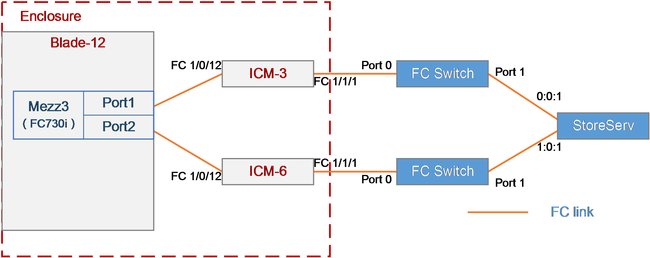
As shown in Figure 1, a blade server and two FC switch modules are installed in the H3C B16000 blade server chassis. The blade server is installed in slot 12, the two FC switch modules are installed in slot 3 and slot 6, and the mezzanine card is installed in the mezzanine card slot 3 of the blade server. The FC 1/1/1 port of each of the two FC switch modules is connected to an FC switch, and the FC switch is connected to the FC storage device through the 0:0:1 port.
In this example, the following devices and modules are used: blade server (H3C UniServer B5700 G3), mezzanine card (NIC-FC730i-Mb-2*32G, "FC730i"), FC switch module (BX608FE), FC switch (Brocade 6510), and FC storage device (H3C CF8840 from the HPE 3Par StoreServ family).
The following requirements are expected to be met:
The OS on the blade server can mount storage volumes on the 3Par to realize remote storage, and data on the 3Par can be accessed through the OS when any interconnect module fails.
Figure 1 Network diagram between FC switch module (NPV mode) and FC switch
Analysis
· To mount a 3Par storage volume under the OS, build an FC link between the blade server and the 3Par storage, and create a storage volume on the 3Par storage. Then, the OS can automatically identify the storage volume.
· In this example, the FC switch module is directly connected to the FC switch, and then connects to the 3Par storage through the FC switch. In this case, you need to configure the mode of the two FC switch modules to NPV.
· To ensure service continuity when any interconnect module fails, you need to configure the multipath function under the OS to improve network reliability.
· As a best practice, connect two interconnect modules to two different FC switches respectively for link redundancy, thus avoiding network disconnection caused by FC switch failure.
Software versions used
This example was created and verified on versions SWITCH_SYS-1.00.11 and OM-1.00.11 of interconnect modules.
Configuration precautions
· Before adding a storage volume, ensure that the blade server has installed the OS and the appropriate network adapter driver, so that the OS can identify the FC730i network adapter correctly. For details about installing the OS, see H3C Servers Operating System Installation Guide. For details about installing the network adapter driver, see FC730i Mezzanine Card Module User Guide.
· After mounting the storage volumes and replacing existing storage volumes on the 3Par with new ones, reboot the OS of the blade server to identify the new volumes.
Procedures
Querying port information
Query the connection relationship between the internal ports of the mezzanine card and interconnect modules according to "Querying port relations."
It can be seen that the FC 1/0/12 ports of the interconnect module 3 and interconnect module 6 are used in this example.
Configuring the mezzanine card
In the FC networking, the FC mezzanine card can be used correctly after being installed in place. There are no other special requirements in this example, so you do not need to configure the mezzanine card.
Configuring the Brocade switch
In this example, the Brocade switch uses the default settings. Ensure that Port 0 and Port 1 reside in the same FC zone.
Configuring the interconnect module
Configuring interconnect module 3
|
|
IMPORTANT: The internal port of the BX608FE interconnect module is in the shutdown state by default. Therefore, when configuring the module for the first time or restoring the default configuration file, execute the undo shutdown command to enable the corresponding port before configuring. Determine the internal port to which the mezzanine card port is connected according to "Querying port relations." |
# Configure the FCoE mode of the switch to NPV.
<H3C> system-view
[H3C] fcoe-mode npv
# Create the VSAN. In this example, create VSAN 1.
[H3C] vsan 1
[H3C-vsan1] quit
# Create the VLAN to map VSAN. In this example, create VLAN 10, enable the FCoE function on VLAN 10, and map the VLAN to VSAN 1.
[H3C] vlan 10
[H3C-vlan10] fcoe enable vsan 1
[H3C-vlan10] quit
# Configure the port connected to the Brocade switch to operate in the NP mode.
[H3C] interface fc1/1/1
[H3C-Fc1/1/1] fc mode np
[H3C-Fc1/1/1] quit
# Save the configuration.
[H3C] save
The current configuration will be written to the device. Are you sure? [Y/N]:y
Please input the file name(*.cfg)[flash:/startup.cfg]
(To leave the existing filename unchanged, press the enter key):
Configuring interconnect module 6
|
|
IMPORTANT: Type IMPORTANT text here. The internal port of the BX608FE interconnect module is in the shutdown state by default. Therefore, when configuring for the first time or restoring the default configuration file, execute the undo shutdown command to enable the corresponding port before configuring. Determine the internal port to which the mezzanine card port is connected according to "Querying port relations." |
# Configure the FCoE mode of the switch to NPV.
<H3C> system-view
[H3C] fcoe-mode npv
# Create the VSAN. In this example, create VSAN 2.
[H3C] vsan 2
[H3C-vsan2] quit
# Create the VLAN to map VSAN. In this example, create VLAN 20, enable the FCoE function on VLAN 20, and map the VLAN to VSAN 2.
[H3C] vlan 20
[H3C-vlan20] fcoe enable vsan 2
[H3C-vlan20] quit
# Configure the port connected to BROCADE switches to operate in NP mode.
[H3C] interface fc1/1/1
[H3C-Fc1/1/1] fc mode np
[H3C-Fc1/1/1] port access vsan 2
[H3C-Fc1/1/1] quit
# Add the internal port to VSAN 2.
[H3C] interface fc1/1/1
[H3C-Fc1/0/12] port access vsan 2
[H3C-Fc1/1/1] quit
# Save the configuration.
[H3C] save
The current configuration will be written to the device. Are you sure? [Y/N]:y
Please input the file name(*.cfg)[flash:/startup.cfg]
(To leave the existing filename unchanged, press the enter key):
Querying the WWN number of the mezzanine card
Execute the display npv login command on the FC switch module to view the registration information about the node device (mezzanine card) connected to the downlink port of the FC switch module and the mapped uplink port. Here we use viewing the FC switch module 3 as an example:
<H3C>display npv login
Server External
Interface VSAN FCID Node WWN Port WWN Interface
Fc1/0/12 1 0x020101 20:00:f4:e9:D4:53:f1:c5 21:00:f4:e9:D4:53:f1:c5 Fc1/1/1
Table 2 Description of the information displayed by executing the display npv login command
|
Field |
Description |
|
Server Interface |
The name of the downlink port |
|
VSAN |
The VSAN number |
|
FCID |
The FC address of the node |
|
Node WWN |
The WWN of the node |
|
Port WWN |
The WWN of the node port |
|
External Interface |
The name of the uplink port to which the downlink port is mapped |
Configuring 3Par storage
See "Configuring 3Par storage" for the process of configuring 3Par storage.
Configuring the OS
|
|
IMPORTANT: · The following information provides the procedure for configuring multipath under Red Hat 7.5. Multipath can realize the loading balancing and reliability of the traffic between hosts and storage devices. For the procedure for configuring multipath and verifying the configuration under Windows, see "Configuring multipath and adding network disks on Windows Server." · Before configuration, ensure that the OS has installed the multipath tool, a built-in tool of most Linux systems. |
Prerequisites
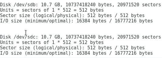
Execute the fdisk -l command under the OS to view the two virtual volumes identified by the host, as shown in Figure 2.
Figure 2 Identifying the virtual volumes

|
|
NOTE: If no disk is found, execute the echo 1 > /sys/class/fc_host/hostnum/issue_lip command to manually refresh fc_host, where hostnum indicates the host number under the /sys/class/fc_host directory, such as host 1. |
Configuring multipath
1. Execute the following commands in turn to load the multipath server, set the polling mode, enable the multipath service, and format the path.
# modprobe dm-multipath
# modprobe dm-round-robin
# systemctl start multipathd.service
# multipath –v2
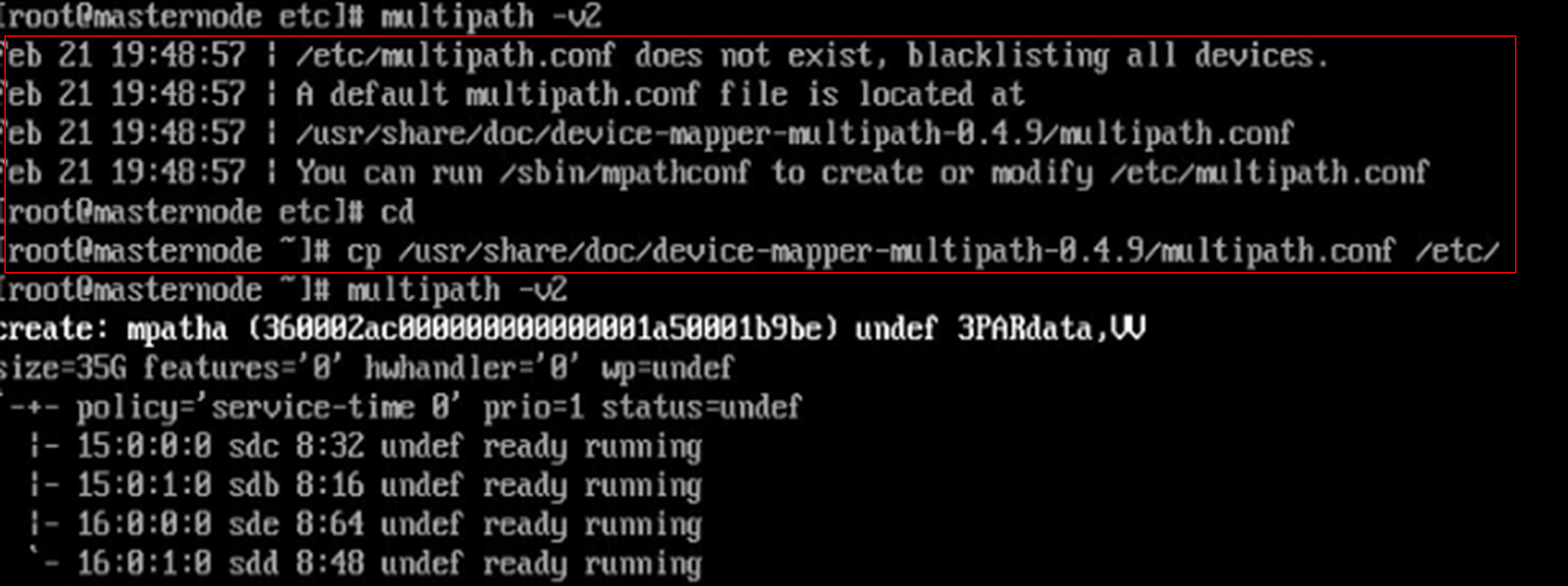
|
|
NOTE: If it is prompted that the multipath.conf file does not exist under the Red Hat operating system, you can copy the file from another location and deliver it again, as shown in Figure 3. |
Figure 3 Handling the case when the multipath.conf file does not exist

2. Execute the following command to reboot the multipath server.
# systemctl restart multipathd.service
3. Run the following command to view the multipath link status, and you can see that the two ports are in the active state, as shown in Figure 4.
# multipath –ll
Figure 4 Viewing the multipath link status

Verifying the configuration
After configuring the multipath, execute the fdisk -l command again. You can see a new mpatha volume, indicating that the system can access virtual volumes through multiple paths, as shown in Figure 5.
Figure 5 Viewing the mpatha volume

Example: Configuring FC (uplinking multiple ports of the FC switch module to FC switch)
Network requirement
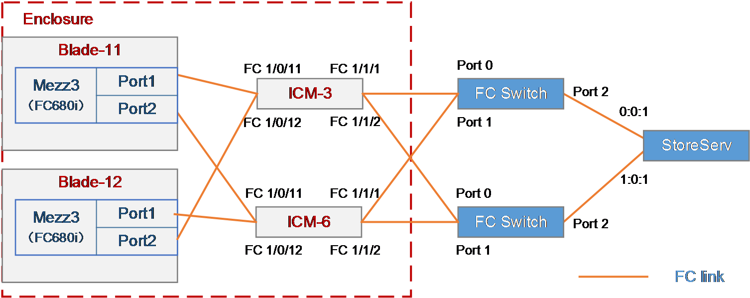
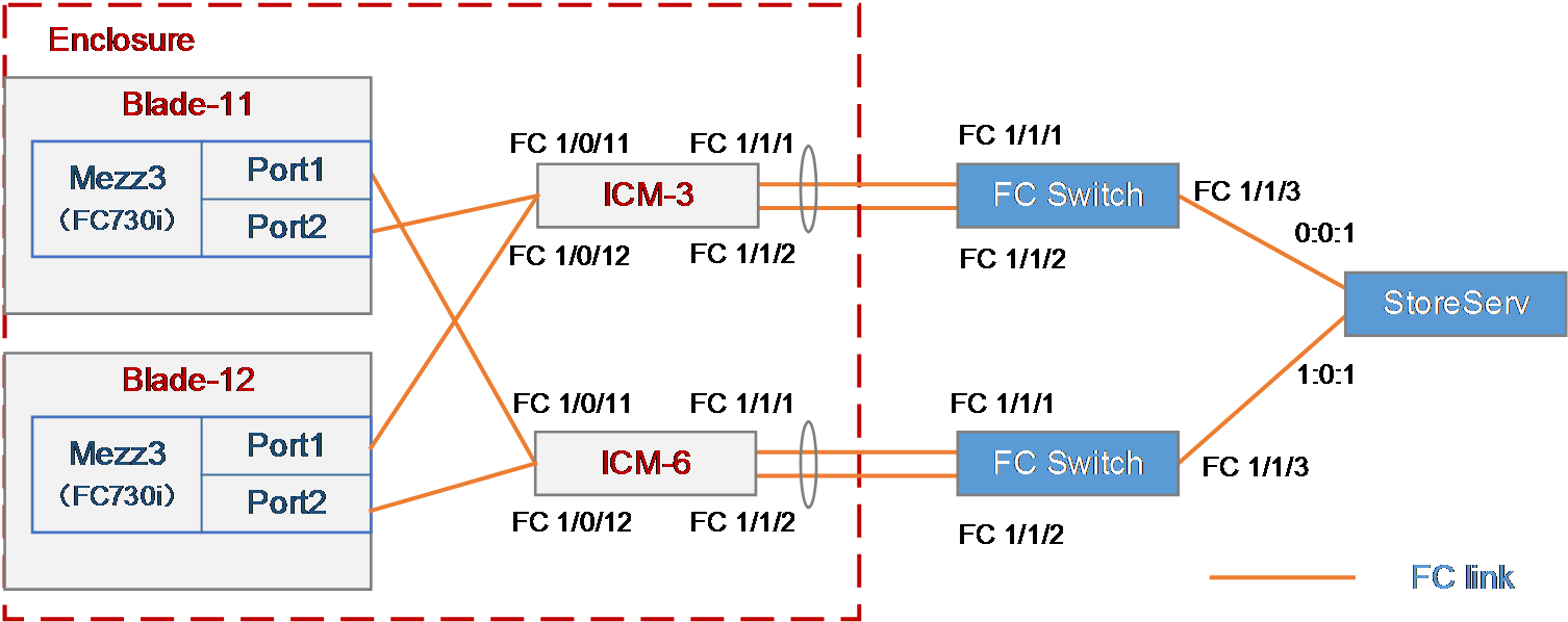
As shown in Figure 6, two blade servers and two FC switch modules are installed in the H3C B16000 blade server chassis.
· The two blade servers are installed in slot 11 and slot 12, respectively.
· The two FC switch modules are installed in slot 3 and slot 6, respectively.
· An FC mezzanine card is installed in the mezzanine card slot 3 of the blade server.
· The FC 1/1/1 and FC 1/1/2 ports of the two FC switch modules are directly connected to Port 0 and Port 1 of the two FC switches.
· Port 2 of each of the two FC switches is directly connected to the 0:0:1 or 1:0:1 port of the FC storage device.
In this example, the following devices and modules are used: blade server (H3C UniServer B5700 G3), mezzanine card (NIC-FC730i-Mb-2*32G, "FC730i"), FC switch module (BX608FE), FC switch (Brocade 6510), and FC storage device (H3C CF8840 from the HPE 3Par StoreServ family).
The following requirements are expected to be met:
· Mounts storage volumes on the 3Par storage to the blade server to realize remote storage.
· Realizes the load balancing of the traffic from multiple ports of the FC switch modules.
· Ensures network reliability so the service is not affected when any FC switch or FC switch module fails.
Figure 6 Network diagram of uplinking multiple ports of FC switch modules in NPV mode to SAN
Key steps
· To mount 3Par storage volumes to the blade server, you need to build an FC link between the blade server and the 3Par storage to enable the transmission of FC traffic, which requires the following settings:
¡ Configure FC-related settings on the blade server and mezzanine card.
¡ Configure the FC function on the FC switch module.
¡ Configure the FC function on the FC switch to ensure FC link connectivity.
¡ Create a storage volume on the 3Par so that the blade server's OS can automatically recognize the storage volume.
· To balance the multi-port traffic load of FC switch modules, you need to configure the ports to operate in the NPV mode to balance the load of multiple FC links.
· As a best practice, connect each port on each interconnect module to one FC switch in the network for link redundancy, thus avoiding network disconnection caused by FC switch failure.
· To ensure service continuity when any interconnect module fails, you need to configure the multipath function under the OS of the blade server to improve network reliability.
Software versions used
This example was configured and verified on the SWITCH_SYS-1.02.04 version of the interconnect module.
Configuration precautions
· Before adding a storage volume, ensure that the blade server has installed the OS and the appropriate network adapter driver, so that the OS can identify the FC730i network adapter correctly. For details about installing the OS, see H3C Servers Operating System Installation Guide. For details about installing the network adapter driver, see FC730i Mezzanine Card Module User Guide.
· After mounting the storage volumes and replacing existing storage volumes on the 3Par with new ones, reboot the OS of the blade server to identify the new volumes.
Configuration procedure
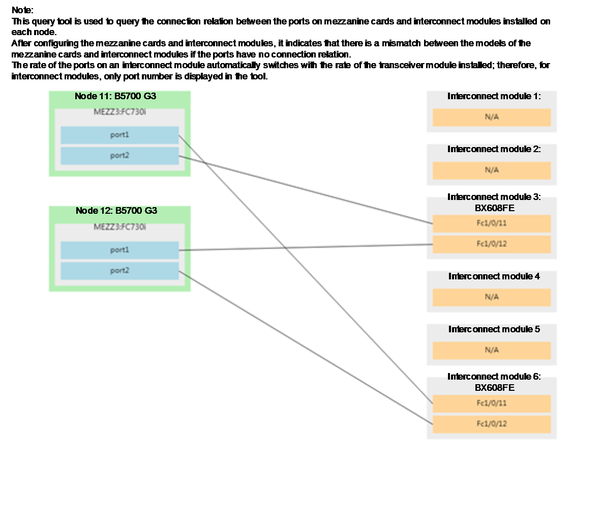
Querying the port connection relation between mezzanine cards and interconnect modules
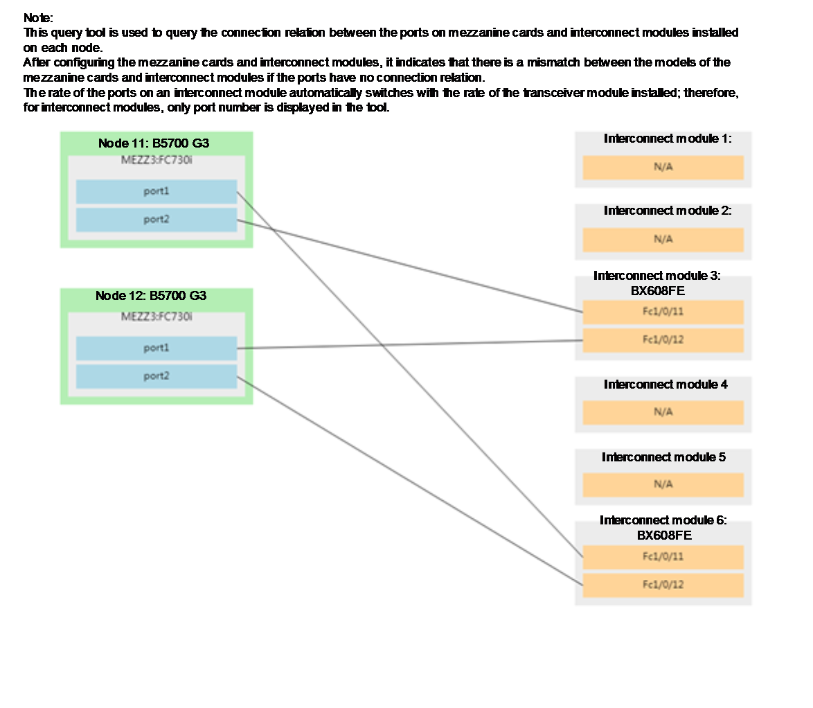
Please use the H3C networking query tool on the official website to view the port connection relation between mezzanine cards and interconnect modules.
As shown in Figure 7, according to the query result, the mezzanine card of the blade server 11 is connected to FC 1/0/11 ports of interconnect modules 3 and 6, and the mezzanine card of blade server 12 is connected to FC 1/0/12 ports of interconnect modules 3 and 6.
Figure 7 Port connection relation between mezzanine cards and interconnect modules
Configuring the mezzanine card
In the FC networking, the FC mezzanine card can be used correctly after being installed in place. There are no other special requirements in this example, so you do not need to configure the mezzanine card.
Configuring the interconnect module
Configuring the interconnect module 3
|
|
IMPORTANT: The internal port of the BX608FE interconnect module is in the shutdown state by default. Therefore, when configuring the module for the first time or restoring the default configuration file, execute the undo shutdown command to enable the corresponding port before configuring. Determine the internal port to which the mezzanine card port is connected according to "Querying port relations." |
# Configure the FCoE mode of the FC switch module to NPV.
<H3C> system-view
[H3C] fcoe-mode npv
# Create the VSAN. In this example, create VSAN 1.
[H3C] vsan 1
[H3C-vsan1] quit
# Create the VLAN to map VSAN. In this example, create VLAN 10, enable the FCoE function on VLAN 10, and map the VLAN to VSAN 1.
[H3C] vlan 10
[H3C-vlan10] fcoe enable vsan 1
[H3C-vlan10] quit
# Configure the mode of FC 1/1/1 and FC 1/1/2 ports connected to Brocade switches to NP, and add them to VSAN 1 using access.
[H3C] interface fc1/1/1
[H3C-Fc1/1/1] fc mode np
[H3C-Fc1/1/1] port access vsan 1
[H3C-Fc1/1/1] quit
[H3C] interface fc1/1/1
[H3C-Fc1/1/1] fc mode np
[H3C-Fc1/1/1] port access vsan 1
[H3C-Fc1/1/1] quit
# Configure the mode of FC 1/0/11 and FC 1/0/12 ports connected to mezzanine cards to F, and add them to VSAN 1 using access.
[H3C] interface fc1/1/1
[H3C-Fc1/0/11] fc mode f
[H3C-Fc1/1/1] port access vsan 1
[H3C-Fc1/1/1] quit
[H3C] interface fc1/1/1
[H3C-Fc1/0/11] fc mode f
[H3C-Fc1/1/1] port access vsan 1
[H3C-Fc1/1/1] quit
# Enter the VSAN view and initiate a manual load balancing.
[H3C] vsan 1
[H3C-vsan1] npv load-balance disruptive
The command may cause traffic interruption. Continue? [Y/N]:y
[H3C-vsan1] quit
|
|
CAUTION: If you want to restore load balancing after the uplink port gets down/up, you need to initiate a manual load balancing. Conduct link initialization on some downlink ports again. This operation will cause traffic interruption and affect the use of services. Please use it with caution. |
# Save the configuration.
[H3C] save
The current configuration will be written to the device. Are you sure? [Y/N]:y
Please input the file name(*.cfg)[flash:/startup.cfg]
(To leave the existing filename unchanged, press the enter key):
Configuring the interconnect module 6
|
|
IMPORTANT: The internal port of the BX608FE interconnect module is in the shutdown state by default. Therefore, when configuring the module for the first time or restoring the default configuration file, execute the undo shutdown command to enable the corresponding port before configuring. Determine the internal port to which the mezzanine card port is connected according to "Querying port relations." |
# Configure the FCoE mode of the FC switch module to NPV.
<H3C> system-view
[H3C] fcoe-mode npv
# Create the VSAN. In this example, create VSAN 2.
[H3C] vsan 2
[H3C-vsan2] quit
# Create the VLAN to map VSAN. In this example, create VLAN 20, enable the FCoE function on VLAN 20, and map the VLAN to VSAN 2.
[H3C] vlan 20
[H3C-vlan20] fcoe enable vsan 2
[H3C-vlan20] quit
# Configure the mode of FC 1/1/1 and FC 1/1/2 ports connected to Brocade switches to NP, and add them to VSAN 2 using access.
[H3C] interface fc1/1/1
[H3C-Fc1/1/1] fc mode np
[H3C-Fc1/1/1] port access vsan 1
[H3C-Fc1/1/1] quit
[H3C] interface fc1/1/1
[H3C-Fc1/1/1] fc mode np
[H3C-Fc1/1/1] port access vsan 1
[H3C-Fc1/1/1] quit
# Configure the mode of FC 2/0/11 and FC 1/0/12 ports connected to mezzanine cards to F, and add them to VSAN 1 using access.
[H3C] interface fc1/1/1
[H3C-Fc1/1/1] port access vsan 1
[H3C-Fc1/1/1] quit
[H3C] interface fc1/1/1
[H3C-Fc1/1/1] port access vsan 1
[H3C-Fc1/1/1] quit
# Enter the VSAN view and initiate a manual load balancing.
[H3C] vsan 2
[H3C-vsan1] npv load-balance disruptive
The command may cause traffic interruption. Continue? [Y/N]:y
[H3C-vsan1] quit
# Save the configuration.
[H3C] save
The current configuration will be written to the device. Are you sure? [Y/N]:y
Please input the file name(*.cfg)[flash:/startup.cfg]
(To leave the existing filename unchanged, press the enter key):
Querying the WWN number of the mezzanine card
Execute the display npv login command on the FC switch module to view the registration information about the node device (mezzanine card) connected to the downlink port of the FC switch module and the mapped uplink port. Here we use viewing the FC switch module 3 as an example:
<H3C>display npv login
Server External
Interface VSAN FCID Node WWN Port WWN Interface
Fc1/0/12 1 0x020101 20:00:f4:e9:D4:53:f1:c5 21:00:f4:e9:D4:53:f1:c4 Fc1/1/1
Fc1/0/11 1 0xc60004 20:00:00:10:9b:90:b2:99 10:00:00:10:9b:90:b2:99 Fc1/1/2
Configuring the Brocade switch
In this example, make sure that the two Brocade switches have different domain IDs, and Port 0, Port 1 and Port 2 of each switch reside in the same FC zone. For specific configuration methods, see relevant configuration manuals of Brocade switches.
Configuring 3Par storage
See "Configuring 3Par storage" for the process of configuring 3Par storage.
Configuring the OS
|
|
IMPORTANT: · The following information provides the procedure for configuring multipath under Red Hat 7.5. Multipath can realize the loading balancing and reliability of the traffic between hosts and storage devices. For the procedure for configuring multipath and verifying the configuration under Windows, see "Configuring multipath and adding network disks on Windows Server." · Before configuration, ensure that the OS has installed the multipath tool, a built-in tool of most Linux systems. |
Preparation
Execute the fdisk -l command under the OS to view the two virtual volumes identified by the host, as shown in Figure 8.
Figure 8 Identifying the virtual volumes

|
|
NOTE: If no disk is found, execute the echo 1 > /sys/class/fc_host/hostnum/issue_lip command to manually refresh fc_host, where hostnum indicates the host number under the /sys/class/fc_host directory, such as host 1. |
Configuring multipath
1. Execute the following commands in turn to load the multipath server, set the polling mode, enable the multipath service, and format the path.
# modprobe dm-multipath
# modprobe dm-round-robin
# systemctl start multipathd.service
# multipath -v2
|
|
NOTE: If it is prompted that the multipath.conf file does not exist under the Red Hat operating system, you can copy the file from another location and deliver it again, as shown in Figure 9. |
Figure 9 Handling the case when the multipath.conf file does not exist

2. Execute the following command to reboot the multipath server.
# systemctl restart multipathd.service
3. Run the following command to view the multipath link status, and you can see that the two ports are in the active state, as shown in Figure 10.
# multipath –ll
Figure 10 Viewing the multipath link status

Verifying the configuration
Verifying load balancing of ports on FC switch modules
Before and after load balancing, the mapping relation between the downlink ports (connected to the ports of mezzanine cards on blade servers) and the uplink ports (connected to the ports of FC switches) on the FC switch modules changes. Here we use the FC switch module 3 as an example.
1. Before load balancing, execute the display npv login command on the FC switch module. You can see the mapping relation between the uplink and downlink ports of the FC switch module, as follows:
<H3C>display npv login
Server External
Interface VSAN FCID Node WWN Port WWN Interface
Fc1/0/12 1 0x020101 20:00:f4:e9:D4:53:f1:c5 21:00:f4:e9:D4:53:f1:c4 Fc1/1/1
Fc1/0/11 1 0xc60004 20:00:00:10:9b:90:b2:99 10:00:00:10:9b:90:b2:99 Fc1/1/1
2. After load balancing, execute the display npv login command on the FC switch module again. You can see the changed mapping relation between the uplink and downlink ports of the FC switch module, as follows:
<H3C>display npv login
Server External
Interface VSAN FCID Node WWN Port WWN Interface
Fc1/0/12 1 0x020101 20:00:f4:e9:D4:53:f1:c5 21:00:f4:e9:D4:53:f1:c4 Fc1/1/1
Fc1/0/11 1 0xc60004 20:00:00:10:9b:90:b2:99 10:00:00:10:9b:90:b2:99 Fc1/1/2
Identifying storage volumes
As shown in Figure 11, execute the fdisk -l command under the OS to view the two virtual volumes identified by the host.
Figure 11 Identifying the virtual volumes
Accessing virtual volumes by the system through multiple paths
After multiple paths are configured, execute the fdisk -l command again to view the new mpatha volume, indicating that the system can access virtual volumes through multiple paths, as shown in Figure 12.
Figure 12 Viewing the mpatha volume

Example: Configuring FC (uplinking the aggregation interfaces of FC switch modules to FC switches)
Network requirement
As shown in Figure 13, two blade servers and two FC switch modules are installed in the H3C B16000 blade server chassis.
· The two blade servers are installed in slot 11 and slot 12, respectively.
· The two FC switch modules are installed in slot 3 and slot 6, respectively.
· An FC mezzanine card is installed in the mezzanine card slot 3 of the blade server.
· The FC 1/1/1 and FC 1/1/2 ports of the two FC switch modules are directly connected to the FC 1/1/1 and FC 1/1/2 ports of the two FC switches.
· The FC 1/1/3 ports of the two FC switches are directly connected to the 0:0:1 and 1:0:1 ports of the FC storage device.
In this example, the following devices and modules are used: blade server (H3C UniServer B5700 G3), mezzanine card (NIC-FC730i-Mb-2*32G, "FC730i"), FC switch module (BX608FE), FC switch (H3C S6800), and FC storage device (H3C CF8840 from the HPE 3Par StoreServ family).
The following requirements are expected to be met:
· Mounts storage volumes on the 3Par storage to the blade server to realize remote storage.
· Breaks through the single-port traffic bottleneck of FC switch modules.
· Ensures network reliability so the service is not affected when any FC switch or FC switch module fails.
Figure 13 Network diagram of uplinking multiple ports of FC switch modules in FCF mode to SAN
Analysis
· To mount 3Par storage volumes to the blade server, you need to build an FC link between the blade server and the 3Par storage to enable the transmission of FC traffic, which requires the following settings:
¡ Configure FC-related settings on the blade server and mezzanine card.
¡ Configure the FC function on the FC switch module.
¡ Configure the FC function on the FC switch to ensure FC link connectivity.
¡ Create a storage volume on the 3Par so that the blade server's OS can automatically recognize the storage volume.
· To break through the single-port traffic bottleneck of FC switch modules, you need to aggregate multiple physical ports of FC switch modules to form an FC aggregation interface, to realize bandwidth aggregation and load sharing. You need to aggregate multiple ports in the FCF mode. Therefore, you need to configure the ports of the FC switch module to operate in the FCF mode.
· As a best practice, connect each interconnect module to an FC switch for link redundancy, thus avoiding network disconnection caused by FC switch failure.
· To ensure service continuity when any FC interconnect module fails, you need to configure the multipath function under the OS of the blade server to improve network reliability.
Software versions used
This example was configured and verified on the SWITCH_SYS-1.02.04 version of the FC interconnect module.
Configuration precautions
· Before adding a storage volume, ensure that the blade server has installed the OS and the appropriate network adapter driver, so that the OS can identify the FC730i network adapter correctly. For details about installing the OS, see H3C Servers Operating System Installation Guide. For details about installing the network adapter driver, see FC730i Mezzanine Card Module User Guide.
· After mounting the storage volumes and replacing existing storage volumes on the 3Par with new ones, reboot the OS of the blade server to identify the new volumes.
Configuration procedure
Query the port connection between mezzanine cards and interconnect modules
Please use the H3C networking query tool on the official website to view the port connection relation between mezzanine cards and interconnect modules.
As shown in Figure 14, according to the query result, the mezzanine card of the blade server 11 is connected to FC 1/0/11 ports of interconnect modules 3 and 6, and the mezzanine card of blade server 12 is connected to FC 1/0/12 ports of interconnect modules 3 and 6.
Figure 14 Port connection relation between mezzanine cards and interconnect modules
Configuring the mezzanine card
In the FC networking, the FC mezzanine card can be used correctly after being installed in place. There are no other special requirements in this example, so you do not need to configure the mezzanine card.
Configuring the interconnect module
Configuring interconnect module 3
|
|
IMPORTANT: The internal port of the BX608FE interconnect module is in the shutdown state by default. Therefore, when configuring the module for the first time or restoring the default configuration file, execute the undo shutdown command to enable the corresponding port before configuring. Determine the internal port to which the mezzanine card port is connected according to "Querying port relations." |
# Configure the mode of the FC switch module to FCF.
<H3C> system-view
[H3C] fcoe-mode fcf
# Create the VSAN. In this example, create VSAN 1 and allow members in the default zone to access each other.
[H3C] vsan 1
[H3C-vsan1] zone default-zone permit
[H3C-vsan1] quit
# Create the VLAN to map VSAN. In this example, create VLAN 10, enable the FCoE function on VLAN 10, and map the VLAN to VSAN 1.
[H3C] vlan 10
[H3C-vlan10] fcoe enable vsan 1
[H3C-vlan10] quit
# Add FC 1/0/11 and FC 1/0/12 ports to VSAN 1 and set them to operate in the F mode.
[H3C] interface fc1/1/1
[H3C-Fc1/0/11] fc mode f
[H3C-Fc1/1/1] port access vsan 1
[H3C-Fc1/1/1] quit
[H3C] interface fc1/1/1
[H3C-Fc1/0/12] fc mode f
[H3C-Fc1/1/1] port access vsan 1
[H3C-Fc1/1/1] quit
# Create FC aggregation interface 1 and generate FC aggregation group 1.
[H3C] interface san-aggregation 1
# Configure FC aggregation interface 1 to operate in the E mode.
[H3C-SAN-Aggregation1] fc mode e
# Add FC aggregation interface 1 to VSAN 1 through the access mode, set the trunk mode of FC aggregation interface 1 to On, and add the port to the VSAN 1 through the trunk mode, that is, permit the VSAN 1 packets to pass.
[H3C-SAN-Aggregation1] port access vsan 1
[H3C-SAN-Aggregation1] port trunk mode on
[H3C-SAN-Aggregation1] port trunk vsan 1
[H3C-SAN-Aggregation1] quit
# Add the FC 1/1/1 and FC 1/1/2 ports to FC aggregation group 1.
[H3C] interface fc 1/1/1
[H3C-Fc1/1/1] shutdown
[H3C-Fc1/1/1] san-aggregation group 1
The FC mode, trunk mode, trunk VSAN, and access VSAN settings of the FC interface will be lost. Continue? [Y/N]:y
[H3C-Fc1/1/1] undo shutdown
[H3C-Fc1/1/1] quit
[H3C] interface fc 1/1/2
[H3C-Fc1/1/2] shutdown
[H3C-Fc1/1/2] san-aggregation group 1
The FC mode, trunk mode, trunk VSAN, and access VSAN settings of the FC interface will be lost. Continue? [Y/N]:y
[H3C-Fc1/1/2] undo shutdown
[H3C-Fc1/1/1] quit
# Save the configuration.
[H3C] save
The current configuration will be written to the device. Are you sure? [Y/N]:y
Please input the file name(*.cfg)[flash:/startup.cfg]
(To leave the existing filename unchanged, press the enter key):
Configuring interconnect module 6
|
|
IMPORTANT: The internal port of the BX608FE interconnect module is in the shutdown state by default. Therefore, when configuring the module for the first time or restoring the default configuration file, execute the undo shutdown command to enable the corresponding port before configuring. Determine the internal port to which the mezzanine card port is connected according to "Querying port relations." |
# Configure the mode of the FC switch module to FCF.
<H3C> system-view
[H3C] fcoe-mode fcf
# Create the VSAN. In this example, create VSAN 2 and allow members in the default zone to access each other.
[H3C] vsan 2
[H3C-vsan2] zone default-zone permit
[H3C-vsan2] quit
# Create the VLAN to map VSAN. In this example, create VLAN 20, enable the FCoE function on VLAN 20, and map the VLAN to VSAN 2.
[H3C] vlan 20
[H3C-vlan20] fcoe enable vsan 2
[H3C-vlan20] quit
# Add FC 1/0/11 and FC 1/0/12 ports to VSAN 2 and set to the F mode.
[H3C] interface fc1/1/1
[H3C-Fc1/0/11] fc mode f
[H3C-Fc1/1/1] port access vsan 1
[H3C-Fc1/1/1] quit
[H3C] interface fc1/1/1
[H3C-Fc1/0/12] fc mode f
[H3C-Fc1/1/1] port access vsan 1
[H3C-Fc1/1/1] quit
# Create FC aggregation interface 1 and generate FC aggregation group 1.
[H3C] interface san-aggregation 1
# Configure FC aggregation interface 1 to operate in the E mode.
[H3C-SAN-Aggregation1] fc mode e
# Add FC aggregation interface 1 to VSAN 1 through the access mode, set the trunk mode of FC aggregation interface 1 to On, and add the port to the VSAN 2 through the trunk mode, that is, permit the VSAN 1 packets to pass.
[H3C-SAN-Aggregation1] port access vsan 2
[H3C-SAN-Aggregation1] port trunk mode on
[H3C-SAN-Aggregation1] port trunk vsan 2
[H3C-SAN-Aggregation1] quit
# Add the FC 1/1/1 and FC 1/1/2 ports to FC aggregation group 1.
[H3C] interface fc 1/1/1
[H3C-Fc1/1/1] shutdown
[H3C-Fc1/1/1] san-aggregation group 1
The FC mode, trunk mode, trunk VSAN, and access VSAN settings of the FC interface will be lost. Continue? [Y/N]:y
[H3C-Fc1/1/1] undo shutdown
[H3C-Fc1/1/1] quit
[H3C] interface fc 1/1/2
[H3C-Fc1/1/2] shutdown
[H3C-Fc1/1/2] san-aggregation group 1
The FC mode, trunk mode, trunk VSAN, and access VSAN settings of the FC interface will be lost. Continue? [Y/N]:y
[H3C-Fc1/1/2] undo shutdown
[H3C-Fc1/1/1] quit
# Save the configuration.
[H3C] save
The current configuration will be written to the device. Are you sure? [Y/N]:y
Please input the file name(*.cfg)[flash:/startup.cfg]
(To leave the existing filename unchanged, press the enter key):
Configuring an FC switch
Configuring uplink SAN switch A
# Configure the FC switch to operate in the FCF mode.
<H3C> system-view
[H3C] fcoe-mode fcf
# Create the VSAN. In this example, create VSAN 1 and allow members in the default zone to access each other.
[H3C] vsan 1
[H3C-vsan1] zone default-zone permit
[H3C-vsan1] quit
# Create the VLAN to map VSAN. In this example, create VLAN 10, enable the FCoE function on VLAN 10, and map the VLAN to VSAN 1.
[H3C] vlan 10
[H3C-vlan10] fcoe enable vsan 1
[H3C-vlan10] quit
# Create FC aggregation interface 1 and generate FC aggregation group 1.
[H3C] interface san-aggregation 1
# Configure FC aggregation interface 1 to operate in the E mode.
[H3C -SAN-Aggregation1] fc mode e
# Add FC aggregation interface 1 to VSAN 1 through the access mode, set the trunk mode of FC aggregation interface 1 to On, and add the port to the VSAN 10 through the trunk mode, that is, permit the VSAN 10 packets to pass.
[H3C-SAN-Aggregation1] port access vsan 1
[H3C-SAN-Aggregation1] port trunk mode on
[H3C-SAN-Aggregation1] port trunk vsan 1
[H3C-SAN-Aggregation1] quit
# Add the FC 1/1/1 and FC 1/1/2 ports to FC aggregation group 1.
[H3C] interface fc 1/1/1
[H3C-Fc1/1/1] shutdown
[H3C-Fc1/1/1] san-aggregation group 1
The FC mode, trunk mode, trunk VSAN, and access VSAN settings of the FC interface will be lost. Continue? [Y/N]:y
[H3C-Fc1/1/1] undo shutdown
[H3C-Fc1/1/1] quit
[H3C] interface fc 1/1/2
[H3C-Fc1/1/2] shutdown
[H3C-Fc1/1/2] san-aggregation group 1
The FC mode, trunk mode, trunk VSAN, and access VSAN settings of the FC interface will be lost. Continue? [Y/N]:y
[H3C-Fc1/1/2] undo shutdown
[H3C-Fc1/1/1] quit
# Set the FC 1/1/3 port connected to the 3Par storage to operate in the F mode.
[H3C] interface fc1/1/1
[H3C-Fc1/1/3] fc mode f
[H3C-Fc1/1/1] quit
# Save the configuration.
[H3C] save
The current configuration will be written to the device. Are you sure? [Y/N]:y
Please input the file name(*.cfg)[flash:/startup.cfg]
(To leave the existing filename unchanged, press the enter key):
Configuring uplink SAN switch B
# Configure the FC switch to operate in the FCF mode.
<H3C> system-view
[H3C] fcoe-mode fcf
# Create the VSAN. In this example, create VSAN 2 and allow members in the default zone to access each other.
[H3C] vsan 2
[H3C-vsan2] zone default-zone permit
[H3C-vsan2] quit
# Create the VLAN to map VSAN. In this example, create VLAN 20, enable the FCoE function on VLAN 20, and map the VLAN to VSAN 2.
[H3C] vlan 20
[H3C-vlan20] fcoe enable vsan 2
[H3C-vlan20] quit
# Create FC aggregation interface 1 and generate FC aggregation group 1.
[H3C] interface san-aggregation 1
# Configure FC aggregation interface 1 to operate in the E mode.
[H3C -SAN-Aggregation1] fc mode e
# Add FC aggregation interface 1 to VSAN 1 through the access mode, set the trunk mode of FC aggregation interface 1 to On, and add the port to the VSAN 10 through the trunk mode, that is, permit the VSAN 10 packets to pass.
[H3C-SAN-Aggregation1] port access vsan 2
[H3C-SAN-Aggregation1] port trunk mode on
[H3C-SAN-Aggregation1] port trunk vsan 2
[H3C-SAN-Aggregation1] quit
# Add the FC 1/1/1 and FC 1/1/2 ports to FC aggregation group 1.
[H3C] interface fc 1/1/1
[H3C-Fc1/1/1] shutdown
[H3C-Fc1/1/1] san-aggregation group 1
The FC mode, trunk mode, trunk VSAN, and access VSAN settings of the FC interface will be lost. Continue? [Y/N]:y
[H3C-Fc1/1/1] undo shutdown
[H3C-Fc1/1/1] quit
[H3C] interface fc 1/1/2
[H3C-Fc1/1/2] shutdown
[H3C-Fc1/1/2] san-aggregation group 1
The FC mode, trunk mode, trunk VSAN, and access VSAN settings of the FC interface will be lost. Continue? [Y/N]:y
[H3C-Fc1/1/2] undo shutdown
[H3C-Fc1/1/1] quit
# Add the FC 1/1/3 port connected to the 3Par storage to VSAN 2 and configure it to operate in the F mode.
[H3C] interface fc1/1/1
[H3C-Fc1/1/3] fc mode f
[H3C-Fc1/1/3] port access vsan 2
[H3C-Fc1/1/1] quit
# Save the configuration.
[H3C] save
The current configuration will be written to the device. Are you sure? [Y/N]:y
Please input the file name(*.cfg)[flash:/startup.cfg]
(To leave the existing filename unchanged, press the enter key):
Querying the WWN of the node connected to the FC switch module
Execute the display fc login command on the FC switch module to view information about the node connected to the module. Here we use viewing the FC switch module 3 as an example:
<H3C> display fc login
Interface VSAN FCID Node WWN Port WWN
Fc1/0/11 1 0x760000 20:00:f4:e9:d4:53:f1:c5 21:00:f4:e9:d4:53:f1:c5
Fc1/0/12 1 0x760001 20:00:f4:e9:d4:58:6a:06 21:00:f4:e9:d4:58:6a:06
Table 3 Description of the information displayed by executing the display fc login command
|
Field |
Description |
|
Interface |
The port through which the switch and the node are connected |
|
VSAN |
VSAN ID |
|
FCID |
The FC address of the node assigned by the switch |
|
Node WWN |
The WWN of the node |
|
Port WWN |
The WWN of the port through which the node and the switch are connected |
Configuring 3Par storage
See "Configuring 3Par storage" for the process of configuring 3Par storage.
Configuring the OS
|
|
IMPORTANT: · The following information provides the procedure for configuring multipath under Red Hat 7.5. Multipath can realize the loading balancing and reliability of the traffic between hosts and storage devices. For the procedure for configuring multipath and verifying the configuration under Windows, see "Configuring multipath and adding network disks on Windows Server." · Before configuration, ensure that the OS has installed the multipath tool, a built-in tool of most Linux systems. |
Preparation
Execute the fdisk -l command under the OS to view the two virtual volumes identified by the host, as shown in Figure 15.
Figure 15 Identifying the virtual volumes

|
|
NOTE: If no disk is found, execute the echo 1 > /sys/class/fc_host/hostnum/issue_lip command to manually refresh fc_host, where hostnum indicates the host number under the /sys/class/fc_host directory, such as host 1. |
Configuring multipath
1. Execute the following commands in turn to load the multipath server, set the polling mode, enable the multipath service, and format the path.
# modprobe dm-multipath
# modprobe dm-round-robin
# systemctl start multipathd.service
# multipath -v2
|
|
NOTE: If it is prompted that the multipath.conf file does not exist under the Red Hat operating system, you can copy the file from another location and deliver it again, as shown in Figure 16. |
Figure 16 Handling the case when the multipath.conf file does not exist

2. Execute the following command to reboot the multipath server.
# systemctl restart multipathd.service
3. Run the following command to view the multipath link status, and you can see that the two ports are in the active state, as shown in Figure 17.
# multipath –ll
Figure 17 Viewing the multipath link status

Verifying the configuration
Identifying storage volumes
As shown in Figure 18, execute the fdisk -l command under the OS to view the two virtual volumes identified by the host, indicating that the server-to-storage FC link is connected and the storage volumes are mounted.
Figure 18 Identifying the virtual volumes

Verifying the configuration of the FC aggregation group
Before and after FC aggregation, the mapping relation between the downlink ports (connected to the ports of mezzanine cards on blade servers) and the uplink ports (connected to the ports of FC switches) on the FC switch modules changes. Here we use the FC switch module 3 as an example.
# Display the brief information about FC aggregation group 1 on the FC switch module.
[H3C] display san-aggregation interface san-aggregation 1
* indicates the member port is selected.
Interface State Mode Speed Member port
SAGG1 UP E 16Gbps *Fc1/1/1
*Fc1/1/2
# Display the details of FC aggregation group 1 on the FC switch module.
[H3C] display san-aggregation verbose interface san-aggregation 1
Interface SAN-Aggregation1:
State : UP
Mode : E
Speed : 32Gbps
Member port number : 2
Selected port number : 2
Member port State Mode Speed Selected
Fc1/1/1 UP E 16Gbps Y
Fc1/1/2 UP E 16Gbps Y
The above information indicates that both the FC 1/1/1 and FC 1/1/2 ports are selected for sharing traffic load. The FC aggregation interface has a speed of 32 Gbps that is the sum of the speeds of two FC ports. When one FC port fails, the other FC port can transmit the traffic, thus improving the reliability of link connection.
Accessing virtual volumes by the system through multiple paths
After multiple paths are configured, execute the fdisk -l command again to view the new mpatha volume, indicating that the system can access virtual volumes through multiple paths, as shown in Figure 19. This ensures service continuity when any FC switch or FC switch module fails.
Figure 19 Viewing the mpatha volume

Example: Configuring FC (directly connecting FC switch modules to the 3Par storage)
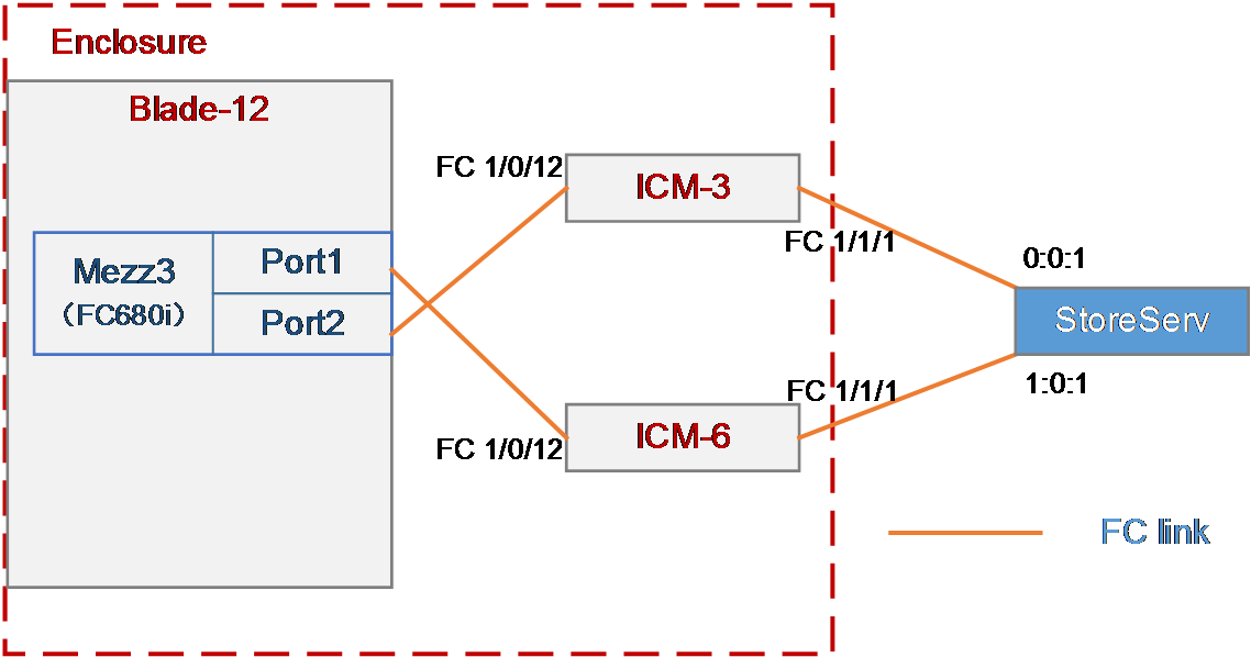
Network requirement
As shown in Figure 20, a blade server and two FC switch modules are installed in the H3C B16000 blade server chassis. The blade server is installed in slot 12, the two FC switch modules are installed in slot 3 and slot 6, and the mezzanine card is installed in the mezzanine card slot 3 of the blade server. The FC 1/1/1 port of each of the two FC switch modules is directly connected to the 0:0:1 or 1:0:1 port of the 3Par storage.
In this example, the following devices and modules are used: blade server (H3C UniServer B5700 G3), mezzanine card (NIC-FC680i-Mb-2*16G, "FC680i"), FC switch module (BX608FE), and FC storage device (H3C CF8840 from the HPE 3Par StoreServ family).
The following requirements are expected to be met:
The OS on the blade server can mount storage volumes on the 3Par to realize remote storage, and data on the 3Par can be accessed through the OS when any interconnect module fails.
Figure 20 Network diagram between FC switch modules (FCF mode) and the FC storage device
Analysis
· To mount a 3Par storage volume under the OS, build an FC link between the blade server and the 3Par storage, and create a storage volume on the 3Par storage. Then, the OS can automatically identify the storage volume.
· In this example, the FC switch modules are directly connected to the FC storage device. You need to configure the mode of the two FC switch modules to FCF.
· To ensure service continuity when any interconnect module fails, you need to configure the multipath function under the OS to improve network reliability.
· As a best practice, connect two interconnect modules to two different FC switches respectively for link redundancy, thus avoiding network disconnection caused by FC switch failure.
Software versions used
This example was created and verified on versions SWITCH_SYS-1.00.11 and OM-1.00.11 of interconnect modules.
Configuration precautions
· Before adding a storage volume, ensure that the blade server has installed the OS and the appropriate network adapter driver, so that the OS can identify the FC680i network adapter correctly. For details about installing the OS, see H3C Servers Operating System Installation Guide. For details about installing the network adapter driver, see FC680i Mezzanine Card Module User Guide.
· After mounting the storage volumes and replacing existing storage volumes on the 3Par with new ones, reboot the OS of the blade server to identify the new volumes.
Configuration procedure
Querying port information
Query the connection relation between the internal ports of mezzanine cards and interconnect modules according to "Querying port relations."
It can be seen that the FC 1/0/12 ports of the interconnect module 3 and interconnect module 6 are used in this example.
Configuring the mezzanine card
In the FC networking, the FC mezzanine card can be used correctly after being installed in place. There are no other special requirements in this example, so you do not need to configure the mezzanine card.
Configuring the interconnect module
Configuring interconnect module 3
|
|
NOTE: The internal port of the BX608FE interconnect module is in the shutdown state by default. Therefore, when configuring the module for the first time or restoring the default configuration file, execute the undo shutdown command to enable the corresponding port before configuring. Determine the internal port to which the mezzanine card port is connected according to "Querying port relations." |
# Configure the FCoE mode of the switch to FCF.
<H3C> system-view
[H3C] fcoe-mode fcf
# Create the VSAN. In this example, create VSAN 1 and allow members in the default zone to access each other.
[H3C] vsan 1
[H3C-vsan1] zone default-zone permit
[H3C-vsan1] quit
# Create the VLAN to map VSAN. In this example, create VLAN 10, enable the FCoE function on VLAN 10, and map the VLAN to VSAN 1.
[H3C] vlan 10
[H3C-vlan10] fcoe enable vsan 1
[H3C-vlan10] quit
# Configure the port connected to the 3Par storage server to operate in the F mode.
[H3C] interface fc1/1/1
[H3C-Fc1/1/1] fc mode f
[H3C-Fc1/1/1] quit
# Save the configuration.
[H3C] save
The current configuration will be written to the device. Are you sure? [Y/N]:y
Please input the file name(*.cfg)[flash:/startup.cfg]
(To leave the existing filename unchanged, press the enter key):
Configuring interconnect module 6
|
|
NOTE: The internal port of the BX608FE interconnect module is in the shutdown state by default. Therefore, when configuring the module for the first time or restoring the default configuration file, execute the undo shutdown command to enable the corresponding port before configuring. Determine the internal port to which the mezzanine card port is connected according to. |
# Configure the FCoE mode of the switch to FCF.
<H3C> system-view
[H3C] fcoe-mode fcf
# Create the VSAN. In this example, create VSAN 2 and allow members in the default zone to access each other.
[H3C] vsan 2
[H3C-vsan2] zone default-zone permit
[H3C-vsan2] quit
# Create the VLAN to map VSAN. In this example, create VLAN 20, enable the FCoE function on VLAN 20, and map the VLAN to VSAN 2.
[H3C] vlan 20
[H3C-vlan20] fcoe enable vsan 2
[H3C-vlan20] quit
# Configure the port connected to the 3Par storage server to operate in the F mode.
[H3C] interface fc1/1/1
[H3C-Fc1/1/1] fc mode f
[H3C-Fc1/1/1] port access vsan 2
[H3C-Fc1/1/1] quit
# Add the internal port to VSAN 2.
[H3C] interface fc1/1/1
[H3C-Fc1/0/12] port access vsan 2
[H3C-Fc1/1/1] quit
# Save the configuration.
[H3C] save
The current configuration will be written to the device. Are you sure? [Y/N]:y
Please input the file name(*.cfg)[flash:/startup.cfg]
(To leave the existing filename unchanged, press the enter key):
Querying the WWN of the node connected to the FC switch module
Execute the display fc login command on the FC switch module to view information about the node connected to the module. Here we use viewing the FC switch module 3 as an example:
<H3C> display fc login
Interface VSAN FCID Node WWN Port WWN
Fc1/0/12 1 0x760000 20:00:f4:e9:d4:53:f1:c5 21:00:f4:e9:d4:53:f1:c5
Fc1/1/1 1 0x760001 2f:f7:00:02:ac:02:28:66 21:01:00:02:ac:02:28:66
Table 4 Description of the information displayed by executing the display fc login command
|
Field |
Description |
|
Interface |
The port through which the switch and the node are connected |
|
VSAN |
VSAN ID |
|
FCID |
The FC address of the node assigned by the switch |
|
Node WWN |
The WWN of the node |
|
Port WWN |
The WWN of the port through which the node and the switch are connected |
Configuring 3Par storage
See "Configuring 3Par storage" for the process of configuring the 3Par storage server.
Configuring the OS
|
|
NOTE: · The following information provides the procedure for configuring multipath under Red Hat 7.5. Multipath can realize the loading balancing and reliability of the traffic between hosts and storage devices. For the procedure for configuring multipath and verifying the configuration under Windows, see "Configuring multipath and adding network disks on Windows Server." · Before configuration, ensure that the OS has installed the multipath tool, a built-in tool of most Linux systems. |
Preparation
Execute the fdisk -l command under the OS to view the two virtual volumes identified by the host, as shown in Figure 21.
Figure 21 Identifying the virtual volumes

|
|
NOTE: If no disk is found, execute the echo 1 > /sys/class/fc_host/hostnum/issue_lip command to manually refresh fc_host, where hostnum indicates the host number under the /sys/class/fc_host directory, such as host 1. |
Configuring multipath
1. Execute the following commands in turn to load the multipath server, set the polling mode, enable the multipath service, and format the path.
# modprobe dm-multipath
# modprobe dm-round-robin
# service multipathd start
# multipath –v2
|
|
NOTE: If it is prompted that the multipath.conf file does not exist under the Red Hat operating system, you can copy the file from another location and deliver it again, as shown in Figure 22. |
Figure 22 Handling the case when the multipath.conf file does not exist

2. Execute the following command to reboot the multipath server.
# systemctl restart multipathd.service
Verifying the configuration
After configuring the multipath, execute the fdisk -l command again. You can see a new mpatha volume, indicating that the system can access virtual volumes through multiple paths, as shown in Figure 23.
Figure 23 Viewing the mpatha volume

Example: Configuring FCoE (connecting aggregation interconnect modules to FC switches)
Network requirement
As shown in Figure 24, a blade server and two aggregation interconnect modules are installed in the H3C B16000 blade server chassis. The blade server is installed in slot 12, two aggregation interconnect modules are installed in slot 1 and slot 4, and the mezzanine card is installed in the mezzanine card slot 1 of the blade server. The FC 1/1/1 port of each of the two aggregation interconnect modules is connected to the FC switch, and the FC switch is connected to the 0:0:1 port of the FC storage device.
In this example, the following devices and modules are used: blade server (H3C UniServer B5700 G3), mezzanine card (NIC-ETH521i-Mb-4*10G, "ETH521i"), aggregation interconnect module (BX720EF), FC switch (Brocade 6510), and FC storage device (H3C CF8840 from the HPE 3Par StoreServ family).
The following requirements are expected to be met:
The OS on the blade server can mount storage volumes on the 3Par to realize lossless remote storage, and you can still access data on the 3Par through the OS when any interconnect module fails.
Analysis
· To mount a 3Par storage volume under the OS, build an FC link between the blade server and the 3Par storage, and create a storage volume on the 3Par storage. Then, the OS can automatically identify the storage volume.
· In this example, aggregation interconnect modules are used, and the blade server and interconnect modules are connected through Ethernet links. Therefore, you need to configure the FCoE function on mezzanine cards and interconnect modules to transmit FC traffic.
· The first eight external ports on the BX720EF aggregation interconnect module support FC/Ethernet handoff and need to be switched to the FC mode.
· In this example, the aggregation interconnect modules are directly connected to FC switches. You need to configure the mode of the two interconnect modules to NPV.
· To ensure service continuity when any interconnect module fails, you need to configure the multipath function under the OS to improve network reliability.
· As a best practice, configure the PFC and ETS functions of DCBX and auto-negotiation modes on the internal ports of the interconnect modules, to transmit storage data traffic of a SAN network over Ethernet links without losses.
Software versions used
This example was created and verified on versions SWITCH_SYS-1.00.11 and OM-1.00.11 of interconnect modules.
Configuration precautions
· Before adding a storage volume, ensure that the blade server has installed the OS and the appropriate network adapter driver, so that the OS can identify the ETH521i network adapter correctly. For details about installing the OS, see H3C Servers Operating System Installation Guide. For details about installing the network adapter driver, see ETH521i Mezzanine Card Module User Guide.
· After mounting the storage volumes and replacing existing storage volumes on the 3Par with new ones, reboot the OS of the blade server to identify the new volumes.
· As a best practice, disable the STP function of the internal ports on the interconnect modules, to prevent the rebooting or plugging in/out of the blade server from causing the STP of the interconnect modules to start calculating and resulting in short disconnection of external ports on the interconnect modules.
· Some packets are transmitted through VLAN 1 during the negotiation of the FCoE protocol. To ensure correct protocol negotiation, do not modify the relevant default settings of VLAN 1 to ensure normal communication of VLAN 1 traffic between the interconnect modules and blade servers.
· If you configure both FC ports and VFC ports on your devices, execute the qos trust dot1p command to enable normal PFC of the VFC ports.
Configuration procedure
Querying port information
Query the correspondence among mezzanine cards, internal ports of interconnect modules, and network adapters under the OS according to "Querying port relations."
It can be learned that:
· In this example, Port 1 and Port 3 of mezzanine card 3 are used and are named ens5f0 and ens5f2 under the OS, respectively.
· Ten-gigabitethernet 1/0/23 ports of interconnect modules 1 and 4 are used in this example.
Configuring the mezzanine card
|
|
NOTE: · In this example, Red Hat 7.5 is installed on the blade server and used as an example in the following steps. · When Windows Server is installed on a blade server, there is no need to configure the mezzanine cards under the system. |
1. Configure the FCoE function of ens5f0 and ens5f2 ports:
a. Under the /etc/fcoe directory, execute the cp cfg-ethX cfg-ethM command to copy and create the FCoE port configuration file. Where, cfg-ethM indicates the port name for FCoE connection. In this example, the names are cfg-ens5f0 and cfg-ens5f2. The following contents use cfg-ens5f0 as an example to describe the configuration steps.
[root@localhost]# cd /etc/fcoe/
[root@localhost fcoe]# ls
cfg-ethx
[root@localhost fcoe]# cp cfg-ethx cfg-ens5f0
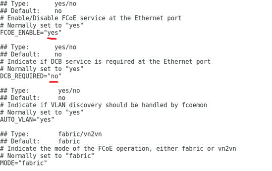
b. Execute the vi cfg-ethM command, edit and save the FCoE port configuration file, and ensure that FCOE_ENABLE = yes, and DCB_REQUIRED = no, as shown in Figure 25.
[root@localhost fcoe]# vi cfg-ens5f0
Figure 25 Editing the FCoE port configuration file
c. Execute the lldptool set-lldp -i ethM adminStatus=disabled command to set the LLDP admin status of the port to disabled. Then, check the configuration value of adminStatus of ethM in the /var/lib/lldpad/lldpad.conf configuration file. If it is zero, the command is executed successfully. If it is not, manually add a line "adminStatus = 0" to the "ethM" entry under "lldp" in the configuration file, as shown in Figure 26.
[root@localhost fcoe]# lldptool set-lldp –i ens5f0 adminStatus=disabled
Figure 26 Disabling the LLDP admin status

d. Execute the service fcoe restart and service lldpad restart commands to restart the FCoE and LLDP services.
[root@localhost fcoe]# service lldpad restart
[root@localhost fcoe]# service fcoe restart
e. Execute the chkconfig fcoe on and chkconfig lldpad on commands to automatically load the FCoE and LLDP services during the boot phase.
[root@localhost fcoe]# chkconfig fcoe on
[root@localhost fcoe]# chkconfig lldpad on
Configuring the interconnect module
Interconnecting interconnect modules and mezzanine cards
1. Configuring FCoE-related settings and ports
<H3C> system-view
# Configure the FCoE mode of the switch to NPV.
[H3C] fcoe-mode npv
# Create the VSAN on interconnect module 1. In this example, VSAN 1 is created.
[H3C] vsan 1
[H3C-vsan1] quit
# Create VLAN 10 on interconnect module 1 to map VSAN 1, and enable the FCoE function on VLAN 10.
[H3C] vlan 10
[H3C-vlan10] fcoe enable vsan 1
[H3C-vlan10] quit
# Create VFC ports on interconnect module 1, and bind them with internal ports XGE 1/0/23.
[H3C] interface vfc 1
[H3C-Vfc1] bind interface Ten-GigabitEthernet1/0/23
[H3C-Vfc1] port trunk vsan 1
[H3C-Vfc1] quit
# Configure the internal physical ports of interconnect module 1 to the trunk mode and allow VLAN 10 to pass.
[H3C] interface Ten-GigabitEthernet1/0/23
[H3C-Ten-GigabitEthernet1/0/23] port link-type trunk
[H3C-Ten-GigabitEthernet1/0/23] port trunk permit vlan 10
[H3C-Ten-GigabitEthernet1/0/23] undo stp enable
[H3C-Ten-GigabitEthernet1/0/23] quit
# Create the VSAN on interconnect module 4. In this example, VSAN 2 is created.
[H3C] vsan 2
[H3C-vsan2] quit
# Create VLAN 20 on interconnect module 4 to map VSAN 2 and enable the FCoE function on VLAN 20.
[H3C] vlan 20
[H3C-vlan20] fcoe enable vsan 2
[H3C-vlan20] quit
# Create VFC ports on interconnect module 4, and bind them with internal ports XGE 1/0/23.
[H3C] interface vfc 2
[H3C-Vfc2] bind interface Ten-GigabitEthernet1/0/23
[H3C-Vfc2] port trunk vsan 2
[H3C-Vfc2] quit
# Configure the internal physical ports of interconnect module 4 to the trunk mode and allow VLAN 20 to pass.
[H3C] interface Ten-GigabitEthernet1/0/23
[H3C-Ten-GigabitEthernet1/0/23] port link-type trunk
[H3C-Ten-GigabitEthernet1/0/23] port trunk permit vlan 20
[H3C-Ten-GigabitEthernet1/0/23] undo stp enable
[H3C-Ten-GigabitEthernet1/0/23] quit
2. Deploying DCBX
# Enable LLDP function globally.
[H3C] lldp global enable
# Create a Layer 2 ACL named DCBX and create rules for it to match FCoE packets (protocol number 0x8906) and FIP packets (protocol number 0x8914).
[H3C] acl mac name DCBX
[H3C-acl-mac-DCBX] rule 0 permit type 8906 ffff
[H3C-acl-mac-DCBX] rule 5 permit type 8914 ffff
[H3C-acl-mac-DCBX] quit
# Define a class named DCBX, the relation between the rules under it is OR, and define it to match the ACL named DCBX.
[H3C] traffic classifier DCBX operator or
[H3C-classifier-DCBX] if-match acl mac name DCBX
[H3C-classifier-DCBX] quit
# Define a stream behavior named DCBX and set the priority of the marked packets 802.1p to 3.
[H3C] traffic behavior DCBX
[H3C-behavior-DCBX] remark dot1p 3
[H3C-behavior-DCBX] quit
# Define a QoS policy named DCBX, specify the DCBX-like stream behavior as DCBX, and specify the policy as DCBX mode.
[H3C] qos policy DCBX
[H3C-qospolicy-DCBX] classifier DCBX behavior DCBX mode dcbx
[H3C-qospolicy-DCBX] quit
# Enable the LLDP function on the aggregation interface, and configure the bound physical ports to allow the port to send LLDP packets with DCBX TLV fields.
[H3C] interface Ten-GigabitEthernet 1/0/23
[H3C-Ten-GigabitEthernet1/0/23] lldp tlv-enable dot1-tlv dcbx
[H3C-Ten-GigabitEthernet1/0/23] qos apply policy DCBX outbound
[H3C-Ten-GigabitEthernet1/0/23] quit
3. Deploying PFC
|
|
NOTE: The WGE 1/1/1 to WGE 1/1/8 ports of the BX1020EF switch module does not support the PFC function. Therefore, do not use these ports to configure FCoE networking in actual situations. Otherwise, the network may not work correctly. |
# Configure the function to enable PFC through automatic negotiation with the server on the physical ports, enable the PFC function for 802.1p with priority set to 3, and configure to trust packets with the 802.1p priority.
[H3C] interface Ten-GigabitEthernet 1/0/23
[H3C-Ten-GigabitEthernet1/0/23] priority-flow-control auto
[H3C-Ten-GigabitEthernet1/0/23] priority-flow-control no-drop dot1p 3
[H3C-Ten-GigabitEthernet1/0/23] qos trust dot1p
[H3C-Ten-GigabitEthernet1/0/23] quit
4. Deploying ETS
# Configure the mapping from 802.1p priority to local priority, map 802.1p priority 3 to local priority 1, and map other 802.1p priorities to local priority 0.
[H3C] qos map-table dot1p-lp
[H3C-maptbl-dot1p-lp] import 3 export 1
[H3C-maptbl-dot1p-lp] import 0 export 0
[H3C-maptbl-dot1p-lp] import 1 export 0
[H3C-maptbl-dot1p-lp] import 2 export 0
[H3C-maptbl-dot1p-lp] import 4 export 0
[H3C-maptbl-dot1p-lp] import 5 export 0
[H3C-maptbl-dot1p-lp] import 6 export 0
[H3C-maptbl-dot1p-lp] import 7 export 0
[H3C-maptbl-dot1p-lp] quit
# Configure other queues to SP scheduling on the physical interface bound to the aggregate interface.
[H3C] interface Ten-GigabitEthernet 1/0/23
[H3C-Ten-GigabitEthernet1/0/23] qos wrr af2 group sp
[H3C-Ten-GigabitEthernet1/0/23] qos wrr af3 group sp
[H3C-Ten-GigabitEthernet1/0/23] qos wrr af4 group sp
[H3C-Ten-GigabitEthernet1/0/23] qos wrr ef group sp
[H3C-Ten-GigabitEthernet1/0/23] qos wrr cs6 group sp
[H3C-Ten-GigabitEthernet1/0/23] qos wrr cs7 group sp
[H3C-Ten-GigabitEthernet1/0/23] quit
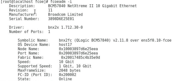
5. Verifying that the FCoE protocol has been negotiated
# Execute the fcoeadm -i command under the OS to query the information about the ports with FCoE configured and confirm that the protocol has been negotiated, as shown in Figure 27.
Figure 27 Querying the information about ports with FCoE configured
Interconnecting interconnect modules and FC switches
# Switch the external port XGE 1/1/1 to an FC port.
[H3C] interface Ten-GigabitEthernet 1/1/1
[H3C-Ten-GigabitEthernet1/1/1] port-type fc
The interface Ten-GigabitEthernet1/1/1, Ten-GigabitEthernet1/1/2, Ten-GigabitEth
ernet1/1/3, and Ten-GigabitEthernet1/1/4 will be deleted. Continue? [Y/N]:y
%Apr 3 18:49:23:050 2019 H3C OPTMOD/4/MODULE_IN: Fc1/1/1: The transceiver is 16
G_FC_SW_SFP.
# Configure the FC 1/1/1 port on interconnect module 1 to allow VSAN 1 to pass, and trust the 802.1p priority carried in packets.
[H3C-Fc1/1/1] port access vsan 1
[H3C-Fc1/1/1] fc mode np
[H3C-Fc1/1/1] qos trust dot1p
# Configure the FC 1/1/1 port on interconnect module 4 to allow VSAN 2 to pass, and trust the 802.1p priority carried in packets.
[H3C-Fc1/1/1] port access vsan 1
[H3C-Fc1/1/1] fc mode np
[H3C-Fc1/1/1] qos trust dot1p
# Save the configuration.
[H3C] save
The current configuration will be written to the device. Are you sure? [Y/N]:y
Please input the file name(*.cfg)[flash:/startup.cfg]
(To leave the existing filename unchanged, press the enter key):
# Check the information about the VFC port on the interconnect module, and confirm that the VFC port is UP.
[H3C]display interface vfc 1 brief
Brief information on VFC interface(s):
Admin Mode: E - e port; F - f port; NP - n port proxy
Oper Mode: TE - trunking e port; TF - trunking f port;
TNP - trunking n port proxy
Interface Admin Admin Oper Status Bind
Mode Trunk Mode Interface
Mode
Vfc1 F on -- UP XGE1/0/23
Querying the WWN number of the mezzanine card
Execute the display npv login command on the aggregation interconnect module to view the registration information about the node device connected to the downlink port of the aggregation interconnect module and the mapped uplink port. This command can be executed to display the detailed information, as shown in Table 2.
<H3C> display npv login
Server External
Interface VSAN FCID Node WWN Port WWN Interface
Vfc1 1 0x021101 20:00:f4:e9:D4:53:f1:c5 21:00:f4:e9:D4:53:f1:c5 Fc1/1/1
Configuring the Brocade switch
In this example, the Brocade switch uses the default settings. Ensure that Port 0 and Port 1 reside in the same FC zone.
Configuring 3Par storage
See "Configuring 3Par storage" for the process of configuring the 3Par storage server.
Configuring the OS
|
|
NOTE: · The following information provides the procedure for configuring multipath under Red Hat 7.5. Multipath can realize the loading balancing and reliability of the traffic between hosts and storage devices. For the procedure for configuring multipath and verifying the configuration under Windows, see "Configuring multipath and adding network disks on Windows Server." · Before configuration, ensure that the OS has installed the multipath tool, a built-in tool of most Linux systems. |
Preparation
Execute the fdisk -l command under the OS to view the two virtual volumes identified by the host, as shown in Figure 28.
Figure 28 Identifying the virtual volumes

|
|
NOTE: If no disk is found, execute the echo 1 > /sys/class/fc_host/hostnum/issue_lip command to manually refresh fc_host, where hostnum indicates the host number under the /sys/class/fc_host directory, such as host 1. |
Configuring multipath
1. Execute the following commands in turn to load the multipath server, set the polling mode, enable the multipath service, and format the path.
# modprobe dm-multipath
# modprobe dm-round-robin
# service multipathd start
# multipath –v2
|
|
NOTE: If it is prompted that the multipath.conf file does not exist under the Red Hat operating system, you can copy the file from another location and deliver it again, as shown in Figure 29. |
Figure 29 Handling the case when the multipath.conf file does not exist
2. Execute the following command to reboot the multipath server.
# systemctl restart multipathd.service
Verifying the configuration
After configuring the multipath, execute the fdisk -l command again. You can see a new mpatha volume, indicating that the system can access virtual volumes through multiple paths, as shown in Figure 30.
Figure 30 Viewing the mpatha volume

Example: Configuring FCoE (uplinking the aggregation interface of interconnect modules to FC switches)
Network requirement
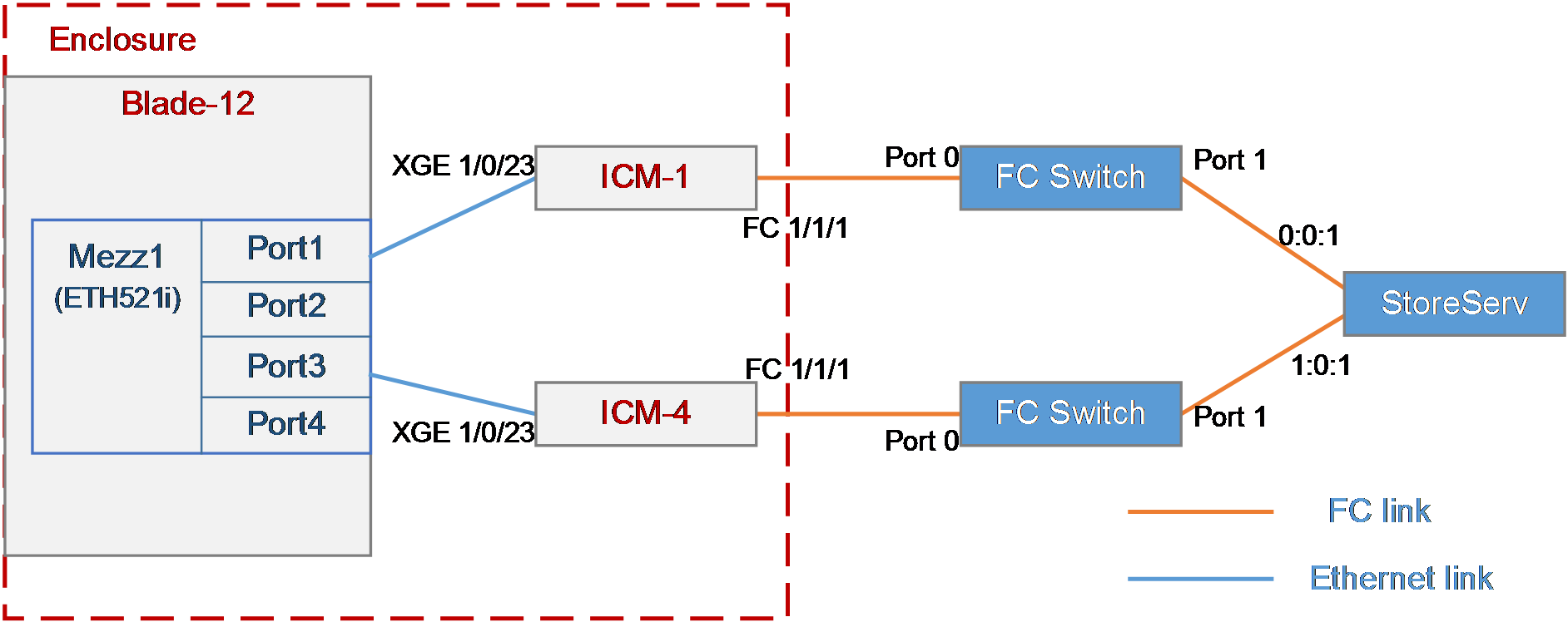
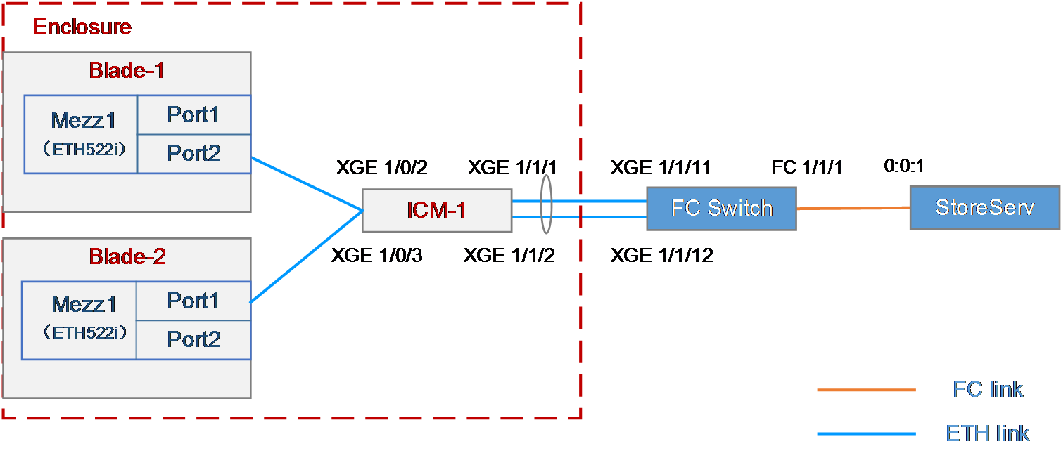
As shown in Figure 31, the blade servers and aggregation interconnect module are installed in the H3C B16000 blade server chassis. The blade servers are installed in slot 1 and slot 2, the aggregation interconnect module is installed in slot 1, and the mezzanine cards are installed in the mezzanine card slot 1 of the blade servers. The XGE 1/1/1 and XGE 1/1/2 ports of the interconnect module uplink the XGE 1/1/11 and XGE 1/1/12 ports of the FC switch. The FC 1/1/1 port of the FC switch is connected to the 0:0:1 port of the FC storage device.
In this example, the following devices and modules are used: blade server (H3C UniServer B5700 G3), mezzanine card (NIC-ETH522i-Mb-2*10G, "ETH522i"), aggregation interconnect module (BX720EF), FC switch (H3C S6800), and FC storage device (H3C CF8840 from the HPE 3Par StoreServ family).
The following requirements are expected to be met:
· Mounts storage volumes on the 3Par storage to the blade server to realize lossless remote storage.
· Breaks through the single-port traffic bottleneck of aggregation interconnect modules, so that the FCoE links of multiple blade servers share the same uplink aggregation interface.
Figure 31 Network diagram uplinking the aggregation interface of interconnect modules to FC switches
Analysis
· To mount 3Par storage volumes on the blade server, you need to build an FC link between the blade server and the 3Par storage to enable the transmission of FCoE traffic, which requires the following settings:
¡ Configure FCoE-related settings on the blade server and mezzanine card.
¡ Configure the FCoE function on the aggregation interconnect module to create the VFC port for transmitting the FC traffic.
¡ Configure the FC function on the FC switch to ensure FC link connectivity.
¡ Create a storage volume on the 3Par so that the blade server's OS can automatically recognize the storage volume.
· To break through the single-port traffic bottleneck of aggregation interconnect modules, you need to aggregate multiple physical ports of aggregation interconnect modules to form an aggregation interface, so that FCoE links of multiple blade servers can share the same aggregation interface to realize bandwidth aggregation and load sharing.
· To transmit storage data traffic of a SAN network over Ethernet links without losses, you need to create VFC ports and bind them with Ethernet ports. As a best practice, configure the PFC and ETS functions of DCBX and auto-negotiation modes on the internal ports of the aggregation switch modules.
Software versions used
This example was created and verified on versions SWITCH_SYS-1.00.11 and OM-1.00.11 of interconnect modules.
Configuration precautions
· Before adding a storage volume, ensure that the blade server has installed the OS and the appropriate network adapter driver, so that the OS can identify the ETH522i network adapter correctly. For details about installing the OS, see H3C Servers Operating System Installation Guide. For details about installing the network adapter driver, see ETH522i Mezzanine Card Module User Guide.
· After mounting the storage volumes and replacing existing storage volumes on the 3Par with new ones, reboot the OS of the blade server to identify the new volumes.
· As a best practice, disable the STP function of the internal ports on the interconnect modules, to prevent the rebooting or plugging in/out of the blade server from causing the STP of the interconnect modules to start calculating and resulting in short disconnection of external ports on the interconnect modules.
· Some packets are transmitted through VLAN 1 during the negotiation of the FCoE protocol. To ensure correct protocol negotiation, do not modify the relevant default settings of VLAN 1 to ensure normal communication of VLAN 1 traffic between the interconnect modules and blade servers.
· If you configure both FC ports and VFC ports on your devices, execute the qos trust dot1p command to enable normal PFC of the VFC ports.
Configuration procedure
Querying port information
Query the correspondence among mezzanine cards, internal ports of interconnect modules, and network adapters under the OS according to "Querying port relations."
It can be learned that:
· In this example, Port 1 of mezzanine card 1 on blade server 1 and Port 1 of mezzanine card 1 on blade server 2 are used and are named ens5f0 and ens5f1 under the OS, respectively.
· In this example, Ten-gigabitethernet 1/0/2, Ten-gigabitethernet 1/0/3, Ten-gigabitethernet 1/1/1, and Ten-gigabitethernet 1/1/2 ports of interconnect module 1 are used.
· In this example, Ten-gigabitethernet 1/1/11, Ten-gigabitethernet 1/1/12, and FC 1/1/1 ports of the H3C S6800 switch are used.
Configuring the mezzanine card
|
|
NOTE: · In this example, Red Hat 7.5 is installed on the blade server and used as an example in the following steps. · When Windows Server is installed on a blade server, there is no need to configure the mezzanine card under the system. |
1. Configure the FCoE function of ens5f0 and ens5f1 ports:
a. Under the /etc/fcoe directory, execute the cp cfg-ethX cfg-ethM command to copy and create the FCoE port configuration file. Where, cfg-ethM indicates the port name for FCoE connection. In this example, the names are cfg-ens5f0 and cfg-ens5f1. The following contents use cfg-ens5f0 as an example to describe the configuration steps.
[root@localhost]# cd /etc/fcoe/
[root@localhost fcoe]# ls
cfg-ethx
[root@localhost fcoe]# cp cfg-ethx cfg-ens5f0
b. Execute the vi cfg-ethM command, edit and save the FCoE port configuration file, and ensure that FCOE_ENABLE = yes, and DCB_REQUIRED = no, as shown in Figure 32.
[root@localhost fcoe]# vi cfg-ens5f0
Figure 32 Editing the FCoE port configuration file

c. Execute the lldptool set-lldp -i ethM adminStatus=disabled command to set the LLDP admin status of the port to disabled. Then, check the configuration value of adminStatus of ethM in the /var/lib/lldpad/lldpad.conf configuration file. If it is zero, the command is executed successfully. If it is not, manually add a line "adminStatus = 0" to the "ethM" entry under "lldp" in the configuration file, as shown in Figure 33.
[root@localhost fcoe]# lldptool set-lldp –i ens5f0 adminStatus=disabled
Figure 33 Disabling the LLDP admin status

d. Execute the service fcoe restart and service lldpad restart commands to restart the FCoE and LLDP services.
[root@localhost fcoe]# service lldpad restart
[root@localhost fcoe]# service fcoe restart
e. Execute the chkconfig fcoe on and chkconfig lldpad on commands to automatically load the FCoE and LLDP services during the boot phase.
[root@localhost fcoe]# chkconfig fcoe on
[root@localhost fcoe]# chkconfig lldpad on
Configuring the aggregation interconnect module
Interconnecting the aggregation interconnect module and mezzanine cards
1. Configuring FCoE-related settings and ports
<H3C> system-view
# Configure the FCoE mode of the switch to NPV.
[H3C] fcoe-mode npv
# Create the VSAN on interconnect module 1. In this example, VSAN 1 is created.
[H3C] vsan 1
[H3C-vsan1] quit
# Create VLAN 10 on interconnect module 1 to map VSAN 1, and enable the FCoE function on VLAN 10.
[H3C] vlan 10
[H3C-vlan10] fcoe enable vsan 1
[H3C-vlan10] quit
# Create VFC ports on interconnect module 1 and bind them with XGE 1/0/2 and XGE 1/0/3 internal ports.
[H3C] interface vfc 1
[H3C-Vfc1] bind interface Ten-gigabitethernet1/0/2
[H3C-Vfc1] port trunk vsan 1
[H3C-Vfc1] quit
[H3C] interface vfc 2
[H3C-Vfc2] bind interface Ten-gigabitethernet1/0/3
[H3C-Vfc2] port trunk vsan 1
[H3C-Vfc2] quit
# Configure the internal physical ports of interconnect module 1 to the trunk mode and allow VLAN 10 to pass.
[H3C] interface range Ten-GigabitEthernet 1/0/2 Ten-GigabitEthernet 1/0/3
[H3C-if-range] port link-type trunk
[H3C-if-range] port trunk permit vlan 10
[H3C-if-range] undo stp enable
[H3C-if-range] quit
2. Deploying DCBX
# Enable LLDP function globally.
[H3C] lldp global enable
# Create a Layer 2 ACL named DCBX and create rules for it to match FCoE packets (protocol number 0x8906) and FIP packets (protocol number 0x8914).
[H3C] acl mac name DCBX
[H3C-acl-mac-DCBX] rule 0 permit type 8906 ffff
[H3C-acl-mac-DCBX] rule 5 permit type 8914 ffff
[H3C-acl-mac-DCBX] quit
# Define a class named DCBX, the relation between the rules under it is OR, and define it to match the ACL named DCBX.
[H3C] traffic classifier DCBX operator or
[H3C-classifier-DCBX] if-match acl mac name DCBX
[H3C-classifier-DCBX] quit
# Define a stream behavior named DCBX and set the priority of the marked packets 802.1p to 3.
[H3C] traffic behavior DCBX
[H3C-behavior-DCBX] remark dot1p 3
[H3C-behavior-DCBX] quit
# Define a QoS policy named DCBX, specify the DCBX-like stream behavior as DCBX, and specify the policy as DCBX mode.
[H3C] qos policy DCBX
[H3C-qospolicy-DCBX] classifier DCBX behavior DCBX mode dcbx
[H3C-qospolicy-DCBX] quit
# Enable the LLDP function on the physical port, and configure the bound physical port to allow it to carry DCBX TLV fields when sending LLDP packets.
[H3C] interface range Ten-GigabitEthernet 1/0/2 Ten-GigabitEthernet 1/0/3
[H3C-if-range] lldp tlv-enable dot1-tlv dcbx
[H3C-if-range] qos apply policy DCBX outbound
[H3C-if-range] quit
3. Deploying PFC
|
|
NOTE: The WGE 1/1/1 to WGE 1/1/8 ports of the BX1020EF switch module does not support the PFC function. Therefore, do not use these ports to configure FCoE networking in actual situations. Otherwise, the network may not work correctly. |
# Configure the function to enable PFC through automatic negotiation with the server on the physical ports, enable the PFC function for 802.1p with priority set to 3, and configure to trust packets with the 802.1p priority.
[H3C] interface range Ten-GigabitEthernet 1/0/2 Ten-GigabitEthernet 1/0/3
[H3C-if-range] priority-flow-control auto
[H3C-if-range] priority-flow-control no-drop dot1p 3
[H3C-if-range] qos trust dot1p
[H3C-if-range] quit
4. Deploying ETS
# Configure the mapping from 802.1p priority to local priority, map 802.1p priority 3 to local priority 1, and map other 802.1p priorities to local priority 0.
[H3C] qos map-table dot1p-lp
[H3C-maptbl-dot1p-lp] import 3 export 1
[H3C-maptbl-dot1p-lp] import 0 export 0
[H3C-maptbl-dot1p-lp] import 1 export 0
[H3C-maptbl-dot1p-lp] import 2 export 0
[H3C-maptbl-dot1p-lp] import 4 export 0
[H3C-maptbl-dot1p-lp] import 5 export 0
[H3C-maptbl-dot1p-lp] import 6 export 0
[H3C-maptbl-dot1p-lp] import 7 export 0
[H3C-maptbl-dot1p-lp] quit
# On the physical port, configure other queues to SP scheduling.
[H3C] interface range Ten-GigabitEthernet 1/0/2 Ten-GigabitEthernet 1/0/3
[H3C-if-range] qos wrr af2 group sp
[H3C-if-range] qos wrr af3 group sp
[H3C-if-range] qos wrr af4 group sp
[H3C-if-range] qos wrr ef group sp
[H3C-if-range] qos wrr cs6 group sp
[H3C-if-range] qos wrr cs7 group sp
[H3C-if-range] quit
5. Verifying that the FCoE protocol has been negotiated
# Execute the fcoeadm -i command under the OS to query the information about the ports with FCoE configured and confirm that the protocol has been negotiated, as shown in Figure 34.
Figure 34 Querying the information about ports with FCoE configured

Interconnecting aggregation interconnect modules and FC switches
# Create an aggregation group on interconnect module 1 and add the physical ports to the aggregation group.
[H3C]interface Bridge-Aggregation 1
[H3C-Bridge-Aggregation1]quit
[H3C]interface range Ten-GigabitEthernet 1/1/1 Ten-GigabitEthernet 1/1/2
[H3C-if-range]port link-aggregation group 1
[H3C-if-range]quit
# Create VFC ports on interconnect module 1 and bind them with aggregation group 1.
[H3C] interface vfc 3
[H3C-Vfc3]bind interface Bridge-Aggregation 1
[H3C-Vfc3]port trunk vsan 1
[H3C-Vfc3]fc mode np
[H3C-Vfc3]quit
# Configure aggregation group 1 on interconnect module 1 to the trunk mode and allow VLAN 10 to pass.
[H3C]interface Bridge-Aggregation 1
[H3C-Bridge-Aggregation1]port link-type trunk
Configuring Ten-GigabitEthernet1/1/1 done.
Configuring Ten-GigabitEthernet1/1/2 done.
[H3C-Bridge-Aggregation1]port trunk permit vlan 10
Configuring Ten-GigabitEthernet1/1/1 done.
Configuring Ten-GigabitEthernet1/1/2 done.
[H3C-Bridge-Aggregation1]undo stp enable
[H3C-Bridge-Aggregation1]quit
# Save the configuration.
[H3C] save
The current configuration will be written to the device. Are you sure? [Y/N]:y
Please input the file name(*.cfg)[flash:/startup.cfg]
(To leave the existing filename unchanged, press the enter key):
Configuring the H3C S6800 switch
Interconnecting H3C S6800 switches and aggregation interconnect modules
# Configure the FCoE mode of the H3C S6800 switch to FCF.
<H3C> system-view
[H3C] fcoe-mode fcf
# Create VSAN on the H3C S6800 switch and enable the default-zone function in the VSAN. In this example, VSAN 1 is created.
[H3C] vsan 1
[H3C-vsan1] zone default-zone permit
[H3C-vsan1] quit
# Create VLAN 10 on the H3C S6800 switch to map the VSAN 1 and enable the FCoE function on VLAN 10.
[H3C] vlan 10
[H3C-vlan10] fcoe enable vsan 1
[H3C-vlan10] quit
# Create an aggregation group on the H3C S6800 switch and add the physical ports to the aggregation group.
[H3C]interface Bridge-Aggregation 1
[H3C-Bridge-Aggregation1]quit
[H3C]interface range Ten-GigabitEthernet 1/1/11 Ten-GigabitEthernet 1/1/12
[H3C-if-range]port link-aggregation group 1
[H3C-if-range]quit
# Create VFC ports on the H3C S6800 switch and bind them with aggregation group 1.
[H3C] interface vfc 3
[H3C-Vfc3]bind interface Bridge-Aggregation 1
[H3C-Vfc3]port trunk vsan 1
[H3C-Vfc3]fc mode f
[H3C-Vfc3]quit
# Configure aggregation group 1 on interconnect module 1 to the trunk mode and allow VLAN 10 to pass.
[H3C]interface Bridge-Aggregation 1
[H3C-Bridge-Aggregation1]port link-type trunk
Configuring Ten-GigabitEthernet1/1/11 done.
Configuring Ten-GigabitEthernet1/1/12 done.
[H3C-Bridge-Aggregation1]port trunk permit vlan 10
Configuring Ten-GigabitEthernet1/1/11 done.
Configuring Ten-GigabitEthernet1/1/12 done.
[H3C-Bridge-Aggregation1]undo stp enable
[H3C-Bridge-Aggregation1]quit
# Check the information about the VFC port on interconnect module 1, and confirm that the VFC port is UP.
[H3C]display interface vfc brief
Brief information on VFC interface(s):
Admin Mode: E - e port; F - f port; NP - n port proxy
Oper Mode: TE - trunking e port; TF - trunking f port;
TNP - trunking n port proxy
Interface Admin Admin Oper Status Bind
Mode Trunk Mode Interface
Mode
Vfc3 NP on TNP UP BAGG1
Vfc1 F on TF UP XGE1/0/2
Vfc2 F on TF UP XGE1/0/3
Interconnecting H3C S6800 switches and 3Par storage
# Switch the physical port connecting the H3C S6800 switch and 3Par storage to an FC port.
[H3C] interface Ten-GigabitEthernet 1/1/1
[H3C-Ten-GigabitEthernet1/1/1] port-type fc
The interface Ten-GigabitEthernet1/1/1, and Ten-GigabitEthernet1/1/2 will be deleted. Continue? [Y/N]:y
%Apr 3 18:49:23:050 2019 H3C OPTMOD/4/MODULE_IN: Fc1/1/1: The transceiver is 16
G_FC_SW_SFP.
# Configure the FC 1/1/1 port on the H3C S6800 switch to allow VSAN 1 to pass, and trust the 802.1p priority carried in packets.
[H3C-Fc1/1/1] port trunk mode on
[H3C-Fc1/1/1] port trunk vsan 1
[H3C-Fc1/1/1] fc mode f
[H3C-Fc1/1/1] qos trust dot1p
# Save the configuration.
[H3C] save
The current configuration will be written to the device. Are you sure? [Y/N]:y
Please input the file name(*.cfg)[flash:/startup.cfg]
(To leave the existing filename unchanged, press the enter key):
# Check the information about the VFC and FC ports on the H3C S6800 switch and confirm that the VFC port is UP.
[H3C]display interface vfc brief
Brief information on VFC interface(s):
Admin Mode: E - e port; F - f port; NP - n port proxy
Oper Mode: TE - trunking e port; TF - trunking f port;
TNP - trunking n port proxy
Interface Admin Admin Oper Status Bind
Mode Trunk Mode Interface
Mode
Vfc3 F on TF UP BAGG1
[H3C]display interface Fc brief
Brief information on FC interface(s):
Admin Mode: auto - auto; E - e port; F - f port; NP - n port proxy
Oper Mode: E - e port; F - f port; NP - n port proxy;
TE - trunking e port; TF - trunking f port;
TNP - trunking n port proxy
Interface VSAN Admin Admin Oper Oper Status SAN-Aggregation
Mode Trunk Mode Speed
Mode
Fc1/1/1 1 F on F 16G UP
Querying the WWN number of the mezzanine card
Execute the display npv login command on the aggregation interconnect module to view the registration information about the node device connected to the downlink port of the aggregation interconnect module and the mapped uplink port. This command can be executed to display the detailed information, as shown in Table 2.
<H3C> display npv login
Server External
Interface VSAN FCID Node WWN Port WWN Interface
Vfc1 1 0x021101 20:00:f4:e9:D4:53:f1:c5 21:00:f4:e9:D4:53:f1:c5 Vfc3
Vfc2 1 0x021102 20:00:f4:e9:D4:53:f1:c5 21:00:f4:e9:D4:53:f1:c6 Vfc3
Configuring 3Par storage
See "Configuring 3Par storage" for the process of configuring the 3Par storage server.
Configuring the OS
Execute the fdisk -l command under the OS to view the two virtual volumes identified by the host, as shown in Figure 35.
Figure 35 Identifying the virtual volumes

|
|
NOTE: If no disk is found, execute the echo 1 > /sys/class/fc_host/hostnum/issue_lip command to manually refresh fc_host, where hostnum indicates the host number under the /sys/class/fc_host directory, such as host 1. |
Verifying the configuration
Identifying storage volumes
As shown in Figure 36, execute the fdisk -l command under the OS to view the two virtual volumes identified by the host, indicating that the server-to-storage FC link is connected and the storage volumes are mounted.
Figure 36 Identifying the virtual volumes

Verifying the configuration of the aggregation group
After configuring the aggregation interfaces, check the information about the VFC port on interconnect module 1, and confirm that the VFC port is UP.
[H3C]display interface vfc brief
Brief information on VFC interface(s):
Admin Mode: E - e port; F - f port; NP - n port proxy
Oper Mode: TE - trunking e port; TF - trunking f port;
TNP - trunking n port proxy
Interface Admin Admin Oper Status Bind
Mode Trunk Mode Interface
Mode
Vfc3 NP on TNP UP BAGG1
Vfc1 F on TF UP XGE1/0/2
Vfc2 F on TF UP XGE1/0/3
# Display the details of the VFC3 aggregation interface.
<Sysname> display interface vfc 3
Vfc1
Current state: UP
Line protocol state: UP
Description: Vfc3 Interface
Bandwidth: 200000000kbps
Maximum transmission unit: 2112
Internet protocol processing: Disabled
Link layer protocol is FC
Port WWN is 66:66:66:63:66:64:61:30
FC mode is NP, state is NP
Support the VSAN protocol
VSAN tagging mode is Tagging
VFP common VSAN: 1
Bound interface is GigabitEthernet1/0/2, Bound MAC is 000c-2933-eacd
VSAN of physical-UP state: 1
Last clearing of counters: Never
The above information indicates that the VFC port is UP, and the VFC3 aggregation interface has a bandwidth that is the sum of the two physical ports. The two ports can share the traffic load.
Example: Configuring FCoE (connecting the aggregation switch module to both the FC switch and Ethernet switch)
Network requirement
As shown in Figure 37, a blade server and an aggregation switch module are installed in the H3C B16000 blade server chassis. The specific networking is as follows:
· The blade server is installed in slot 12. It deploys the VMware ESXi operating system and creates a Linux system virtual machine.
· A mezzanine card supporting NPAR is installed in the mezzanine card slot 1 of the blade server.
· The aggregation switch module is installed in slot 1.
· The aggregation switch module is connected to the Ethernet switch and the FC switch, and the blade server is connected to the VMware management network, the VMware service network, and the storage network through the aggregation switch module.
In this example, the following devices and modules are used: blade server (H3C UniServer B5700 G3), mezzanine card (NIC-ETH521i-Mb-4*10G, "ETH521i"), aggregation switch module (BX720EF), FC switch (Brocade 6510), and FC storage device (H3C CF8840 from the HPE 3Par StoreServ family).
The following requirements are expected to be met:
· The NPAR function supported by the mezzanine card on the blade server enables the mixed use of Ethernet and FCoE on a single port.
· Mounts storage volumes on the 3Par storage to the blade server to realize lossless remote storage.
· The blade server can communicate with the VMware management network and the VMware service network, and can separate management-related and service-related traffic.
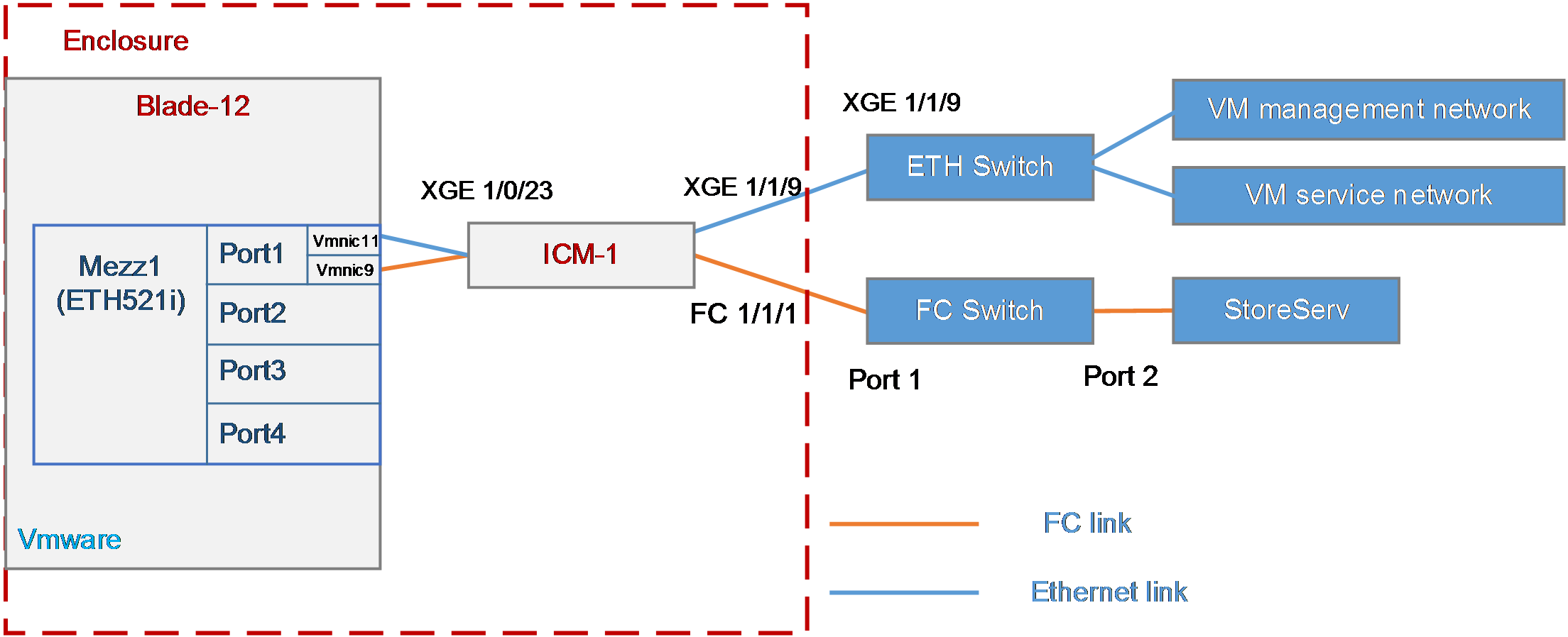
Analysis
· The NPAR function supported by the mezzanine card enables the mixed use of Ethernet and FCoE on a single port. To achieve this, you need to enable the NPAR function on the mezzanine card, split one physical port into two virtual ports, and configure the virtual ports to NIC and FCoE, respectively.
· To mount a 3Par storage volume to the blade server, build an FC link between the blade server and the 3Par storage, and create a storage volume on 3Par. Then, the OS of the blade server can automatically identify the storage volume. An FC link is divided into three segments:
¡ In this example, an aggregation switch module is used, and there is an Ethernet link between the blade server and the aggregation switch module. Therefore, the FCoE function needs to be configured on the mezzanine card and the aggregation switch module to transmit FC traffic.
¡ In this example, the aggregation switch module is directly connected to the FC switch. You need to configure the mode of the port connecting the aggregation switch module and the FC switch to NPV.
¡ In this example, the FC switch is directly connected to the storage. You can use the default settings.
· To transmit storage data traffic of a SAN network over Ethernet links without losses, you need to create VFC ports and bind them with Ethernet ports. As a best practice, configure the PFC and ETS functions of DCBX and auto-negotiation modes on the internal ports of the aggregation switch modules.
· To enable the blade server to communicate with the VMware management network and the VMware service network, you need to build Ethernet links between them. To separate management-related and service-related traffic, you need to configure VLAN on mezzanine cards on the blade server, aggregation switch module, and Ethernet switch to ensure smooth Ethernet services.
Software version
This example was configured and verified on the SWITCH_SYS-1.02.04 version of the interconnect module.
Configuration precautions
· Before adding a storage volume, ensure that the blade server has installed the OS and the appropriate network adapter driver, so that the OS can identify the ETH521i network adapter correctly. For details about installing the OS, see H3C Servers Operating System Installation Guide. For details about installing the network adapter driver, see ETH521i Mezzanine Card Module User Guide.
· After mounting the storage volumes and replacing existing storage volumes on the 3Par with new ones, reboot the OS of the blade server to identify the new volumes.
· As a best practice, disable the STP function of the internal ports on the aggregation switch modules, to prevent the rebooting or plugging in/out of the blade server from causing the STP of the aggregation switch modules to start calculating and resulting in short disconnection of external ports on the aggregation switch modules.
· Some packets are transmitted through VLAN 1 during the negotiation of the FCoE protocol. To ensure correct protocol negotiation, do not modify the relevant default settings of VLAN 1 to ensure normal communication of VLAN 1 traffic between the aggregation switch modules and the blade server.
· If you configure both FC ports and VFC ports on your devices, execute the qos trust dot1p command to enable the VFC ports to control PFC traffic correctly.
Configuration procedure
Enabling the NPAR function of the mezzanine card
For a detailed procedure for enabling the NPAR function of mezzanine cards, see ETH521i Mezzanine Card Module User Guide. In this example, the physical port 1 of the mezzanine card 1 uses the NPAR function to split the port into two virtual ports.
1. Enter the BIOS page, click the Advanced tab, and select NIC-ETH521i-Mb-4*10G.
2. As shown in Figure 38, select Partitioning Mode to change Default to NPAR.
Figure 38 Configuring the NPAR
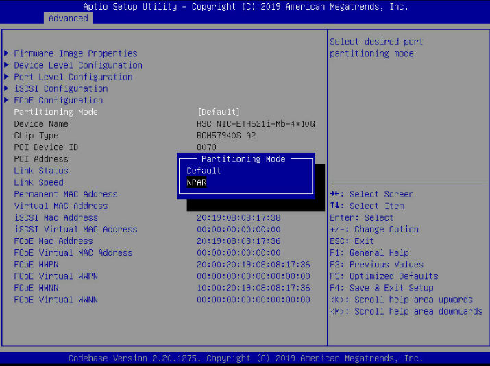
3. As shown in Figure 39, enter Partitions Configuration.
Figure 39 Configuring the mezzanine card
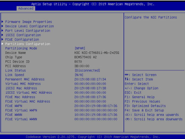
4. As shown in Figure 40, you can configure various PF parameters. In this example, PF1 and PF2 are set to Ethernet mode and FCoE mode, respectively.
|
|
NOTE: In this example, the mixed use of a single port is required by the networking. Therefore, relevant settings of Port 1 is configured. In actual application scenarios, you need to configure bonding to realize the redundancy of mezzanine card ports. |
Figure 40 Configuring the NPAR
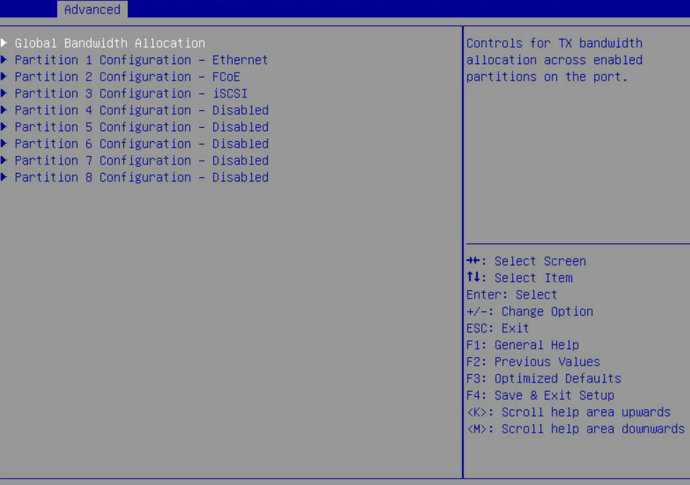
5. After configuration, the BIOS saves and restarts.
Querying port relations
Querying the port connection relation between the mezzanine card and the aggregation switch module
Please use the H3C networking query tool on the official network to check the port connection relation between the mezzanine card and the aggregation switch module, as shown in Figure 41. In this example, only Port 1 of the mezzanine card is configured.
Figure 41 Port connection relation between the mezzanine card and the aggregation switch module
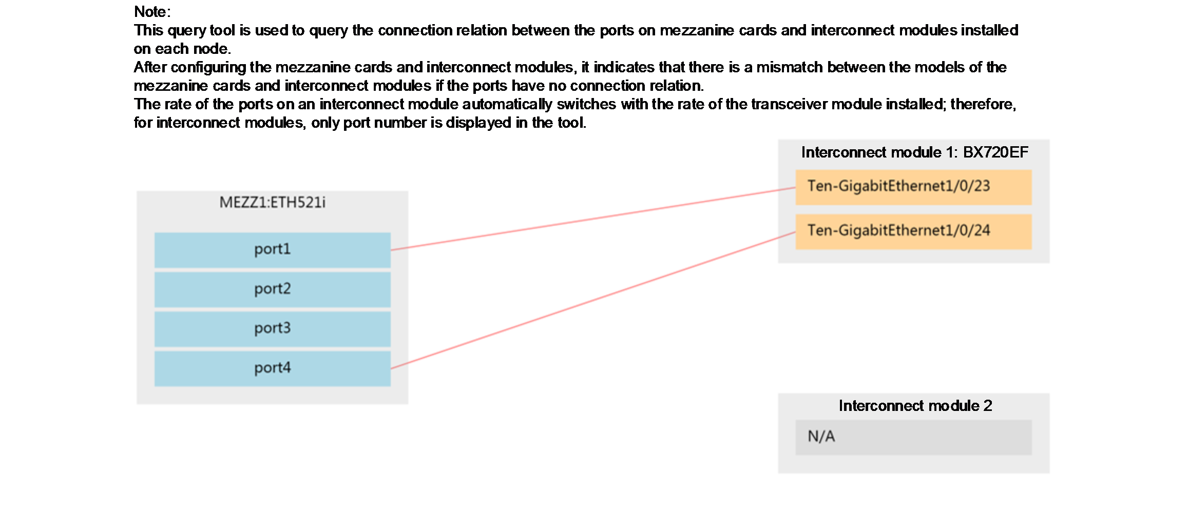
Querying the port correspondence between the network adapter and the mezzanine card under the OS
1. Log in to the OM Web page, click Blade server management, select blade server 12, and click Port mapping to query the MAC address of the mezzanine card port.
2. Query the MAC address of the mezzanine card port in the VMware operating system, and compare it with the MAC address queried in the above steps. You can learn the correspondence between the network adapter and the mezzanine card under the OS.
3. In summary, it can be learned that:
· In this example, Port 1 of the mezzanine card 1 is split into two virtual ports and they are named vmnic9 and vmnic11 under the OS, respectively.
· The Ten-gigabitethernet 1/0/23 port of aggregation switch module 1 is used in this example.
Configuring the mezzanine card
|
|
NOTE: In this example, VMware ESXi 6.5 is installed on the blade server and used as an example in the following steps. |
1. Configure the FCoE function of the virtual port vmnic9:
Log in to the VMware system via SSH, enter the esxcli fcoe nic enable -n vmnic9 and esxcli fcoe nic discover -n vmnic9 commands, and configure the FCoE function of virtual port vmnic9.
[root@localhost:~] esxcli fcoe nic enable -n vmnic9
true
[root@localhost:~] esxcli fcoe nic discover -n vmnic9
Discovery enabled on device 'vmnic9'
2. Configure the Ethernet service function of the virtual port vmnic11:
a. On the VMware page, select Network > Virtual Switch > Add Standard Virtual Switch to add a virtual switch with an uplink of vmnic11.
b. Select Network > Port Group > Add Port Group. Add a port group named eth_v11_vlanID_11, enter 11 in VLAN ID, and select eth_v11 for the virtual switch.
c. Select Virtual Machine > Operations > Edit Settings > Network Adapter. Select the port group eth_v11_vlanID_11, and save the settings.
d. Enter the operating system of the virtual machine and set the IP address of the network adapter on the virtual machine to 100.1.1.1/16.
Configuring storage services of the aggregation switch module
Interconnecting the aggregation switch module and the mezzanine card
1. Configure the FCoE function of the port:
# Enter the system view.
<H3C> system-view
# Configure the FCoE mode of the aggregation switch module to NPV.
[H3C] fcoe-mode npv
# Create the VSAN on the aggregation switch module. In this example, VSAN 1 is created.
[H3C] vsan 1
[H3C-vsan1] quit
# Create VLAN 10 on the aggregation switch module to map the VSAN 1 and enable the FCoE function on VLAN 10.
[H3C] vlan 10
[H3C-vlan10] fcoe enable vsan 1
[H3C-vlan10] quit
# Create a VFC port on the aggregation switch module, bind it to the internal port Ten-GigabitEthernet 1/0/23, and add the VFC port to VSAN 1 in trunk mode.
[H3C] interface vfc 1
[H3C-Vfc1] bind interface Ten-GigabitEthernet1/0/23
[H3C-Vfc1] port trunk vsan 1
[H3C-Vfc1] quit
# Configure the internal physical port on the aggregation switch module to the trunk mode and allow VLAN 10 to pass. As a best practice, disable the STP function of the internal ports on the aggregation switch module, to prevent the rebooting or plugging in/out of the blade server from causing the STP of the aggregation switch modules to start calculating.
[H3C] interface Ten-GigabitEthernet1/0/23
[H3C-Ten-GigabitEthernet1/0/23] port link-type trunk
[H3C-Ten-GigabitEthernet1/0/23] port trunk permit vlan 10
[H3C-Ten-GigabitEthernet1/0/23] undo stp enable
[H3C-Ten-GigabitEthernet1/0/23] quit
|
|
NOTE: The Ethernet port bound to the VFC port must be configured as follows: · The Ethernet port connecting the aggregation switch module and the server must be configured with PFC and ETS functions of DCBX and auto-negotiation modes. · The PFC function is forcibly enabled on the Ethernet port connecting the aggregation switch module and the switch. |
2. Deploying DCBX
# Enable LLDP function globally.
[H3C] lldp global enable
# Create a Layer 2 ACL named DCBX and create rules for it to match FCoE packets (protocol number 0x8906) and FIP packets (protocol number 0x8914).
[H3C] acl mac name DCBX
[H3C-acl-mac-DCBX] rule 0 permit type 8906 ffff
[H3C-acl-mac-DCBX] rule 5 permit type 8914 ffff
[H3C-acl-mac-DCBX] quit
# Define a class named DCBX, the relation between the rules under it is OR, and define it to match the ACL named DCBX.
[H3C] traffic classifier DCBX operator or
[H3C-classifier-DCBX] if-match acl mac name DCBX
[H3C-classifier-DCBX] quit
# Define a stream behavior named DCBX and set the priority of the marked packets 802.1p to 3.
[H3C] traffic behavior DCBX
[H3C-behavior-DCBX] remark dot1p 3
[H3C-behavior-DCBX] quit
# Define a QoS policy named DCBX, specify the DCBX-like stream behavior as DCBX, and specify the policy as DCBX mode.
[H3C] qos policy DCBX
[H3C-qospolicy-DCBX] classifier DCBX behavior DCBX mode dcbx
[H3C-qospolicy-DCBX] quit
# Enable the LLDP function on the internal port, and configure the port to allow it to send LLDP packets with DCBX TLV fields.
[H3C] interface Ten-GigabitEthernet 1/0/23
[H3C-Ten-GigabitEthernet1/0/23] lldp tlv-enable dot1-tlv dcbx
[H3C-Ten-GigabitEthernet1/0/23] qos apply policy DCBX outbound
[H3C-Ten-GigabitEthernet1/0/23] quit
3. Deploying PFC
|
|
NOTE: The WGE 1/1/1 to WGE 1/1/8 ports of the BX1020EF switch module does not support the PFC function. Therefore, do not use these ports to configure FCoE networking in actual situations. Otherwise, the network may not work correctly. |
# Configure the internal port to automatically negotiate with the server to confirm whether to enable the PFC function, set the 802.1p priority when the PFC function is enabled to 3, and set the port to trust the 802.1p priority carried in packets.
[H3C] interface Ten-GigabitEthernet 1/0/23
[H3C-Ten-GigabitEthernet1/0/23] priority-flow-control auto
[H3C-Ten-GigabitEthernet1/0/23] priority-flow-control no-drop dot1p 3
[H3C-Ten-GigabitEthernet1/0/23] qos trust dot1p
[H3C-Ten-GigabitEthernet1/0/23] quit
4. Deploying ETS
# Configure the mapping from 802.1p priority to local priority, map 802.1p priority 3 to local priority 1, and map other 802.1p priorities to local priority 0.
[H3C] qos map-table dot1p-lp
[H3C-maptbl-dot1p-lp] import 3 export 1
[H3C-maptbl-dot1p-lp] import 0 export 0
[H3C-maptbl-dot1p-lp] import 1 export 0
[H3C-maptbl-dot1p-lp] import 2 export 0
[H3C-maptbl-dot1p-lp] import 4 export 0
[H3C-maptbl-dot1p-lp] import 5 export 0
[H3C-maptbl-dot1p-lp] import 6 export 0
[H3C-maptbl-dot1p-lp] import 7 export 0
[H3C-maptbl-dot1p-lp] quit
# Configure WRR queues on the internal port to enable the bandwidth usage ratio of FCoE traffic to normal LAN traffic to be 2:1. Therefore, the weight of the two queues is set to 2:1.
[H3C] interface Ten-GigabitEthernet 1/0/23
[H3C-Ten-GigabitEthernet1/0/23] qos wrr af1 group 1 byte-count 2
[H3C-Ten-GigabitEthernet1/0/23] qos wrr be group 1 byte-count 1
# On the internal port, configure other queues to SP scheduling.
[H3C-Ten-GigabitEthernet1/0/23] qos wrr af2 group sp
[H3C-Ten-GigabitEthernet1/0/23] qos wrr af3 group sp
[H3C-Ten-GigabitEthernet1/0/23] qos wrr af4 group sp
[H3C-Ten-GigabitEthernet1/0/23] qos wrr ef group sp
[H3C-Ten-GigabitEthernet1/0/23] qos wrr cs6 group sp
[H3C-Ten-GigabitEthernet1/0/23] qos wrr cs7 group sp
[H3C-Ten-GigabitEthernet1/0/23] quit
Interconnecting the aggregation switch module and the FC switch
# Switch the external port Ten-GigabitEthernet 1/1/1 on the aggregation switch module to the FC port.
[H3C] interface Ten-GigabitEthernet 1/1/1
[H3C-Ten-GigabitEthernet1/1/1] port-type fc
The interface Ten-GigabitEthernet1/1/1, Ten-GigabitEthernet1/1/2, Ten-GigabitEth
ernet1/1/3, and Ten-GigabitEthernet1/1/4 will be deleted. Continue? [Y/N]:y
%Apr 3 18:49:23:050 2019 H3C OPTMOD/4/MODULE_IN: Fc1/1/1: The transceiver is 16
G_FC_SW_SFP.
# Configure FC 1/1/1 port to allow VSAN 1 to pass and trust the 802.1p priority carried in packets.
[H3C-Fc1/1/1] port access vsan 1
[H3C-Fc1/1/1] fc mode np
[H3C-Fc1/1/1] qos trust dot1p
# Save the configuration.
[H3C] save
The current configuration will be written to the device. Are you sure? [Y/N]:y
Please input the file name(*.cfg)[flash:/startup.cfg]
(To leave the existing filename unchanged, press the enter key):
# Check the information about the VFC port on the aggregation switch module, and confirm that the VFC port is UP.
[H3C]display interface vfc 1 brief
Brief information on VFC interface(s):
Admin Mode: E - e port; F - f port; NP - n port proxy
Oper Mode: TE - trunking e port; TF - trunking f port;
TNP - trunking n port proxy
Interface Admin Admin Oper Status Bind
Mode Trunk Mode Interface
Mode
Vfc1 F on -- UP XGE1/0/23
Querying the WWN number of the mezzanine card
Execute the display npv login command on the aggregation switch module to view the registration information about the node device connected to the downlink port of the aggregation switch module and the mapped uplink port.
<H3C> display npv login
Server External
Interface VSAN FCID Node WWN Port WWN Interface
Vfc1 1 0x021101 20:00:f4:e9:D4:53:f1:c5 21:00:f4:e9:D4:53:f1:c5 Fc1/1/1
Configuring the Brocade switch
In this example, the Brocade switch uses the default settings. Ensure that Port 0 and Port 1 reside in the same FC zone.
Configuring 3Par storage
See "Configuring 3Par storage" for the process of configuring the 3Par storage server.
Configuring Ethernet services of the aggregation switch module
|
|
NOTE: After the FC and FCoE functions are enabled in a VLAN, only FCoE traffic is forwarded in the VLAN. |
Interconnecting the aggregation switch module and the mezzanine card
# Create VLAN 11.
[H3C] vlan11
[H3C-vlan11]quit
# Configure the port Ten-GigabitEthernet 1/0/23 to allow VLAN 11 to pass.
[H3C] interface Ten-GigabitEthernet 1/0/23
[H3C-Ten-GigabitEthernet1/0/23] port trunk permit vlan 11
H3C-Ten-GigabitEthernet1/0/23] quit
# Configure the port Ten-GigabitEthernet 1/1/9 to a trunk port and allow VLAN 11 to pass.
[H3C] interface Ten-GigabitEthernet 1/1/9
[H3C-Ten-GigabitEthernet1/1/9] port link-type trunk
[H3C-Ten-GigabitEthernet1/1/9] port trunk permit vlan 11
[H3C-Ten-GigabitEthernet1/1/9] undo port trunk permit vlan 1
[H3C-Ten-GigabitEthernet1/1/9] undo stp enable
[H3C-Ten-GigabitEthernet1/1/9] quit
Configuring the aggregation switch
# Create VLAN 11.
[H3C] vlan11
[H3C-vlan2]quit
# Configure the port Ten-GigabitEthernet 1/1/9 to a trunk port and allow VLAN 11 to pass.
[H3C] interface Ten-GigabitEthernet 1/1/9
[H3C-Ten-GigabitEthernet1/1/9] port link-type trunk
[H3C-Ten-GigabitEthernet1/1/9] port trunk permit vlan 11
[H3C-Ten-GigabitEthernet1/1/9] undo port trunk permit vlan 1
[H3C-Ten-GigabitEthernet1/1/9] undo stp enable
[H3C-Ten-GigabitEthernet1/1/9] quit
# Create a VLAN port and set the port address to 100.1.1.1/24.
[H3C] interface vlan 11
[H3C-Vlan-interface11] ip address 100.1.1.2 255.255.255.0
[H3C-Vlan-interface11] quit
# Check the status of VLAN 2 port and confirm that the port is UP.
[H3C-Vlan-interface2]display interface vlan 11 brief
Brief information on interfaces in route mode:
Link: ADM - administratively down; Stby - standby
Protocol: (s) - spoofing
Interface Link Protocol Primary IP Description
Vlan11 UP UP 100.1.1.2
# Save the configuration.
[H3C] save
The current configuration will be written to the device. Are you sure? [Y/N]:y
Please input the file name(*.cfg)[flash:/startup.cfg]
(To leave the existing filename unchanged, press the enter key):
Verifying the configuration
Navigate to VMware > Storage > Device to view the storage volumes on 3Par.
In the OS of the virtual machine, ping VLAN 11 port on the aggregation switch. Verify that the port can be pinged successfully.
[root@localhost]# ping 100.1.1.2
PING 100.1.1.2(100.1.1.2) 56(84) bytes of data.
64bytes from 100.1.1.2: icmp_seq=1 ttl=255 time=0.808 ms
64bytes from 100.1.1.2: icmp_seq=2 ttl=255 time=0.691 ms
64bytes from 100.1.1.2: icmp_seq=3 ttl=255 time=0.732 ms
64bytes from 100.1.1.2: icmp_seq=4 ttl=255 time=0.679 ms
Example: Configuring FCoE (directly connecting the aggregation interconnect modules to 3Par storage)
Network requirement
As shown in Figure 42, a blade server and two aggregation interconnect modules are installed in the H3C B16000 blade server chassis. The blade server is installed in slot 12, two aggregation interconnect modules are installed in slot 1 and slot 4, and the mezzanine card is installed in the mezzanine card slot 1 of the blade server. The FC 1/1/1 port of each of the two aggregation interconnect modules is directly connected to the 0:0:1 or 1:0:1 port of the 3Par storage.
In this example, the following devices and modules are used: blade server (H3C UniServer B5700 G3), mezzanine card (NIC-ETH521i-Mb-4*10G, "ETH521i"), aggregation interconnect module (BX720EF), and FC storage device (H3C CF8840 from the HPE 3Par StoreServ family).
The following requirements are expected to be met:
The OS on the blade server can mount storage volumes on the 3Par to realize lossless remote storage, and you can still access data on the 3Par through the OS when any interconnect module fails.
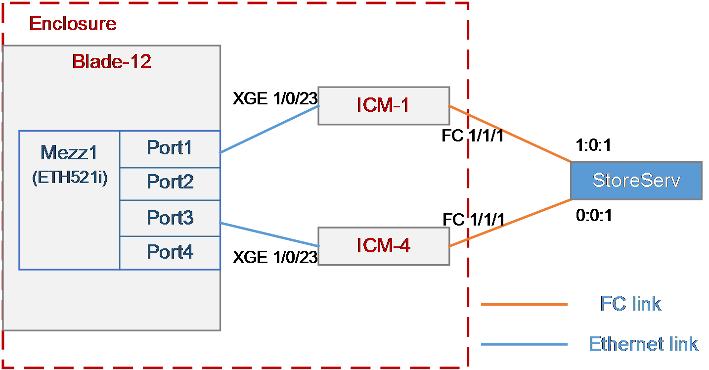
Analysis
· To mount a 3Par storage volume under the OS, build an FC link between the blade server and the 3Par storage, and create a storage volume on the 3Par storage. Then, the OS can automatically identify the storage volume.
· In this example, aggregation interconnect modules are used, and the blade server and interconnect modules are connected through Ethernet links. Therefore, you need to configure the FCoE function on mezzanine cards and interconnect modules to transmit FC traffic.
· The first eight external ports on the BX720EF aggregation interconnect module support FC/Ethernet handoff and need to be switched to the FC mode.
· In this example, the FC switch module is directly connected to the FC storage device. You need to configure the mode of the two interconnect modules to FCF.
· To ensure service continuity when any interconnect module fails, you need to configure the multipath function under the OS to improve network reliability.
· As a best practice, configure the PFC and ETS functions of DCBX and auto-negotiation modes on the internal ports of the interconnect modules, to transmit storage data traffic of a SAN network over Ethernet links without losses.
Software versions used
This example was created and verified on versions SWITCH_SYS-1.00.11 and OM-1.00.11 of interconnect modules.
Configuration precautions
· Before adding a storage volume, ensure that the blade server has installed the OS and the appropriate network adapter driver, so that the OS can identify the ETH521i network adapter correctly. For details about installing the OS, see H3C Servers Operating System Installation Guide. For details about installing the network adapter driver, see ETH521i Mezzanine Card Module User Guide.
· After mounting the storage volumes and replacing existing storage volumes on the 3Par with new ones, reboot the OS of the blade server to identify the new volumes.
· As a best practice, disable the STP function of the internal ports on the interconnect modules, to prevent the rebooting or plugging in/out of the blade server from causing the STP of the interconnect modules to start calculating and resulting in short disconnection of external ports on the interconnect modules.
· Some packets are transmitted through VLAN 1 during the negotiation of the FCoE protocol. To ensure correct protocol negotiation, do not modify the relevant default settings of VLAN 1 to ensure normal communication of VLAN 1 traffic between the interconnect modules and blade servers.
· If you configure both FC ports and VFC ports on your devices, execute the qos trust dot1p command to enable normal PFC of the VFC ports.
Configuration procedure
Querying port information
Query the correspondence among mezzanine cards, internal ports of interconnect modules, and network adapters under the OS according to "Querying port relations."
It can be learned that:
· In this example, Port 1 and Port 3 of mezzanine card 3 are used and are named ens5f0 and ens5f2 under the OS, respectively.
· Ten-gigabitethernet 1/0/23 ports of interconnect modules 1 and 4 are used in this example.
Configuring the mezzanine card
|
|
NOTE: · In this example, Red Hat 7.5 is installed on the blade server and used as an example in the following steps. · When Windows Server is installed on a blade server, there is no need to configure the mezzanine card under the system. |
1. Configure the FCoE function of ens5f0 and ens5f2 ports:
a. Under the /etc/fcoe directory, execute the cp cfg-ethX cfg-ethM command to copy and create the FCoE port configuration file. Where, cfg-ethM indicates the port name for FCoE connection. In this example, the names are cfg-ens5f0 and cfg-ens5f2. The following contents use cfg-ens5f0 as an example to describe the configuration steps.
[root@localhost]# cd /etc/fcoe/
[root@localhost fcoe]# ls
cfg-ethx
[root@localhost fcoe]# cp cfg-ethx cfg-ens5f0
b. Execute the vi cfg-ethM command, edit and save the FCoE port configuration file, and ensure that FCOE_ENABLE = yes, and DCB_REQUIRED = no, as shown in Figure 43.
[root@localhost fcoe]# vi cfg-ens5f0
Figure 43 Editing the FCoE port configuration file

c. Execute the lldptool set-lldp -i ethM adminStatus=disabled command to set the LLDP admin status of the port to disabled. Then, check the configuration value of adminStatus of ethM in the /var/lib/lldpad/lldpad.conf configuration file. If it is zero, the command is executed successfully. If it is not, manually add a line "adminStatus = 0" to the "ethM" entry under "lldp" in the configuration file, as shown in Figure 44.
[root@localhost fcoe]# lldptool set-lldp –i ens5f0 adminStatus=disabled
Figure 44 Disabling the LLDP admin status
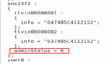
d. Execute the service fcoe restart and service lldpad restart commands to restart the FCoE and LLDP services.
[root@localhost fcoe]# service lldpad restart
[root@localhost fcoe]# service fcoe restart
e. Execute the chkconfig fcoe on and chkconfig lldpad on commands to automatically load the FCoE and LLDP services during the boot phase.
[root@localhost fcoe]# chkconfig fcoe on
[root@localhost fcoe]# chkconfig lldpad on
Configuring the interconnect module
Interconnecting interconnect modules and mezzanine cards
1. Configuring FCoE-related settings and ports
<H3C> system-view
# Configure the FCoE mode of the switch to FCF.
[H3C] fcoe-mode fcf
# Create the VSAN on interconnect module 1. In this example, create VSAN 1 and allow members in the default zone to access each other.
[H3C] vsan 1
[H3C-vsan1] zone default-zone permit
[H3C-vsan1] quit
# Create VLAN 10 on interconnect module 1 to map VSAN 1, and enable the FCoE function on VLAN 10.
[H3C] vlan 10
[H3C-vlan10] fcoe enable vsan 1
[H3C-vlan10] quit
# Create VFC ports on interconnect module 1, and bind them with internal ports XGE 1/0/23.
[H3C] interface vfc 1
[H3C-Vfc1] bind interface Ten-GigabitEthernet1/0/23
[H3C-Vfc1] port trunk vsan 1
[H3C-Vfc1] quit
# Configure the internal physical ports of interconnect module 1 to the trunk mode and allow VLAN 10 to pass.
[H3C] interface Ten-GigabitEthernet1/0/23
[H3C-Ten-GigabitEthernet1/0/23] port link-type trunk
[H3C-Ten-GigabitEthernet1/0/23] port trunk permit vlan 10
[H3C-Ten-GigabitEthernet1/0/23] undo stp enable
# Create the VSAN on interconnect module 4. In this example, create VSAN 2 and allow members in the default zone to access each other.
[H3C] vsan 2
[H3C-vsan2] zone default-zone permit
[H3C-vsan2] quit
# Create VLAN 20 on interconnect module 4 to map VSAN 2, and enable the FCoE function on VLAN 20.
[H3C] vlan 20
[H3C-vlan20] fcoe enable vsan 2
[H3C-vlan20] quit
# Create VFC ports on interconnect module 4, and bind them with internal ports XGE 1/0/23.
[H3C] interface vfc 2
[H3C-Vfc2] bind interface Ten-GigabitEthernet1/0/23
[H3C-Vfc2] port trunk vsan 2
[H3C-Vfc2] quit
# Configure the internal physical ports of interconnect module 4 to the trunk mode and allow VLAN 20 to pass.
[H3C] interface Ten-GigabitEthernet1/0/23
[H3C-Ten-GigabitEthernet1/0/23] port link-type trunk
[H3C-Ten-GigabitEthernet1/0/23] port trunk permit vlan 20
[H3C-Ten-GigabitEthernet1/0/23] undo stp enable
[H3C-Ten-GigabitEthernet1/0/23] quit
2. Deploying DCBX
# Enable LLDP function globally.
[H3C] lldp global enable
# Create a Layer 2 ACL named DCBX and create rules for it to match FCoE packets (protocol number 0x8906) and FIP packets (protocol number 0x8914).
[H3C] acl mac name DCBX
[H3C-acl-mac-DCBX] rule 0 permit type 8906 ffff
[H3C-acl-mac-DCBX] rule 5 permit type 8914 ffff
[H3C-acl-mac-DCBX] quit
# Define a class named DCBX, the relation between the rules under it is OR, and define it to match the ACL named DCBX.
[H3C] traffic classifier DCBX operator or
[H3C-classifier-DCBX] if-match acl mac name DCBX
[H3C-classifier-DCBX] quit
# Define a stream behavior named DCBX and set the priority of the marked packets 802.1p to 3.
[H3C] traffic behavior DCBX
[H3C-behavior-DCBX] remark dot1p 3
[H3C-behavior-DCBX] quit
# Define a QoS policy named DCBX, specify the DCBX-like stream behavior as DCBX, and specify the policy as DCBX mode.
[H3C] qos policy DCBX
[H3C-qospolicy-DCBX] classifier DCBX behavior DCBX mode dcbx
[H3C-qospolicy-DCBX] quit
# Enable the LLDP function on the aggregate interfaces, and configure the bound physical interfaces to allow the interface to send LLDP packets with DCBSX TLV fields.
[H3C] interface Ten-GigabitEthernet 1/0/23
[H3C-Ten-GigabitEthernet1/0/23] lldp tlv-enable dot1-tlv dcbx
[H3C-Ten-GigabitEthernet1/0/23] qos apply policy DCBX outbound
[H3C-Ten-GigabitEthernet1/0/23] quit
3. Deploying PFC
|
|
NOTE: The WGE 1/1/1 to WGE 1/1/8 ports of the BX1020EF switch module does not support the PFC function. Therefore, do not use these ports to configure FCoE networking in actual situations. Otherwise, the network may not work correctly. |
# Configure the function to enable PFC through automatic negotiation with the server on the physical ports, enable the PFC function for 802.1p with priority set to 3, and configure to trust packets with the 802.1p priority.
[H3C] interface Ten-GigabitEthernet 1/0/23
[H3C-Ten-GigabitEthernet1/0/23] priority-flow-control auto
[H3C-Ten-GigabitEthernet1/0/23] priority-flow-control no-drop dot1p 3
[H3C-Ten-GigabitEthernet1/0/23] qos trust dot1p
[H3C-Ten-GigabitEthernet1/0/23] quit
4. Deploying ETS
# Configure the mapping from 802.1p priority to local priority, map 802.1p priority 3 to local priority 1, and map other 802.1p priorities to local priority 0.
[H3C] qos map-table dot1p-lp
[H3C-maptbl-dot1p-lp] import 3 export 1
[H3C-maptbl-dot1p-lp] import 0 export 0
[H3C-maptbl-dot1p-lp] import 1 export 0
[H3C-maptbl-dot1p-lp] import 2 export 0
[H3C-maptbl-dot1p-lp] import 4 export 0
[H3C-maptbl-dot1p-lp] import 5 export 0
[H3C-maptbl-dot1p-lp] import 6 export 0
[H3C-maptbl-dot1p-lp] import 7 export 0
[H3C-maptbl-dot1p-lp] quit
# Configure other queues to SP scheduling on the physical interface bound to the aggregate interface.
[H3C] interface Ten-GigabitEthernet 1/0/23
[H3C-Ten-GigabitEthernet1/0/23] qos wrr af2 group sp
[H3C-Ten-GigabitEthernet1/0/23] qos wrr af3 group sp
[H3C-Ten-GigabitEthernet1/0/23] qos wrr af4 group sp
[H3C-Ten-GigabitEthernet1/0/23] qos wrr ef group sp
[H3C-Ten-GigabitEthernet1/0/23] qos wrr cs6 group sp
[H3C-Ten-GigabitEthernet1/0/23] qos wrr cs7 group sp
[H3C-Ten-GigabitEthernet1/0/23] quit
5. Verifying that the FCoE protocol has been negotiated
# Execute the fcoeadm -i command under the OS to query the information about the ports with FCoE configured and confirm that the protocol has been negotiated, as shown in Figure 45.
Figure 45 Querying the information about ports with FCoE configured

Interconnecting interconnect modules and 3Par
# Switch the external port XGE1/1/1 to an FC port.
[H3C] interface Ten-GigabitEthernet 1/1/1
[H3C-Ten-GigabitEthernet1/1/1] port-type fc
The interface Ten-GigabitEthernet1/1/1, Ten-GigabitEthernet1/1/2, Ten-GigabitEth
ernet1/1/3, and Ten-GigabitEthernet1/1/4 will be deleted. Continue? [Y/N]:y
%Apr 3 18:49:23:050 2019 H3C OPTMOD/4/MODULE_IN: Fc1/1/1: The transceiver is 16
G_FC_SW_SFP.
# Configure the FC 1/1/1 port on interconnect module 1 to allow VSAN 1 to pass, and trust the 802.1p priority carried in packets.
[H3C-Fc1/1/1] port access vsan 1
[H3C-Fc1/1/1] qos trust dot1p
# Configure the FC 1/1/1 port on interconnect module 4 to allow VSAN 2 to pass, and trust the 802.1p priority carried in packets.
[H3C-Fc1/1/1] port access vsan 1
[H3C-Fc1/1/1] qos trust dot1p
# Save the configuration.
[H3C] save
The current configuration will be written to the device. Are you sure? [Y/N]:y
Please input the file name(*.cfg)[flash:/startup.cfg]
(To leave the existing filename unchanged, press the enter key):
# Check the information about the VFC port on the interconnect module, and confirm that the VFC port is UP.
[H3C]display interface vfc 1 brief
Brief information on VFC interface(s):
Admin Mode: E - e port; F - f port; NP - n port proxy
Oper Mode: TE - trunking e port; TF - trunking f port;
TNP - trunking n port proxy
Interface Admin Admin Oper Status Bind
Mode Trunk Mode Interface
Mode
Vfc1 F on -- UP XGE1/0/23
Querying the WWN of the node connected to the FC switch module
Execute the display fc login command on the interconnect module to view the registration information about the node. Here we use interconnect module 1 as an example. This command can be executed to display the detailed information, as shown in Table 4.
<H3C> display fc login
Interface VSAN FCID Node WWN Port WWN
Fc1/1/1 1 0x200003 2f:f7:00:02:ac:02:28:66 21:01:00:02:ac:02:28:66
Vfc1 1 0x200002 20:00:f4:e9:d4:53:f1:c5 21:00:f4:e9:d4:53:f1:c5
Configuring 3Par storage
See "Configuring 3Par storage" for the process of configuring the 3Par storage server.
Configuring the OS
|
|
NOTE: · The following information provides the procedure for configuring multipath under Red Hat 7.5. Multipath can realize the loading balancing and reliability of the traffic between hosts and storage devices. For the procedure for configuring multipath and verifying the configuration under Windows, see "Configuring multipath and adding network disks on Windows Server." · Before configuration, ensure that the OS has installed the multipath tool, a built-in tool of most Linux systems. |
Preparation
Execute the fdisk -l command under the OS to view the two virtual volumes identified by the host, as shown in Figure 46.
Figure 46 Identifying the virtual volumes

|
|
NOTE: If no disk is found, execute the echo 1 > /sys/class/fc_host/hostnum/issue_lip command to manually refresh fc_host, where hostnum indicates the host number under the /sys/class/fc_host directory, such as host 1. |
Configuring multipath
1. Execute the following commands in turn to load the multipath server, set the polling mode, enable the multipath service, and format the path.
# modprobe dm-multipath
# modprobe dm-round-robin
# service multipathd start
# multipath –v2
|
|
NOTE: If it is prompted that the multipath.conf file does not exist under the Red Hat operating system, you can copy the file from another location and deliver it again, as shown in Figure 47. |
Figure 47 Handling the case when the multipath.conf file does not exist

2. Execute the following command to reboot the multipath server.
# systemctl restart multipathd.service
Verifying the configuration
After configuring the multipath, execute the fdisk -l command again. You can see a new mpatha volume, indicating that the system can access virtual volumes through multiple paths, as shown in Figure 48.
Figure 48 Viewing the mpatha volume
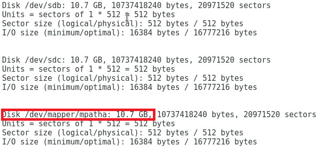
Example: Configuring FCoE (pass-through modules)
Network requirement
As shown in Figure 49, the blade server and Ethernet pass-through modules are installed in the H3C B16000 blade server chassis. The blade server is installed in slot 3, two Ethernet pass-through modules are installed in slot 1 and slot 4, and the mezzanine card is installed in the mezzanine card slot 1 of the blade server. The XGE 1/1/3 port of each of the two Ethernet pass-through modules is connected to the XGE 1/0/1 or XGE 1/0/2 port of the switch, and the switch is connected to the 0:0:1 port of 3Par storage through the FC 1/0/3 port.
In this example, the following devices and modules are used: blade server (H3C UniServer B5700 G3), mezzanine card (NIC-ETH522i-Mb-2*10G, "ETH522i"), Ethernet pass-through module (BT616E), switch (H3C S6800), and FC storage device (H3C CF8840 from the HPE 3Par StoreServ family).
In this example, the Red Hat Enterprise Linux 7.5 is installed on the blade server.
The following requirements are expected to be met:
The OS on the blade server can mount storage volumes on the 3Par to realize lossless remote storage, and you can still access data on the 3Par through OS on the blade server when any pass-through module fails.
Figure 49 Example: Configuring FCoE service (Ethernet pass-through modules)
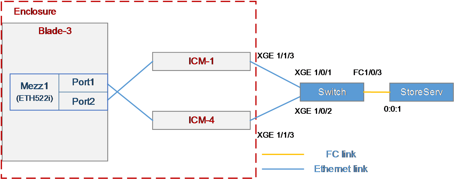
Analysis
· Before configuration, you need to query the correspondence between the mezzanine card, the external port of the pass-through module, and the mezzanine card port displayed under the OS, to ensure that the correct ports are configured and facilitate the verification after configuration.
· To mount a 3Par storage volume under the OS, build an FC link between the blade server and the 3Par storage, and create a storage volume on the 3Par storage. Then, the OS can automatically identify the storage volume.
· There is an Ethernet link between the blade server and the switch. Therefore, the FCoE function needs to be configured on the mezzanine card and the switch to transmit FC traffic.
· In this example, the H3C S 6800 switch is used. Its external ports support FC/Ethernet handoff, and you need to switch it to FC
· In this example, the switch is directly connected to the storage. You need to set the FCoE mode to FCF.
· To ensure service continuity when any pass-through module fails, you need to configure the multipath function under the OS to improve network reliability.
· As a best practice, configure the PFC and ETS functions of DCBX and auto-negotiation modes on the external ports connecting the switch and the interconnect module, to transmit storage data traffic of a SAN network over Ethernet links without losses.
Configuration precautions
· Make sure that the blade server's OS can recognize the ETH522i network adapter correctly. If it cannot, install the network adapter driver. For details, see ETH522i Mezzanine Card Module User Guide.
· After mounting the storage volumes and replacing existing storage volumes on the 3Par with new ones, reboot the OS of the blade server to identify the new volumes.
· Some packets are transmitted through VLAN 1 during the negotiation of the FCoE protocol. To ensure correct protocol negotiation, do not modify the relevant default settings of VLAN 1 to ensure normal communication of VLAN 1 traffic between the switch modules and the blade server.
· If you configure both FC ports and VFC ports on your devices, execute the qos trust dot1p command to enable normal PFC of the VFC ports.
Configuration procedure
Querying port information
Query the correspondence among mezzanine cards, internal ports of interconnect modules, and network adapters under the OS according to "Querying port relations."
It can be learned that:
· In this example, Port 1 and Port 2 of mezzanine card 1 on the blade server in slot 3 are used and are named ens5f0 and ens5f1 under the OS, respectively.
· The WWNs of Port 1 and Port 2 of mezzanine card 1 are 20007485C41E7521 and 20007485C41E7523, respectively.
Configuring the mezzanine card
The following information describes the procedure for configuring the FCoE function on mezzanine card ports under the OS of the blade server.
|
|
NOTE: · When Windows Server is installed on a blade server, there is no need to configure the mezzanine card under the system. |
Configure the FCoE function of ens5f0 and ens5f1 ports:
1. Under the /etc/fcoe directory, execute the cp cfg-ethX cfg-ethM command to copy and create the FCoE port configuration file. Where, cfg-ethM indicates the name of the configuration file for the port on which FCoE is enabled. In this example, the names are cfg-ens5f0 and cfg-ens5f1. The following contents use cfg-ens5f0 as an example to describe the configuration steps.
[root@localhost]# cd /etc/fcoe/
[root@localhost fcoe]# ls
cfg-ethx
[root@localhost fcoe]# cp cfg-ethx cfg-ens5f0
2. Execute the vi cfg-ethM command, edit and save the FCoE port configuration file, and ensure that FCOE_ENABLE = yes, and DCB_REQUIRED = no. Here we use cfg-ens5f0 as an example, as shown in Figure 50.
[root@localhost fcoe]# vi cfg-ens5f0
Figure 50 Editing the FCoE port configuration file

3. Execute the lldptool set-lldp -i ethM adminStatus=disabled command to set the LLDP admin status of the port to disabled. Where, ethM indicates the name of the port on which FCoE is enabled. In this example, the names are ens5f0 and ens5f1. The following contents use ens5f0 as an example to describe the configuration steps.
[root@localhost fcoe]# lldptool set-lldp –i ens5f0 adminStatus=disabled
4. Check that the adminStatus value of ethM in the /var/lib/lldpad/lldpad.conf file is 0.
¡ If it is, the command is executed successfully.
¡ If it is not, manually add a line "adminStatus = 0" to the "ethM" entry under "lldp" in the configuration file, as shown in Figure 51.
¡ If there is no lldpad.conf file in the /var/lib/lldpad/ path, execute the service fcoe restart and service lldpad restart commands to restart the FCoE and LLDP services. The lldpad.conf file will generate automatically. Then, manually add a line "adminStatus = 0" to the "ethM" entry under "lldp" in the configuration file, as shown in Figure 51.
Figure 51 Disabling the LLDP admin status
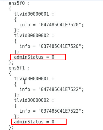
5. Execute the service fcoe restart and service lldpad restart commands to restart the FCoE and LLDP services.
[root@localhost fcoe]# service lldpad restart
[root@localhost fcoe]# service fcoe restart
6. Execute the chkconfig fcoe on and chkconfig lldpad on commands to automatically load the FCoE and LLDP services during the boot phase.
[root@localhost fcoe]# chkconfig fcoe on
[root@localhost fcoe]# chkconfig lldpad on
Configuring switch
Interconnecting the switch and the pass-through network board
1. Configuring the settings related to FCoE and ports
a. Configure the FCoE mode of the switch to FCF.
[H3C] fcoe-mode fcf
b. Create VSAN 1 and allow members in the default zone to access each other.
[H3C] vsan 1
[H3C-vsan1] zone default-zone permit
[H3C-vsan1] quit
c. Create VLAN 10, enable the FCoE function in VLAN 10, and map the VLAN to VSAN 1.
[H3C] vlan 10
[H3C-vlan10] fcoe enable vsan 1
[H3C-vlan10] quit
d. Create VFC ports and bind them with physical ports. In this example, XGE 1/0/1 and XGE 1/0/2 ports are used.
[H3C] interface vfc 1
[H3C-Vfc1] bind interface Ten-GigabitEthernet1/0/1
[H3C-Vfc1] port trunk vsan 1
[H3C-Vfc1] quit
[H3C] interface vfc 2
[H3C-Vfc1] bind interface Ten-GigabitEthernet1/0/2
[H3C-Vfc1] port trunk vsan 1
[H3C-Vfc1] quit
e. Configure the physical port to trunk mode and allow VLAN 10 to pass.
[H3C] interface Ten-GigabitEthernet1/0/1
[H3C-Ten-GigabitEthernet1/0/1] port link-type trunk
[H3C-Ten-GigabitEthernet1/0/1] port trunk permit vlan 10
[H3C-Ten-GigabitEthernet1/0/1] quit
[H3C] interface Ten-GigabitEthernet1/0/2
[H3C-Ten-GigabitEthernet1/0/2] port link-type trunk
[H3C-Ten-GigabitEthernet1/0/2] port trunk permit vlan 10
[H3C-Ten-GigabitEthernet1/0/2] quit
2. Deploying DCBX
a. Enable LLDP function globally.
[H3C] lldp global enable
b. Create a layer-2 ACL named DCBX and create rules for it to match FCoE packets (protocol number 0x8906) and FIP packets (protocol number 0x8914).
[H3C] acl mac name DCBX
[H3C-acl-mac-DCBX] rule 0 permit type 8906 ffff
[H3C-acl-mac-DCBX] rule 5 permit type 8914 ffff
c. Define a class named DCBX, the relation between the rules under it is OR, and define it to match the ACL named DCBX.
[H3C] traffic classifier DCBX operator or
[H3C-classifier-DCBX] if-match acl mac name DCBX
[H3C-classifier-DCBX] quit
d. Define a stream behavior named DCBX and set the 802.1p priority of the marked packets to 3.
[H3C] traffic behavior DCBX
[H3C-behavior-DCBX] remark dot1p 3
[H3C-behavior-DCBX] quit
e. Define a QoS policy named DCBX, specify the DCBX-like stream behavior as DCBX, and specify the policy as DCBX mode.
[H3C] qos policy DCBX
[H3C-qospolicy-DCBX] classifier DCBX behavior DCBX mode dcbx
[H3C-qospolicy-DCBX] quit
f. Enable the LLDP function on the physical port, and configure the port to allow it to send LLDP packets with DCBX TLV fields.
[H3C] interface Ten-GigabitEthernet 1/0/1
[H3C-Ten-GigabitEthernet1/0/1] lldp tlv-enable dot1-tlv dcbx
[H3C-Ten-GigabitEthernet1/0/1] qos apply policy DCBX outbound
[H3C-Ten-GigabitEthernet1/0/1] quit
[H3C] interface Ten-GigabitEthernet 1/0/2
[H3C-Ten-GigabitEthernet1/0/2] lldp tlv-enable dot1-tlv dcbx [H3C-Ten-GigabitEthernet1/0/2] qos apply policy DCBX outbound
[H3C-Ten-GigabitEthernet1/0/2] quit
3. Deploying PFC
|
|
NOTE: The WGE 1/1/1 to WGE 1/1/8 ports of the BX1020EF switch module does not support the PFC function. Therefore, do not use these ports to configure FCoE networking in actual situations. Otherwise, the network may not work correctly. |
Configure the physical port to automatically negotiate with the server to confirm whether to enable the PFC function, set the 802.1p priority when the PFC function is enabled to 3, and set the port to trust the 802.1p priority carried in packets.
[H3C] interface Ten-GigabitEthernet 1/0/1
[H3C-Ten-GigabitEthernet1/0/1] priority-flow-control auto
[H3C-Ten-GigabitEthernet1/0/1] priority-flow-control no-drop dot1p 3
[H3C-Ten-GigabitEthernet1/0/1] qos trust dot1p
[H3C-Ten-GigabitEthernet1/0/1] quit
[H3C] interface Ten-GigabitEthernet 1/0/2
[H3C-Ten-GigabitEthernet1/0/2] priority-flow-control auto
[H3C-Ten-GigabitEthernet1/0/2] priority-flow-control no-drop dot1p 3
[H3C-Ten-GigabitEthernet1/0/2] qos trust dot1p
[H3C-Ten-GigabitEthernet1/0/2] quit
4. Deploying ETS
a. Configure the mapping from 802.1p priority to local priority, map 802.1p priority 3 to local priority 1, and map other 802.1p priorities to local priority 0.
[H3C] qos map-table dot1p-lp
[H3C-maptbl-dot1p-lp] import 3 export 1
[H3C-maptbl-dot1p-lp] import 0 export 0
[H3C-maptbl-dot1p-lp] import 1 export 0
[H3C-maptbl-dot1p-lp] import 2 export 0
[H3C-maptbl-dot1p-lp] import 4 export 0
[H3C-maptbl-dot1p-lp] import 5 export 0
[H3C-maptbl-dot1p-lp] import 6 export 0
[H3C-maptbl-dot1p-lp] import 7 export 0
[H3C-maptbl-dot1p-lp] quit
b. On the physical port, configure other queues to SP scheduling.
[H3C] interface Ten-GigabitEthernet 1/0/1
[H3C-Ten-GigabitEthernet1/0/1] qos wrr af2 group sp
[H3C-Ten-GigabitEthernet1/0/1] qos wrr af3 group sp
[H3C-Ten-GigabitEthernet1/0/1] qos wrr af4 group sp
[H3C-Ten-GigabitEthernet1/0/1] qos wrr ef group sp
[H3C-Ten-GigabitEthernet1/0/1] qos wrr cs6 group sp
[H3C-Ten-GigabitEthernet1/0/1] qos wrr cs7 group sp
[H3C] interface Ten-GigabitEthernet 1/0/2
[H3C-Ten-GigabitEthernet1/0/2] qos wrr af2 group sp
[H3C-Ten-GigabitEthernet1/0/2] qos wrr af3 group sp
[H3C-Ten-GigabitEthernet1/0/2] qos wrr af4 group sp
[H3C-Ten-GigabitEthernet1/0/2] qos wrr ef group sp
[H3C-Ten-GigabitEthernet1/0/2] qos wrr cs6 group sp
[H3C-Ten-GigabitEthernet1/0/2] qos wrr cs7 group sp
Interconnecting the switch and 3Par storage
1. Execute the port-type fc command to switch the external port XGE 1/0/3 to an FC port and enter y for confirmation.
[H3C]interface Ten-GigabitEthernet 1/0/3
[H3C-Ten-GigabitEthernet1/0/3]port-type fc
2. Configure FC 1/0/3 port to allow VSAN 1 to pass and trust the 802.1p priority carried in packets.
[H3C-Fc1/0/3] port trunk vsan 1
[H3C-Fc1/0/3] qos trust dot1p
3. Save the configuration, and modify the configuration file name as required. For example, if you press Enter directly, the name is not modified.
[H3C]save
The current configuration will be written to the device. Are you sure? [Y/N]:y
Please input the file name(*.cfg)[flash:/startup.cfg]
(To leave the existing filename unchanged, press the enter key):
|
|
NOTE: After the configuration, execute the display current-configuration command to view the final configuration. |
Configuring 3Par storage
See "Configuring 3Par storage" for the process of configuring the 3Par storage server.
Configuring the OS
The following information provides the procedure for configuring multipath under the OS. Multipath can realize the loading balancing and reliability of the traffic between hosts and storage devices.
|
|
NOTE: · Before configuration, ensure that the OS has installed the multipath tool, a built-in tool of most Linux systems. |
Configuring multipath
Execute the following commands in turn to load the multipath server, set the polling mode, enable the multipath service, and format the path.
# modprobe dm-multipath
# modprobe dm-round-robin
# service multipathd start
# multipath -v2
|
|
NOTE: If it is prompted that the multipath.conf file does not exist under the Red Hat 7.5 operating system, you can copy the file from another location and deliver it again, as shown in Figure 52. |
Figure 52 Handling the case when the multipath.conf file does not exist

Restarting the multipath service
Execute the following command to restart the multipath service.
# systemctl restart multipathd.service
Verifying the configuration
1. Execute the fdisk -l command under the OS to view the two virtual volumes identified by the host, as shown in Figure 53.
Figure 53 Identifying the virtual volumes
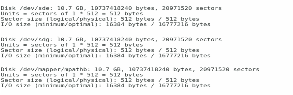
|
|
NOTE: If no disk is found, execute the echo 1 > /sys/class/fc_host/hostnum/issue_lip command to manually refresh fc_host, where hostnum indicates the FC port number under the OS. |
2. After multiple paths are configured, execute the fdisk -l command again to view a newly added mpatha volume, indicating that the system can access the virtual volume through multiple paths, as shown in Figure 54.
Figure 54 Viewing the mpatha volume

Example: Configuring FC pass-through modules (connecting FC pass-through module to FC switch)
Network requirement
As shown in Figure 55, the blade server and FC pass-through modules are installed in the B16000 blade server chassis. The blade server is installed in slot 12, two FC switch modules are installed in slot 3 and slot 6, and the mezzanine card is installed in the mezzanine card slot 3 of the blade server. The FC 1/1/12 port of each of the two FC switch modules is connected to an FC switch, and the FC switch is connected to the FC storage device through the 1:0:1 port.
In this example, the following devices and modules are used: blade server (H3C UniServer B5700 G3), mezzanine card (NIC-FC730i-Mb-2P, "FC730i"), Ethernet pass-through module (BT716F), switch (Brocade), and FC storage device (H3C CF8840 from the HPE 3Par StoreServ family).
The following requirements are expected to be met:
The OS on the blade server can mount storage volumes on the 3Par, and you can still access data on the 3Par through OS on the blade server when any interconnect module fails.
Figure 55 Network diagram between FC pass-through modules and FC switches
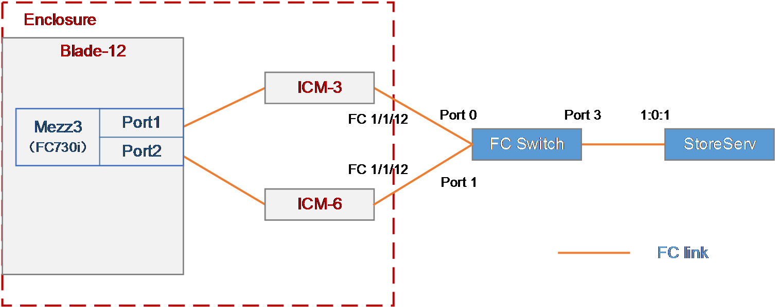
Analysis
· Before configuration, you need to query the correspondence between the mezzanine card, the external port of the pass-through module, and the mezzanine card port displayed under the OS, to ensure that the correct ports are configured and facilitate the verification after configuration.
· To mount a 3Par storage volume under the OS, build an FC link between the blade server and the 3Par storage, and create a storage volume on the 3Par storage. Then, the OS can automatically identify the storage volume.
· To ensure service continuity when any interconnect module fails, you need to configure the multilink function under the OS to improve network reliability.
Configuration precautions
· After mounting the storage volumes and replacing existing storage volumes on the 3Par with new ones, reboot the OS of the blade server to identify the new volumes.
· Make sure that the blade server's OS can recognize the FC730i network adapter correctly. If it cannot, install the network adapter driver. For details, see FC730i Mezzanine Card Module User Guide.
Configuration procedure
Querying port information
Query the connection relation between the internal ports of mezzanine cards and interconnect modules according to "Querying port relations."
It can be seen that the FC 1/1/12 ports of the interconnect module 3 and interconnect module 6 are used in this example.
Configuring the mezzanine card
In this example, there is no need to configure the mezzanine card.
Configuring the Brocade switch
In this example, the Brocade switch uses the default settings. Ensure that Port 0, Port 1, and Port 3 reside in the same FC zone.
Configuring 3Par storage
See "Configuring 3Par storage" for the process of configuring the 3Par storage server.
Configuring the OS
|
|
NOTE: · The following information provides the procedure for configuring multipath under Red Hat 7.5. Multipath can realize the loading balancing and reliability of the traffic between hosts and storage devices. · Before configuration, ensure that the OS has installed the multipath tool, a built-in tool of most Linux systems. |
1. Execute the following commands in turn to load the multipath server, set the polling mode, enable the multipath service, and format the path.
# modprobe dm-multipath
# modprobe dm-round-robin
# service multipathd start
# multipath –v2
|
|
NOTE: If it is prompted that the multipath.conf file does not exist under the Red Hat operating system, you can copy the file from another location and deliver it again, as shown in Figure 56. |
Figure 56 Handling the case when the multipath.conf file does not exist

2. Execute the following command to reboot the multipath server.
# systemctl restart multipathd.service
3. Run the following command to view the multipath link status, and you can see that the two ports are in the active state, as shown in Figure 57.
# multipath –ll
Figure 57 Viewing the multipath link status

Verifying the configuration
1. Execute the fdisk -l command under the OS to view the two virtual volumes identified by the host, as shown in Figure 58.
Figure 58 Identifying the virtual volumes

|
|
NOTE: If no disk is found, execute the echo 1 > /sys/class/fc_host/hostnum/issue_lip command to manually refresh fc_host, where hostnum indicates the FC port number under the OS. |
2. After multiple paths are configured, execute the fdisk -l command again to view the new mpatha volume, indicating that the system can access virtual volumes through multiple paths, as shown in Figure 59.
Figure 59 Viewing the mpatha volume

Common operations
Querying port relations
Query the interface connection between mezzanine cards and interconnect modules
Please use the H3C networking query tool on the official website to view the port connection relation between mezzanine cards and interconnect modules.
Query the MAC address or WWN number of the mezzanine card.
Log in to the OM Web page and click Blade Server Management/Target Blade Server/Port Mapping to view the port MAC address of the Ethernet mezzanine card and the port WWN number of the FC mezzanine card.
Querying the port correspondence between the network adapter and the mezzanine card under the OS
1. To view the MAC addresses of all network adapters, execute the ipconfig -all command in Windows and execute the ifconfig command in Linux.
2. According to the MAC addresses or WWNs queried above, you can learn the correspondence between the ports on the network adapter and the mezzanine card under the OS.
Configuring multipath and adding network disks on Windows Server
Procedures
|
|
NOTE: The following information provides the procedure for configuring multipath and adding network disks on Windows Server. The Windows Server 2016 is used as an example. |
1. The multipath function on the Windows OS is disabled by default. You can install and enable it through the following steps.
a. As shown in Figure 60, in the OS, click Server Manager > Dashboard > 2 Add roles and features to open the Add Roles and Features Wizard configuration screen.
Figure 60 Add roles and features
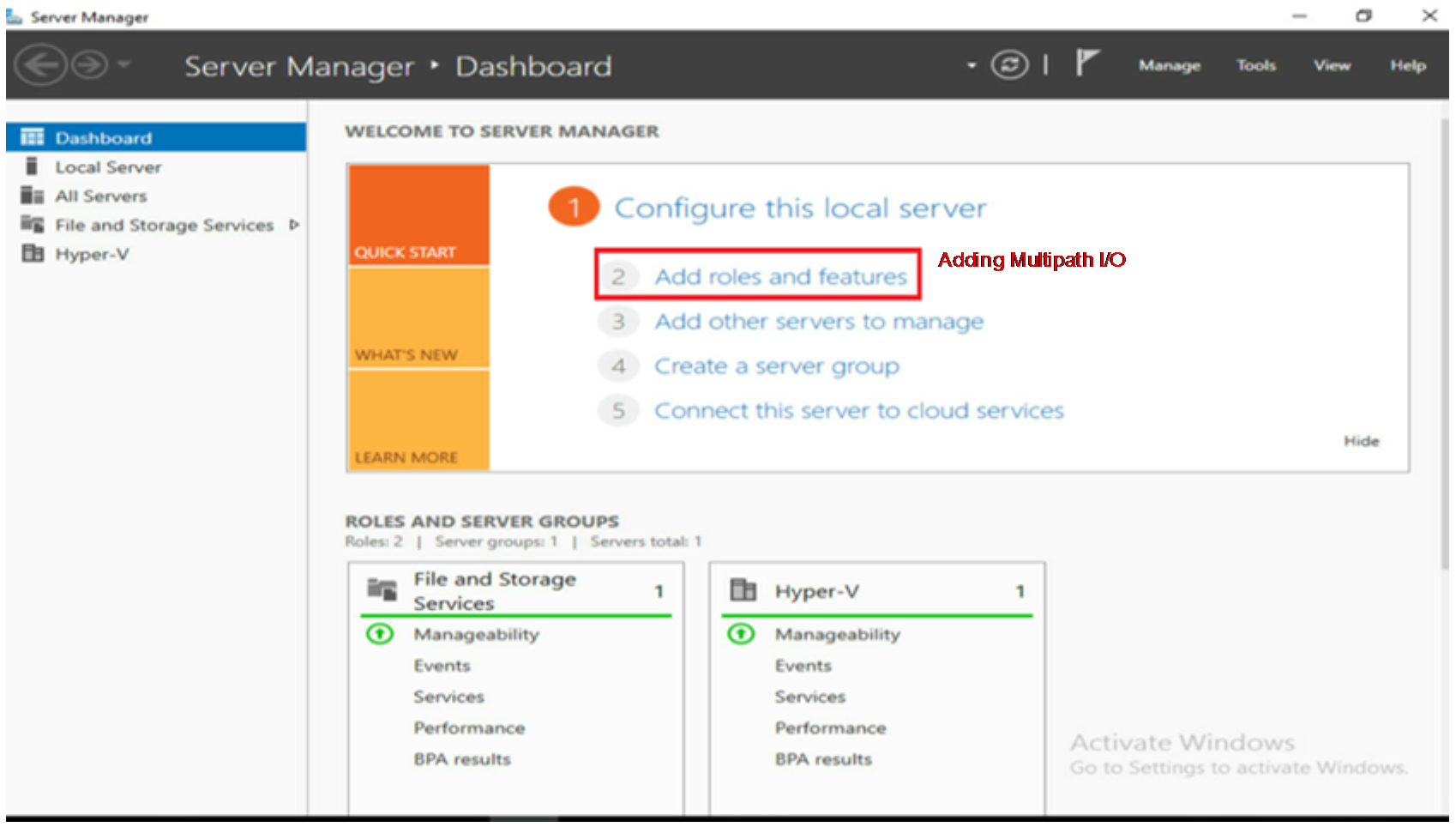
b. In the pop-up wizard, select the default value and click Next until the screen as shown in Figure 61 appears. In the screen, select Multipath I/O and click Next.
Figure 61 Selecting Multipath I/O
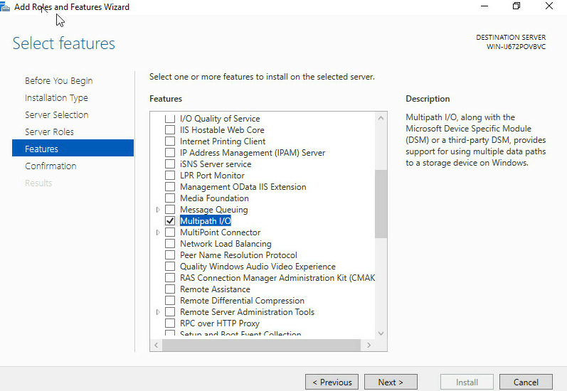
c. As shown in Figure 62, select Restart the destination server automatically if required and click Install to start the installation.
Figure 62 Starting the installation
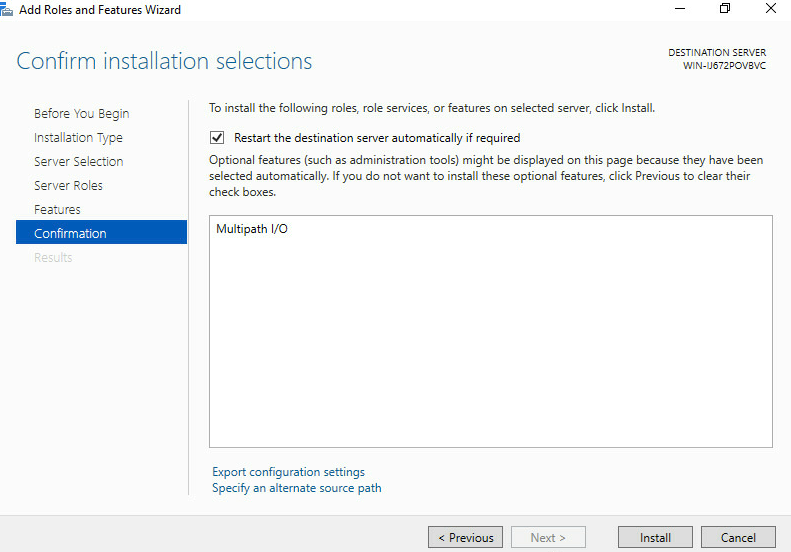
d. As shown in Figure 63, when the installation is complete, click Close to close the screen.
Figure 63 Installation completed
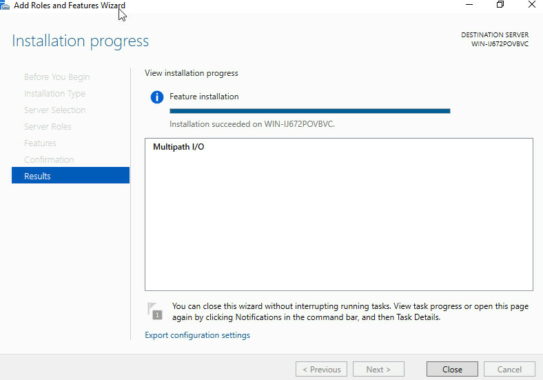
2. Set the Multipath I/O (MPIO) and add a storage array.
a. As shown in Figure 64, in the Server Manager screen, select Tools > MPIO in the upper right corner to open the multipath setting screen.
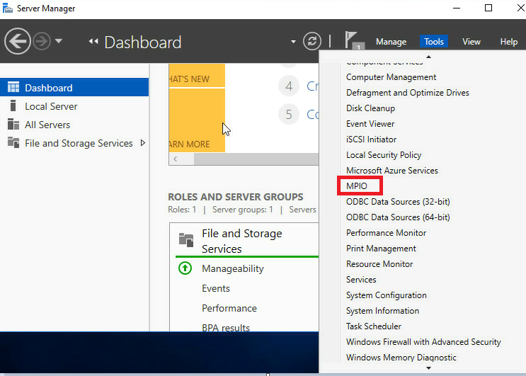
b. As shown in Figure 65, in the Discover Multi-Paths tab, select 3PardataW, click Add, and then click OK. Then, reboot the server.
Figure 65 Discovering multi-paths
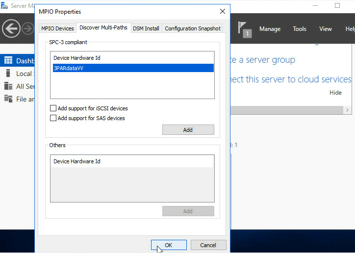
3. Configure the MPIO policy.
a. As shown in Figure 66, after
rebooting, right-click the ![]() button in the lower left corner of the screen and select Disk Management.
button in the lower left corner of the screen and select Disk Management.
Figure 66 Opening Disk Management
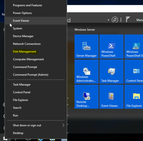
b. As shown in Figure 67, locate the storage volume mounted from the 3Par, right-click it and select Properties.
Figure 67 Selecting the network storage volume
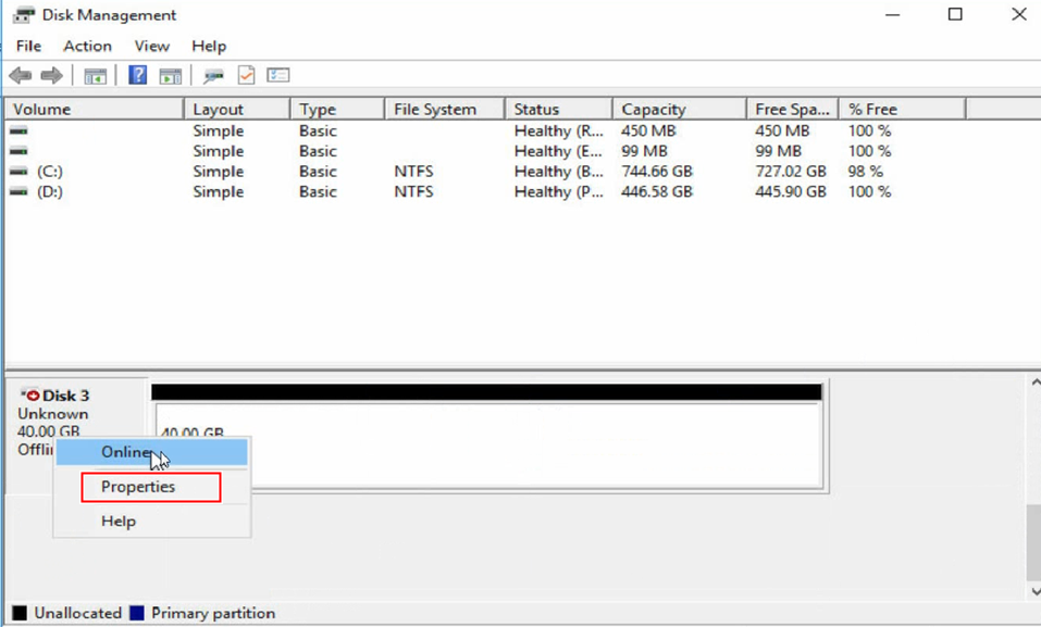
c. As shown in Figure 68, select the MPIO tab, and select the option in Select the MPIO policy. In this example, Fail Over Only is selected. It is an active/standby mode that enables the traffic to be automatically switched to another path when one path fails.
Figure 68 Setting the MPIO policy
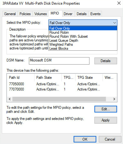
d. As shown in Figure 69, select the Detail tab, select Path Verify Enabled in the pop-up dialog box, and click OK.
Figure 69 Starting path verification
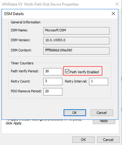
e. As shown in Figure 70, select one of the two active paths, and modify Path State to Standby. You can also select one path in Figure 68, click Edit, select Standby in Path State, and click OK.
Figure 70 Modifying the path state
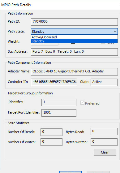
f. As shown in Figure 71, click OK to complete the configuration.
Figure 71 Configuration completed
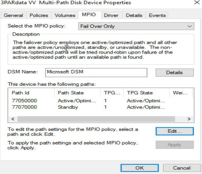
4. Adding a network disk
a. As shown in Figure 72, right-click the Windows icon in the lower left corner of the system, open Disk Management, right-click the newly recognized disk, and select Online to bring the disk online.
Figure 72 Bringing the disk online
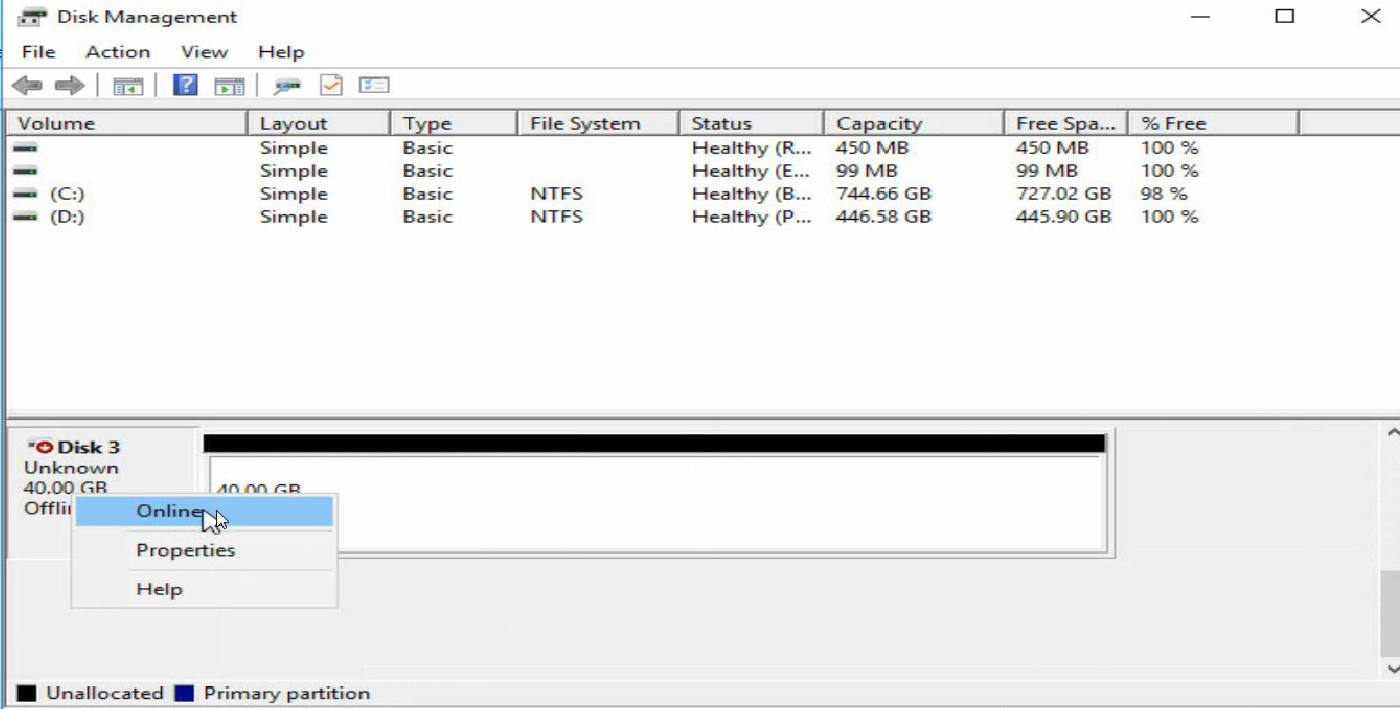
b. As shown in Figure 73, right-click the disk name again and select Initialize Disk to initialize the disk.
Figure 73 Initializing the disk
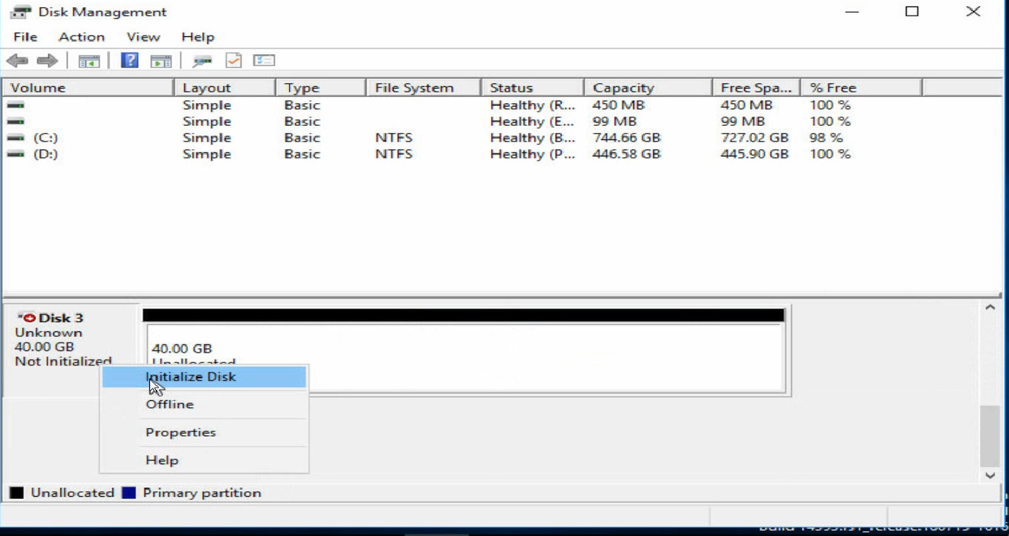
c. As shown in Figure 74, right-click the Unallocated area of the disk and follow the prompts to create new volumes.
Figure 74 Creating new disk volumes
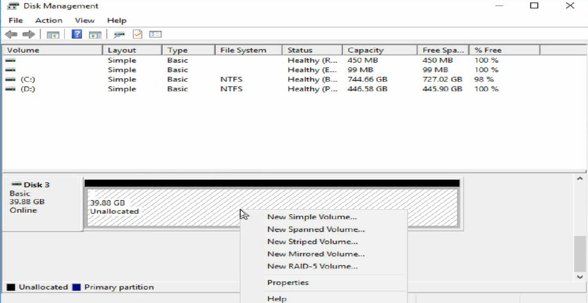
d. Then, the disk status is as shown in Figure 75.
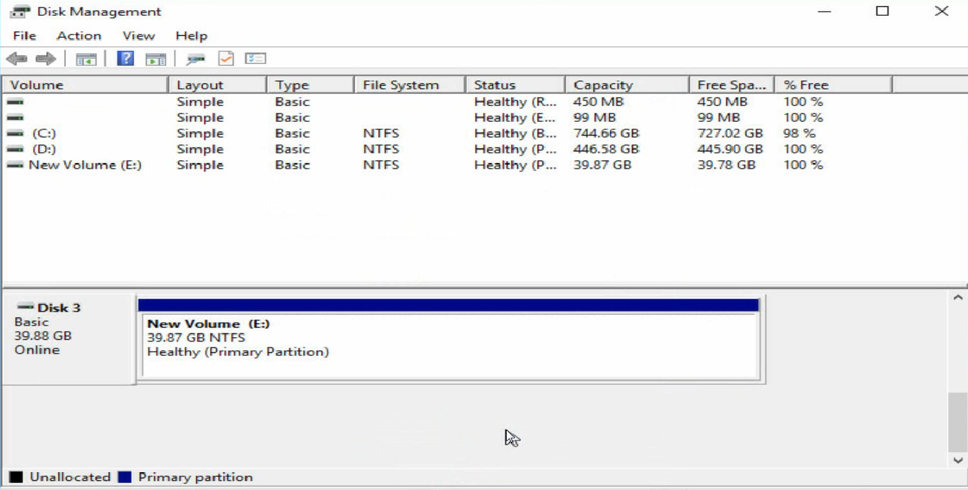
Verifying the configuration
1. Execute the display npv login command on the aggregation interconnect module to view the registration information about the node device connected to the downlink port of the aggregation interconnect module and the mapped uplink port.
<H3C> display npv login
Server External
Interface VSAN FCID Node WWN Port WWN Interface
Vfc1 1 0x021101 10:00:38:97:d6:e2:5e:ee 20:00:38:97:d6:e2:5e:ee Fc1/1/1
2. View the multipath information under the OS.
As shown in Figure 76, open the Windows PowerShell command line screen and execute the mpclaim –s –d 0 command. You can see the information about the two paths. One is in the Active state, and the other is in the Standby state.
Figure 76 Checking the MPIO information
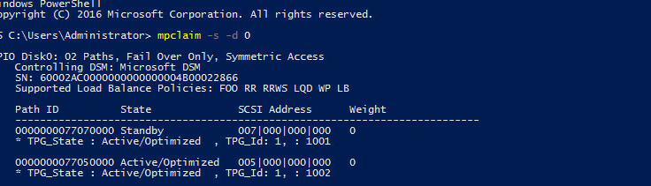
Note that Device ID in this example is 0. It may be another value. To view disk ID, you can right-click the newly mounted disk in Disk Management, select Properties > Detail, and select Physical Device Object name in the Property drop-down menu. MPIODisk3 shown in Figure 77 indicates that the device ID is 3.
Figure 77 Viewing the device ID
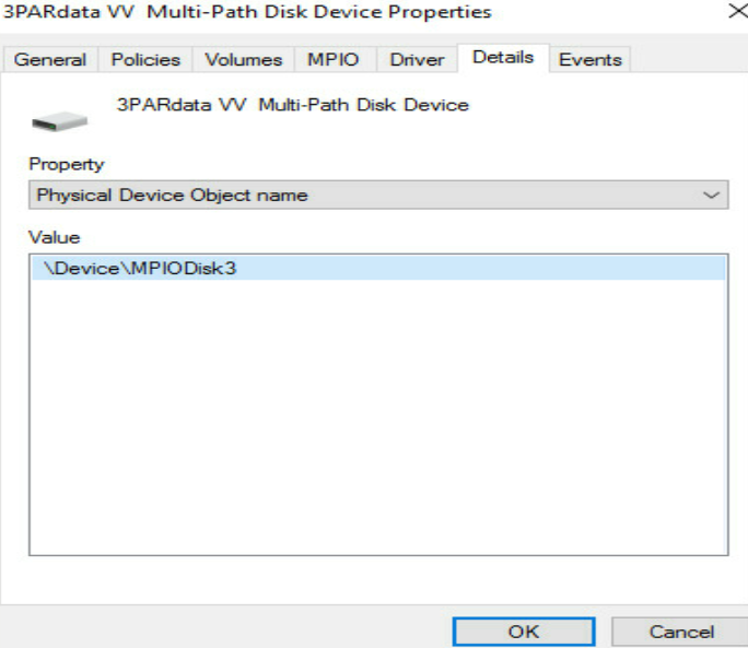
3. Identify the network disk.
As shown in Figure 78, open This PC to view the new partition.
Figure 78 Identifying the network disk
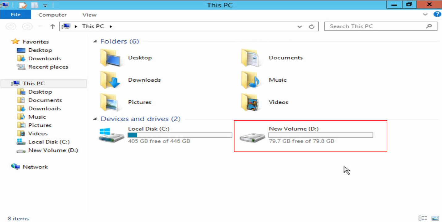
Configuring 3Par storage
1. As shown in Figure 79, log in to the 3Par storage with the default username (3paradm) and the default password (3pardata).
Figure 79 Logging in to the 3Par storage
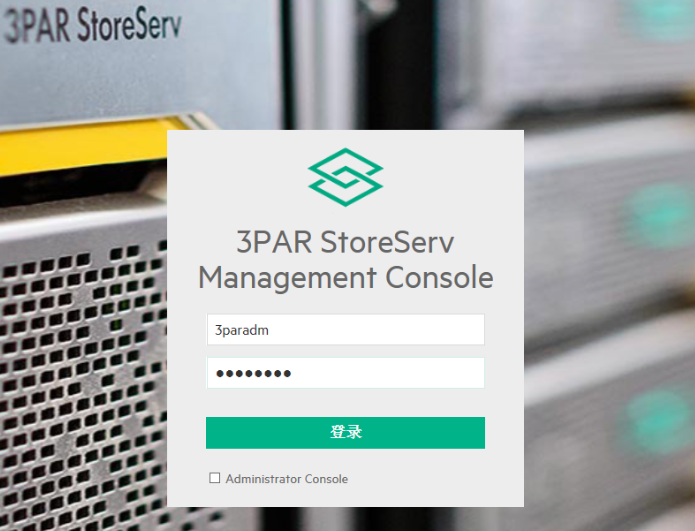
2. Creating a host
a. Click the 3Par StoreServ drop-down arrow and select Host.
b. Set the basic information about the host, including host name, OS, etc. Then, click the Create button at the bottom of the screen to create the host and then add FC.
c. Click the Continue button In the pop-up dialog box to continue creating the host.
3. Creating a virtual volume
a. Click the 3Par StoreServ drop-down arrow and select Virtual Machine.
b. Set the parameters of the virtual volume, including volume name, CPG, size, etc. Then, click the Create button at the bottom of the screen.
4. Exporting the virtual volume to the host
a. In the Host screen, select the host you created, and then click Action > Edit in the upper right corner of the screen.
b. In the pop-up page, click the Add button, select the host just created, and click Export.
c. You can see that the virtual machine has been exported in the host information page.
5. Add an FC path
a. In the Host screen, click Operation > Edit in the upper right corner and select Add FC. You can view the two FC paths identified by 3Par and the WWNs of the corresponding two ports on the mezzanine card.
b. Click the Add button and add the FC paths to the list.
c. You can view the added FC paths in the host information page. The configuration of the 3Par storage is complete.
Compatibility between the storage of different models and the blade server
Compatibility between the storage of different models and the blade server
The B16000 blade server chassis is compatible with the storage of the following models:
· Primera series storage
· Nimble series storage
· 3Par series storage
· MSA series storage
The compatibility relationship between networking hardware and storage in B16000 is shown in the following table:
Table 5 Hardware compatibility of Primera series storage
|
Primera series storage |
|||
|
Network type |
NIC model |
Interconnect module |
Transceiver module |
|
FC |
FC680i FC730i |
BX608FE |
16 Gb FC transceiver module |
|
FCoE |
ETH521i ETH522i |
BX1020EF |
16 Gb FC transceiver module 32 Gb FC transceiver module |
|
BX720EF |
16 Gb FC transceiver module |
||
|
ETH682i |
BX1020EF |
16 Gb FC transceiver module 32 Gb FC transceiver module |
|
Table 6 Hardware compatibility of Nimble series storage
|
Nimble series storage |
|||
|
Network type |
NIC model |
Interconnect module |
Transceiver module |
|
FC |
FC680i FC730i |
BX608FE |
16 Gb FC transceiver module |
|
FCoE |
ETH521i ETH522i |
BX1020EF BX720EF |
|
|
ETH682i |
BX1020EF |
||
Table 7 Hardware compatibility of 3Par series storage
|
3Par series storage |
|||
|
Network type |
NIC model |
Interconnect module |
Transceiver module |
|
FC |
FC680i FC730i |
BX608FE |
16 Gb FC transceiver module |
|
FCoE |
ETH521i ETH522i |
BX1020EF BX720EF |
|
|
ETH682i |
BX1020EF |
||
|
iSCSI |
ETH521i ETH522i |
BX1020EF BX720EF BX720E |
10 Gb Ethernet transceiver module |
|
ETH682i |
BX1020EF |
||
Table 8 Hardware compatibility of MSA series storage
|
MSA series storage |
|||
|
Network type |
NIC model |
Interconnect module |
Transceiver module |
|
FC |
FC680i FC730i |
BX608FE |
16 Gb FC transceiver module |
|
FCoE |
ETH521i ETH522i |
BX1020EF BX720EF |
|
|
ETH682i |
BX1020EF |
||
|
iSCSI |
ETH521i ETH522i |
BX1020EF BX720EF BX720E |
10 Gb Ethernet transceiver module |
|
ETH682i |
BX1020EF |
||
Recommended configuration
The recommended configuration varies with different modes. Here we use 3Par storage as an example.
FCF mode: NIC-ETH682i-Mb-2*25G---BX1020EF---8G/16G transceiver module---3Par storage
NPV mode: NIC-ETH682i-Mb-2*25G---BX1020EF----8G/16G transceiver module--- FC switch---3Par storage
