- Table of Contents
-
- H3C UniServer B16000 Blade Server Configuration Examples-6W101
- 01-FC and FCoE Services Configuration Examples
- 02-Ethernet Services Configuration Examples
- 03-Virtual Management Network Configuration Examples
- 04-Shared Storage Configuration Examples
- 05-VC Configuration Examples
- 06-Chassis Profile Configuration Examples
- 07-IB Service Configuration Examples
- 08-Blade Server FIST Configuration Examples
- Related Documents
-
| Title | Size | Download |
|---|---|---|
| 07-IB Service Configuration Examples | 2.95 MB |
Contents
Example: Configuring single-chassis IB networking
Hardware configuration analysis
Software configuration analysis
Configuring interconnect modules
Configuring the operating system of the blade server
Verifying network connectivity
Example: Configuring double-chassis IB direct connect networking
Hardware configuration analysis
Software configuration analysis
Configuring the interconnect module
Configuring the operating system of the blade server
Verifying network connectivity
Install IB network adapter driver
Introduction
The following information provides examples for configuring InfiniBand (IB) services for the H3C UniServer B16000 blade server chassis.
Hardware compatibility
Table 1 Hardware compatibility
|
Configuration example |
Compatible hardware models |
|||
|
Network adapter |
Interconnect module |
External switch |
Back-end storage |
|
|
Configuring single-chassis IB networking |
IB1040i |
BX1020B |
N/A |
N/A |
|
Configuring double-chassis IB direct connect networking |
IB1040i |
BX1020B |
N/A |
N/A |
Prerequisites
The configuration examples were created and verified in a lab environment, and all the devices were started with the factory default configuration. When you are working on a live network, make sure you understand the potential impact of every command on your network.
The following information is provided based on the assumption that you have basic knowledge of IB services, H3C blade servers, and interconnect modules.
The following information mainly describes configuration on the blade server chassis. As a best practice, configure external network settings as needed.
Example: Configuring single-chassis IB networking
Network configuration
As shown in Figure 1, B16000 blade server chassis is installed with three blade servers and one interconnect module. In the front part of the chassis, three blade servers are installed at slots 1, 3, and 5, respectively. In the rear part of the chassis, the interconnect module is installed at slot 1. The Mezz network adapter is always installed at slot Mezz 1 of a server.
In this example, the blade server H3C UniServer B5700 G3 adopts Red Hat 7.5 operating system; the Mezz network adapter is IB1040i-Mb-2*100G (hereinafter referred to as IB1040i); and interconnect module uses BX1020B.
The following requirements are expected to be met:
Run Subnet Manager (hereinafter referred to as SM) on Blade 5. Manage the entire IB cluster through SM (IB cluster refers to the collection of all manageable IB Mezz network adapters and IB interconnect modules in the network), and realize the interconnection between blade servers through the IB network, with the data interaction latency as low as possible.
Analysis
Hardware configuration analysis
If the batch script command is executed when IB devices are being deployed, blade servers can be installed on the same side of the chassis. In this way, all IB Mezz network adapters can be connected with the IB interconnect module through port 1, thus simplifying the script.
Software configuration analysis
· The host names of blade servers are predetermined by default. It is advised to modify the host names so that specific blade servers can be identified in later steps. In this example, the server with the management feature is named "mgnt", and the other servers are named "testnodeX0Y" where "X" represents the chassis number and "Y" represents the blade server slot number, for example, "testnode101" represents Blade 1 in Enclosure 1.
· To ensure the shortest data interaction latency between servers, it is advised to change the routing algorithm according to the network topology. In this case, it is advised to adopt the ftree algorithm to achieve load balancing of bandwidth and avoid deadlock.
Software versions used
This configuration example was created and verified on 16.25.8000 of the IB1040i Mezz network adapter and on 27.2000.1600 of the BX1020B interconnect module.
Procedures
Configuring interconnect modules
The IB interconnect module has no management capabilities and is ready for use once the operating system on the blade server has been configured. In this example, there are no other special requirements for the interconnect module, so it only needs to be installed in place.
Configuring the operating system of the blade server
Prerequisites
1. Modify the host names of all blade servers to make it easier to identify specific blade servers in the system. As shown in Figure 2, execute the hostnamectl --static set-hostname <hostname> command to set host name. The host name takes effect after the system is restarted. In this example, the server with the management feature is named "mgnt", the other servers are named "testnode101" and "testnode102" and so on.
Figure 2 Editing the host name
![]()
2. For details about updating the IB1040i Mezz network adapter driver for all blade servers, see "Install IB network adapter driver."
3. For details about installing the MFT tool on the SM node (Blade 5), see "Install the MFT tool."
Configuring OpenSM
The SM (OpenSM) is integrated in the IB Mezz network adapter driver. After the driver is installed, OpenSM also has been installed by default. Configure OpenSM as follows.
1. As shown in Figure 3, execute the /etc/init.d/opensmd start command to enable OpenSM.
![]()
2. As shown in Figure 4, execute the opensm --create-config /etc/opensm/opensm.conf command to create the opensm.conf configuration file. This file is used to modify the routing algorithm of SM.
Figure 4 Creating the opensm.conf configuration file
![]()
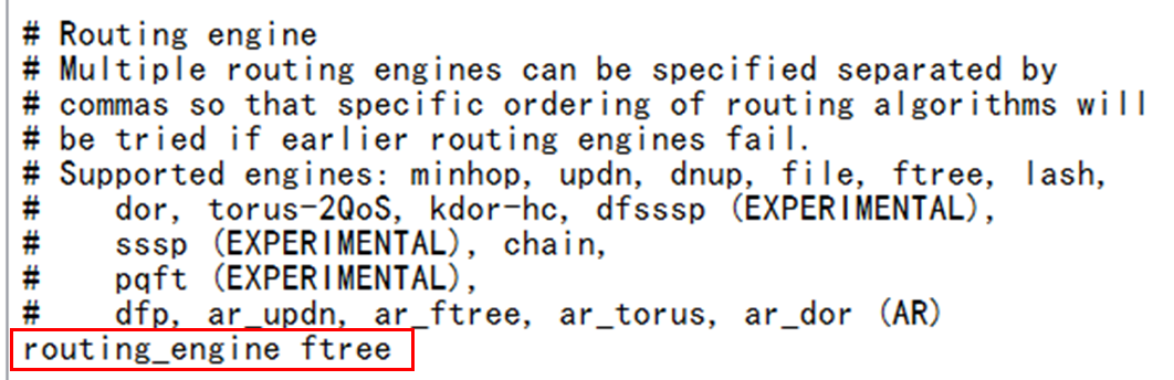
3. The minhop routing algorithm is used for OpenSM by default. When the network adopts the fat-tree topology, it is advised to modify it to the ftree routing algorithm. Modify the routing algorithm as follows:
a. Execute the vi opensm.conf command to edit the configuration file.
b. Find the routing_engine field and add the ftree routing algorithm after it, as shown in Figure 5.
c. Enter wq, save it and exit.
Figure 5 Modifying the routing algorithm

4. Execute the /etc/init.d/opensm restart command to complete configuration and restart the SM service.
5. Execute the chkconfig opensmd on command to make SM automatic starting upon boot.
Figure 6 Making SM automatic starting upon boot
![]()
Configuring the OpenSM cluster
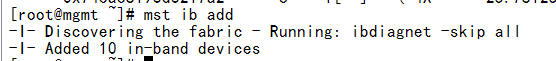
1. As shown in Figure 7, after the SM is successfully set up, execute the mst ib add command to automatically add all IB devices in the cluster to the SM for unified management.
Figure 7 Adding IB devices into the cluster

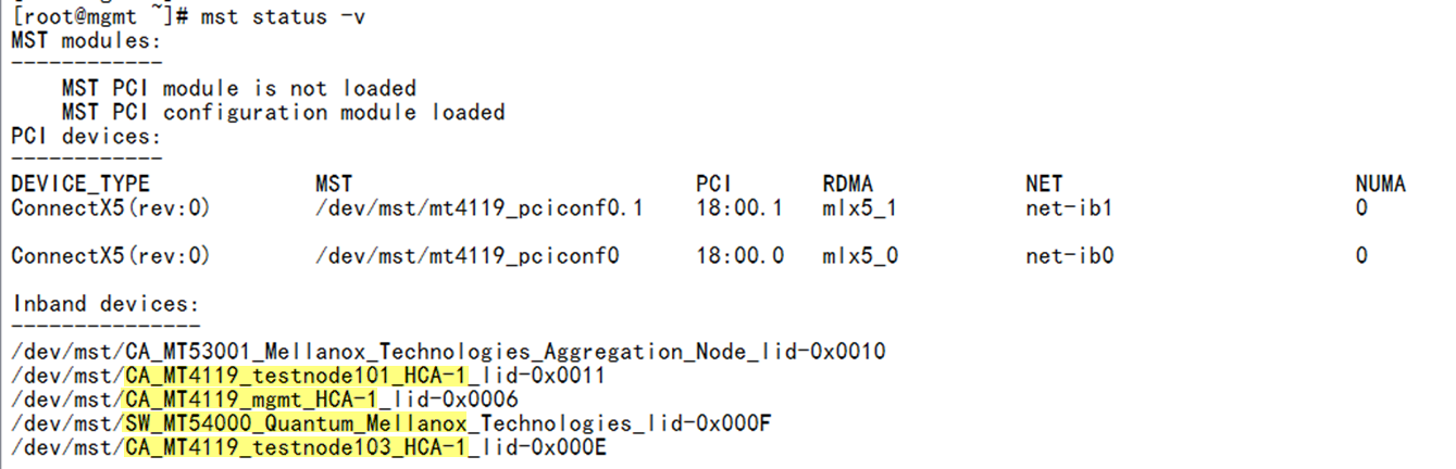
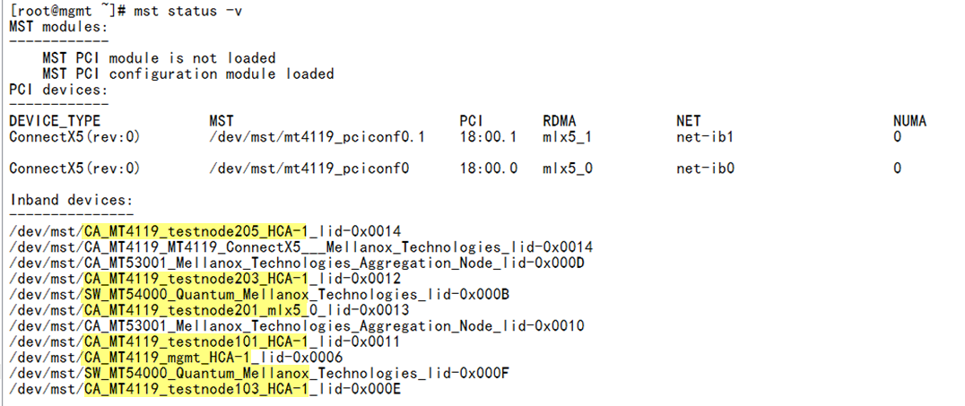
2. As shown in Figure 8, execute the mst status –v command to query all IB devices (IB switch module and IB Mezz network adapter) in the current cluster and ensure that all IB devices have been added to the cluster.
Configuring IB network
To enable mutual communication between blade servers, configure the IP addresses for the IB ports of servers, which is configured in the same way as the IP address of the Ethernet port, as shown below.
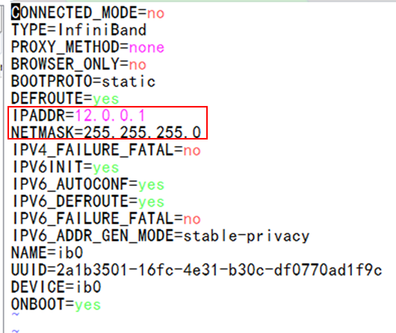
1. As shown in Figure 9, in the /etc/sysconfig/network-scripts/ directory of the SM node, execute the vi ifcfg-ib0 command to edit the network configuration file for the IB port. You can configure the IP address and subnet mask, and then save them and exit.
Figure 9 Setting parameters for IB network

2. Execute the systemctl restart network.service command to restart the network service.
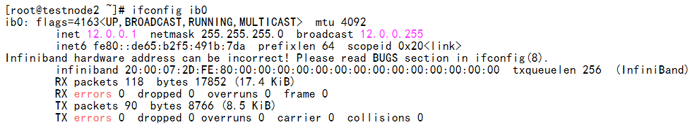
3. Execute the ifconfig ib0 command to confirm details of the IB port, as shown in Figure 10.
Figure 10 Viewing the IB port state

4. Configure the IB network for the other two blade servers by referring to the above steps.
Verifying the configuration
Verifying network connectivity
Examining the IB port state and rate
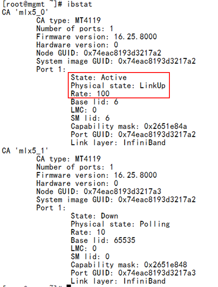
Execute the ibstat command on the SM node to check the IB port state and rate. As shown in Figure 11, you can see that the state of the mlx5_0 port of the IB network adapter (port 1 in Figure 1) is active and the negotiated rate is 100 Gpbs.
Figure 11 Viewing the state of the IB Mezz network adapter port
Verifying the network topology
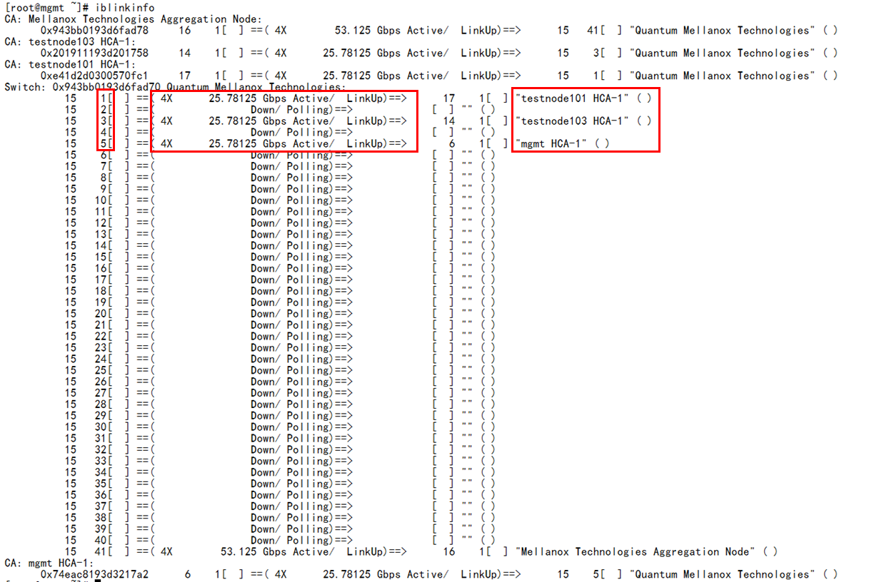
Execute the iblinkinfo command on the SM node to check whether the network topology is consistent with the network configuration. As shown in Figure 12, you can see the port connection information of all blade servers (CA) and switch modules (switches), including the slot No. of blade servers, port rate and state, and names of peer devices. For detailed description of this command, see BX1020B IB Switch Module Solution.
Figure 12 Verifying the network topology
Verifying the physical link state
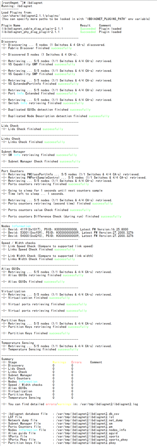
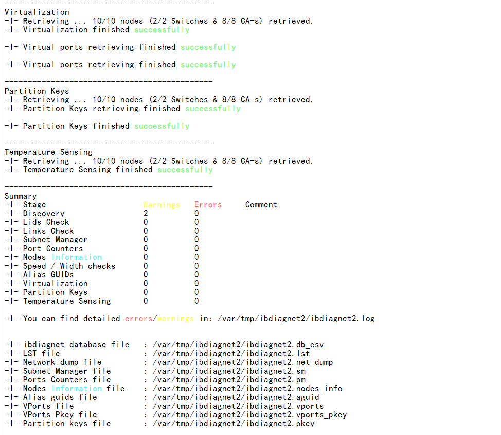
Execute the ibdiagnet command at SM nodes to check the health state of the physical fiber link. In this way, you can check whether the fiber is damaged or the connection is unstable. As shown in Figure 13, if the values of Errors and Warnings are 0, it indicates that the physical link is normal; if there is an error message, you can view the log in /var/tmp/ibdiagnet/.
Figure 13 Verifying the physical fiber link
Verifying network bandwidth
After completing the network link check, perform the following steps to check the IB network bandwidth between any two blade servers.
1. Select any two blade servers, with one serving as the server side and the other as the client side.
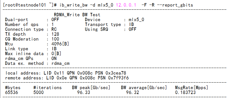
2. Execute the ib_write_bw -d mlx5_0 -F -R --report_gbits --run_infinitely command at the server side.
3. Execute the ib_write_bw -d mlx5_0 ip_address -F -R --report_gbits --run_infinitely command at the client side. ip_ address represents the system IP address at the server side.
4. As shown in Figure 14, you can see that the measured bandwidth rate reaches more than 96% of the maximum bandwidth, which indicates that the performance is normal.
Figure 14 Verifying network bandwidth
Example: Configuring double-chassis IB direct connect networking
Network requirement:
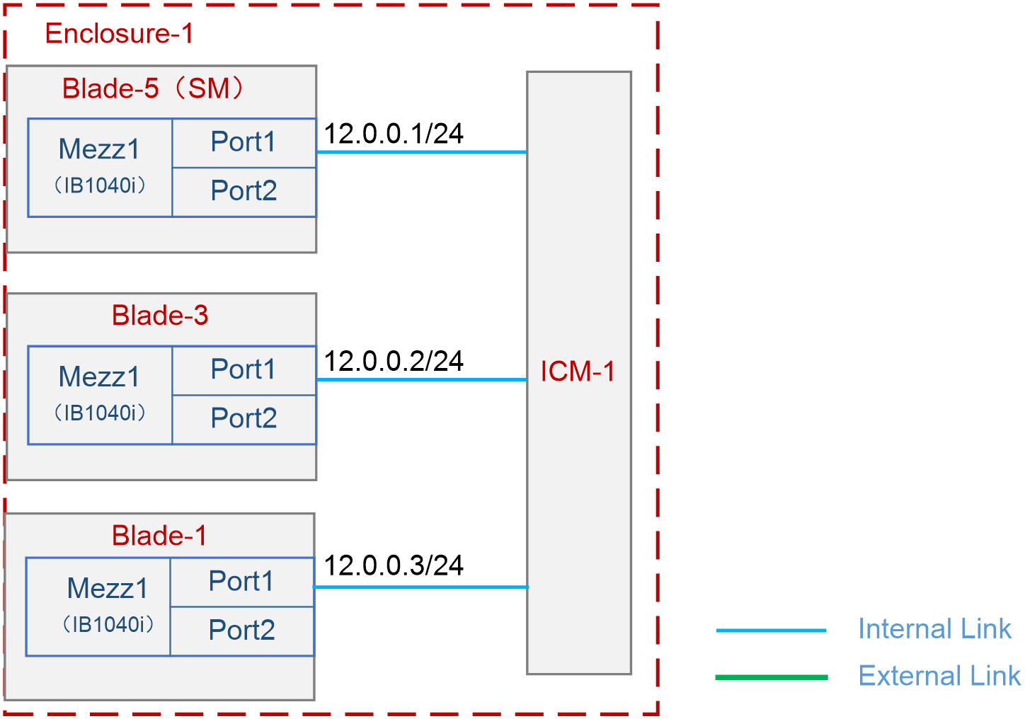
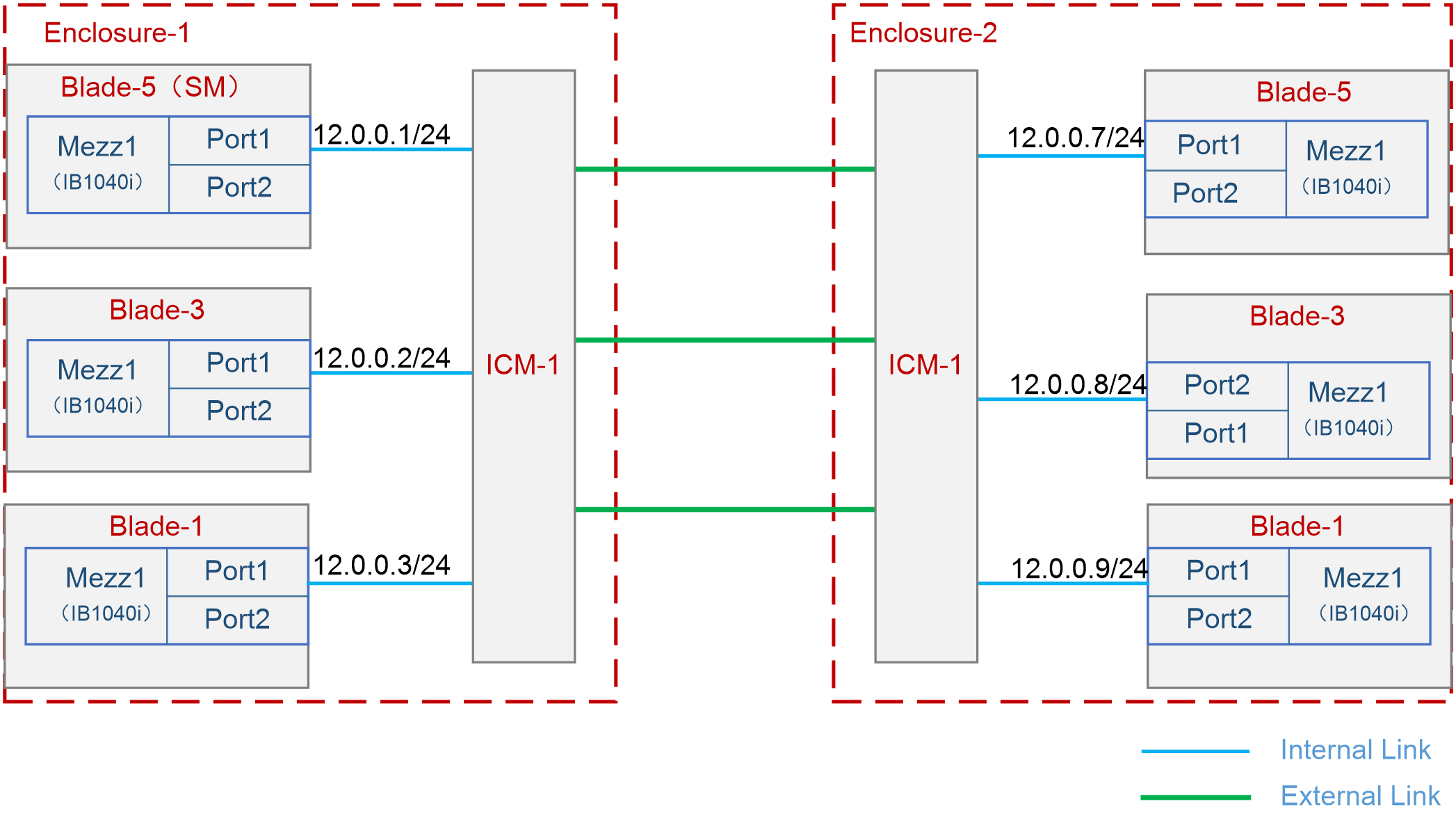
As shown in Figure 15, two B16000 blade server chassis are interconnected through IB link. Three blade servers and one interconnect module are installed in each chassis. In the front part of the chassis, three blade servers are installed at slots 1, 3, and 5. In the rear part of the chassis, the interconnect module is installed at slot 1. The Mezz network adapter is always installed at slot Mezz 1 of a server. The interconnect module in each chassis is interconnected through its external port.
In this example, the blade server H3C UniServer B5700 G3 adopts Red Hat 7.5 operating system; the Mezz network adapter is IB1040i-Mb-2*100G (hereinafter referred to as IB1040i); and interconnect module uses BX1020B.
The following requirements are expected to be met:
Run SM on Blade 5 in Enclosure 1. Manage the entire IB cluster through SM (IB cluster refers to the collection of all manageable IB Mezz network adapters and IB interconnect modules in the network), and realize the interconnection between blade servers through the IB network, with the data interaction latency as low as possible.
Figure 15 Configuring double-chassis IB direct connect networking
Analysis
Hardware configuration analysis
· The IB interconnect module provides several external ports and there is no difference between them. The chassis can interconnect with other IB devices using any external port. In this example, three blade servers are installed inside each chassis, so there are three external ports available for connection between interconnect modules to ensure sufficient uplink bandwidth.
· If the batch script command is executed when IB devices are being deployed, blade servers can be installed on the same side of the chassis. In this way, all IB Mezz network adapters can be connected with the IB interconnect module through port 1, thus simplifying the script.
Software configuration analysis
· The host names of blade servers are predetermined by default. It is advised to modify the host names so that specific blade servers can be identified in later steps. In this example, the server with the management feature is named "mgnt", the other servers are named "testnode101" and "testnode102" and so on.
· To ensure the shortest data interaction latency between servers, it is advised to change the routing algorithm according to the network topology. In this case, it is advised to adopt the ftree algorithm to achieve load balancing of bandwidth and avoid deadlock.
Software versions used
This configuration example was created and verified on 16.25.8000 of the IB1040i Mezz network adapter and on 27.2000.1600 of the BX1020B interconnect module.
Configuration procedure
Configuring the interconnect module
The IB interconnect module has no management capabilities and is ready for use once the operating system on the blade server has been configured. In this example, there are no other special requirements for the interconnect module, so it only needs to be installed in place.
Configuring the operating system of the blade server
Preparation
1. Modify the host names of all blade servers to make it easier to identify specific blade servers in the system. As shown in Figure 16, execute the hostnamectl --static set-hostname <hostname> command to set the host name. The host name takes effect after the system is restarted. In this example, the server with the management feature is named "mgnt," and the other servers are named "testnodeX0Y," where "X" represents the chassis number and "Y" represents the blade server slot number, for example, "testnode101" represents Blade 1 in Enclosure 1.
Figure 16 Editing the host name
![]()
2. For details about updating the IB1040i Mezz network adapter driver for all blade servers, see "Install IB network adapter driver."
3. For details about installing the MFT tool on the SM node (Blade 5), see "Install the MFT tool."
Configuring OpenSM
The SM (OpenSM) is integrated in the IB Mezz network adapter driver. After the driver is installed, OpenSM also has been installed by default. Configure OpenSM as follows:
1. As shown in Figure 17, execute the /etc/init.d/opensmd start command to enable OpenSM.
![]()
2. As shown in Figure 18, execute the opensm --create-config /etc/opensm/opensm.conf command to create the opensm.conf configuration file. This file is used to modify the routing algorithm of SM.
Figure 18 Creating the opensm.conf configuration file
![]()
3. The minhop routing algorithm is used for OpenSM by default. When the network adopts the fat-tree topology, it is advised to modify it to the ftree routing algorithm. Modify the routing algorithm as follows:
a. Execute the vi opensm.conf command to edit the configuration file.
b. Find the routing_engine field and add the ftree routing algorithm after it, as shown in Figure 19.
c. Enter wq, save it and exit.
Figure 19 Modifying the routing algorithm
4. Execute the /etc/init.d/opensm restart command to complete configuration and restart the SM service.
5. Execute the chkconfig opensmd on command to make SM automatic starting upon boot.
Figure 20 Making SM automatic starting upon boot
![]()
Configuring the OpenSM cluster
1. As shown in Figure 21, after the SM is successfully set up, execute the mst ib add command to automatically add all IB devices in the cluster to the SM for unified management.
Figure 21 Adding IB devices into the cluster
2. As shown in Figure 22, execute the mst status –v command to query all IB devices (IB switch module and IB Mezz network adapter) in the current cluster and ensure that all IB devices have been added to the cluster.
Configuring IB network
To enable mutual communication between blade servers, configure the IP addresses for the IB ports of servers, which is configured in the same way as the IP address of the Ethernet port, as shown below.
1. As shown in Figure 9, in the /etc/sysconfig/network-scripts/ directory of the SM node, execute the vi ifcfg-ib0 command to edit the network configuration file for the IB port. You can configure the IP address and subnet mask, and then save them and exit.
Figure 23 Setting parameters for IB network
2. Execute the systemctl restart network.service command to restart the network service.
3. Execute the ifconfig ib0 command to confirm details of the IB port, as shown in Figure 24.
Figure 24 Viewing the IB port state
4. Configure the IB network for the other five blade servers by referring to the above steps.
Verifying the configuration
Verifying network connectivity
Examining the IB port state and rate
Execute the ibstat command on the SM node to check the IB port state and rate. As shown in Figure 25, you can see that the state of the mlx5_0 port of the IB network adapter (port 1 in Figure 1) is active and the negotiated rate is 100 Gpbs.
Figure 25 Viewing the state of the IB Mezz network adapter port

Verifying the network topology
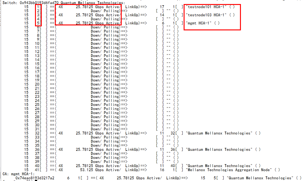
Execute the iblinkinfo command on the SM node to check whether the network topology is consistent with the network configuration. As shown in Figure 26 and Figure 27, you can see the port connection information of all blade servers (CA) and switch modules (switches), including the slot No. of blade servers, port rate and state, and names of peer devices. For detailed description of this command, see BX1020B IB Switch Module Solution.
Figure 26 Verifying the network topology (1)
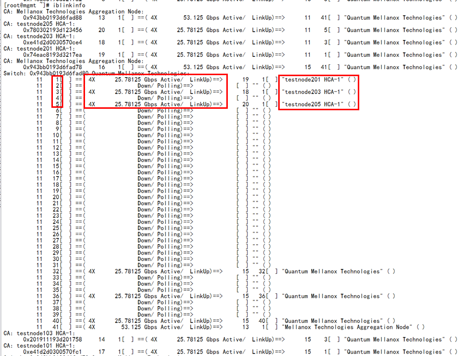
Figure 27 Verifying the network topology (2)
Verifying the physical link state
Execute the ibdiagnet command at SM nodes to check the health state of the physical fiber link. In this way, you can check whether the fiber is damaged or the connection is unstable. As shown in Figure 28, if the values of Errors and Warnings are 0, it indicates that the physical link is normal; if there is an error message, you can view the log in /var/tmp/ibdiagnet/.
Figure 28 Verifying the physical fiber link (1)
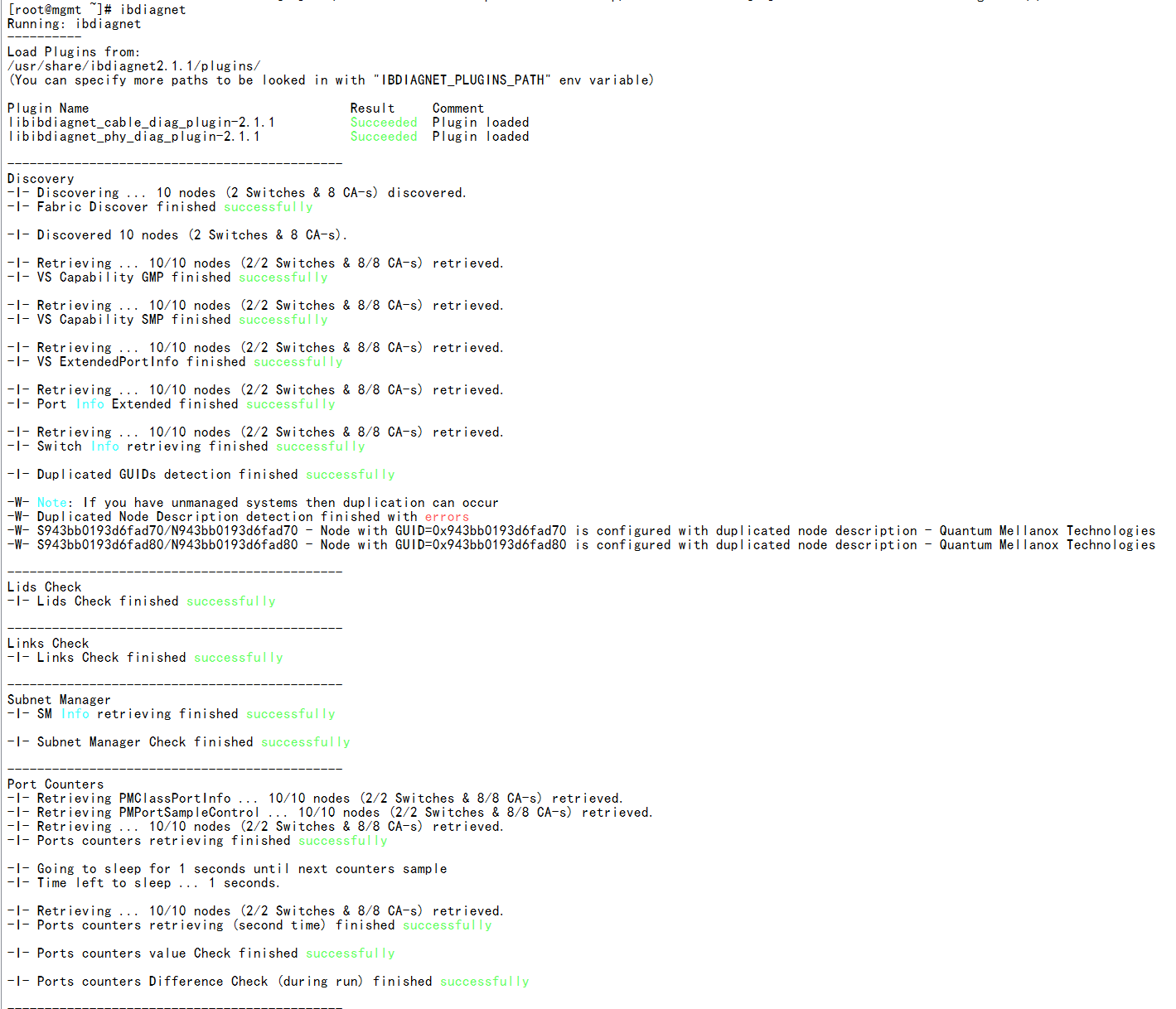
Figure 29 Verifying the physical fiber link (2)
Verifying network bandwidth
After completing the network link check, perform the following steps to check the IB network bandwidth between any two blade servers.
1. Select any two blade servers, with one serving as the server side and the other as the client side.
2. Execute the ib_write_bw -d mlx5_0 -F -R --report_gbits --run_infinitely command at the server side.
3. Execute the ib_write_bw -d mlx5_0 ip_address -F -R --report_gbits --run_infinitely command at the client side. ip_ address represents the system IP address at the server side.
4. As shown in Figure 30, you can see that the measured bandwidth rate reaches more than 96% of the maximum bandwidth, which indicates that the performance is normal.
Figure 30 Verifying network bandwidth

Common operations
Install IB network adapter driver
Install the IB network adapter driver as follows:
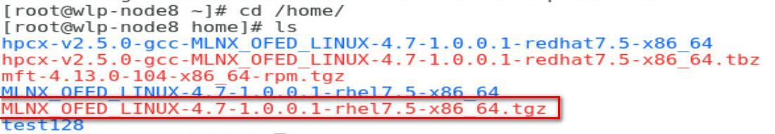
1. Copy the IB network adapter driver file to the operating system of the blade server. In this example, the /home directory is used as an example.
Figure 31 Uploading the driver
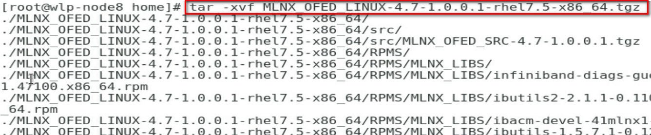
2. Decompress the IB network adapter driver file in the /home directory.
Refer to the tar –xvf MLNX_OFED_LINUX-4.7-1.0.0.1-rhel7.5-x86_64.tgz command.
Figure 32 Decompressing the driver file
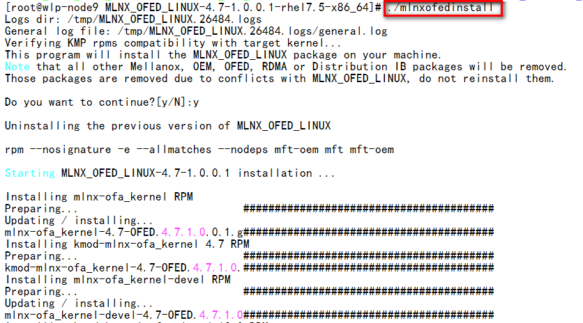
3. Go to the MLNX_OFED_LINUX-4.7-1.0.0.1-rhel7.5-x86_64/ directory, and execute the ./mlnxofedinstall command for installing the IB network adapter driver.
Figure 33 Installing the IB network adapter driver
4. After installing the driver successfully, restart the server.
Figure 34 Restarting the server

Install the MFT tool
MFT is a set of firmware management tools for producing the standardized or customized Mellanox firmware images, querying firmware information, and downloading firmware images.
Install the MFT tool as follows:
1. Copy the MFT tool file to the operating system of the blade server. In this example, the /home/uis directory is used as an example.
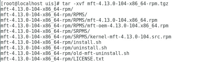
2. As shown in Figure 35, go to the /home/uis directory and execute the tar -xvf mft-4.13.0-104-x86_64-rpm.tgz command to decompress the general MFT toolkit for IB.
Figure 35 Decompressing the MFT toolkit
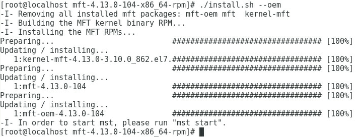
3. As shown in Figure 36, go to the /home/ mft-4.13.0-104-x86_64-rpm directory, and execute the ./install.sh --oem command for installing the MFT tool.
Figure 36 Installing the MFT tool
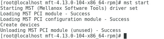
4. As shown in Figure 37, execute the mst start command to run the MFT tool.
Figure 37 Running the MFT tool