- Table of Contents
-
- H3C CR16000-F Router Series Installation Guide-5W107
- 00-Preface
- 01-Chapter 1 Preparing for Installation
- 02-Chapter 2 Installing the Router
- 03-Chapter 3 Installing FRUs
- 04-Chapter 4 Connecting Your Router to the Network
- 05-Chapter 5 Troubleshooting
- 06-Chapter 6 Replacement Procedures
- 07-Appendix A Engineering Labels for Cables and Devices
- 08-Appendix B Cabling Recommendations
- 09-Appendix C Repackaging the Router
- Related Documents
-
| Title | Size | Download |
|---|---|---|
| 06-Chapter 6 Replacement Procedures | 4.82 MB |
Contents
Replacing a transceiver module
Replacing an XFP/QSFP+/QSFP28/SFP28/SFP+/SFP transceiver module
Replacing a CFP transceiver module
Replacing a CFP2 transceiver module
Replacing an SMB coaxial clock cable
Replacement procedures
|
WARNING! To avoid device damage and bodily injury, strictly follow the replacement procedures to replace the removable components on the router. · Do not hot swap hard disks. · Be aware of electrical safety hazards when hot swapping a component on the router. The following components are hot swappable: ¡ Power supplies ¡ Cards ¡ Subcards ¡ Fan trays ¡ Air filters ¡ Transceiver modules |
|
|
CAUTION: As a best practice to avoid data theft, remove all data from an FRU that has a storage medium, for example, a CF card, hard disk, or flash before disposal of that FRU. To remove data, format or destroy the storage medium on the FRU. |
The router uses a modular architecture. You can replace the removable components on the router.
Replacing a power supply
This section describes the precautions and procedures for replacing a power supply.
Replacement precautions
Before you replace a power supply, read the following precautions carefully:
· Strictly follow the procedures shown in Figure 1 and Figure 2 to replace a power supply to avoid device damage or bodily injury.
· Power supplies on a router must be the same model. The model of the replacement power supply must be the same as the model of the power supplies that are operating correctly. If not, disconnect the power supply and remove all power supplies before replacement.
· Add a circuit breaker to the power line for each power supply. Before replacing a power supply, turn off its circuit breaker.
· The power supply might be of high temperature. Remove it with caution.
· To install the removed power supply to the chassis again, install it after the status LED on the power supply is off.
· After removing the power supply, if you do not install a new power supply, install a filler panel.
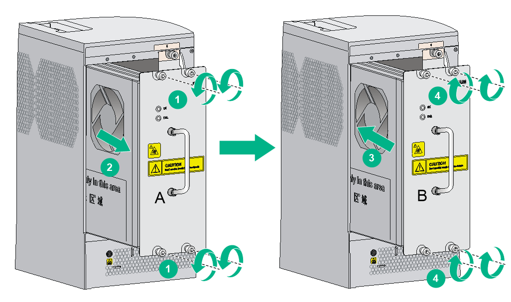
Figure 1 Power supply removal flow
![]()
Figure 2 Power supply installation flow
![]()
Replacement procedures
To replace a power supply with a captive screw:
1. Prepare an antistatic mat to place the removed power supply.
2. Turn off the circuit breaker.
3. Wear an ESD wrist strap and make sure it makes good skin contact and is correctly grounded. For more information, see "Attaching an ESD wrist strap."
4. Remove the power cord from the power supply:
¡ AC power cord—Remove the cable tie from the power cord, and remove the power cord plug from the power supply.
¡ DC power cord from an LSUM1DC2400 or PSR2400-12D power supply—Remove the cable tie from the power cord, loosen the fastening screw on the power cord, and remove the power cord plug from the power supply.
¡ DC power cord from a PSR2400-D power supply—Remove the cable tie from the power cord, remove the protection cover over the wiring terminals, remove the screws on the wiring terminals, and then remove the power cord lugs.
5. Use a Phillips screwdriver to loosen the captive screw on the power supply, and then grasp the captive screw between your thumb and index finger to carefully pull out the handle on the power supply.
6. Holding the power supply handle with one hand and supporting the bottom of the power supply with the other, gently pull the power supply out.
7. Put the removed power supply on the antistatic mat.
8. Install a new power supply. For the installation procedures, see "Installing a power supply."
Figure 3 Removing a power supply with a captive screw (AC)
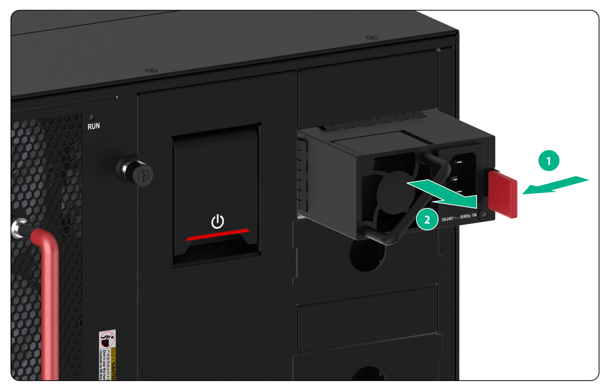
To replace a power supply with a latch:
1. Prepare an antistatic mat to place the removed power supply.
2. Turn off the circuit breaker.
3. Wear an ESD wrist strap and make sure it makes good skin contact and is correctly grounded. For more information, see "Attaching an ESD wrist strap."
4. Remove the power cord from the power supply:
¡ AC power cord—Remove the cable tie from the power cord, and remove the power cord plug from the power supply.
¡ DC power cord from a PSR2400-D power supply—Remove the cable tie from the power cord, remove the protection cover over the wiring terminals, remove the screws on the wiring terminals, and then remove the power cord lugs.
5. Holding the power supply handle with one hand and pinching the latch of the power supply, gently pull the power supply partly out of the slot.
6. Supporting the bottom of the power supply with the other hand, gently pull the power supply totally out of the slot.
7. Put the removed power supply on the antistatic mat.
8. Install a new power supply. For the installation procedures, see "Installing a power supply."
Figure 4 Removing a power supply with a latch (AC)
Replacing a card
|
|
CAUTION: · The cards on the routers are hot swappable. However, to remove the only MPU on the router, you must first power off the router. · To replace an MPU or service module, first remove all its cables. · Replace all Type-A switching fabric modules if one of them needs to be replaced. For more information, see H3C CR16000-F Router Series Hardware Information and Specifications. |
The replacement procedure is the same for the cards installed in horizontal or vertical slots. The following procedure replaces a card in a horizontal slot.
To replace a card:
1. Prepare an antistatic mat to place the removed card.
2. Wear an ESD wrist strap and make sure it makes good skin contact and is correctly grounded. For more information, see "Attaching an ESD wrist strap."
3. Use a Phillips screwdriver to loosen the captive screws on the card.
4. Press the ejector buttons on the ejector levers to release the ejector levers. (This step is applicable only to a switching fabric module with ejector buttons on the ejector levers.)
5. Press the ejector levers down so that they are vertical to the front panel. (This step applies only to ejector levers similar to those on a CSPEX-1504X card.)
6. Open the locking clip or micro switch, if any, on the module.
7. Move the ejector levers outwards to separate the card from the backplane.
8. Use one hand to slowly move the card outwards. Supporting the bottom of the card with the other hand, pull the card out of the slot along slide rails.
9. Put the removed card on the antistatic mat.
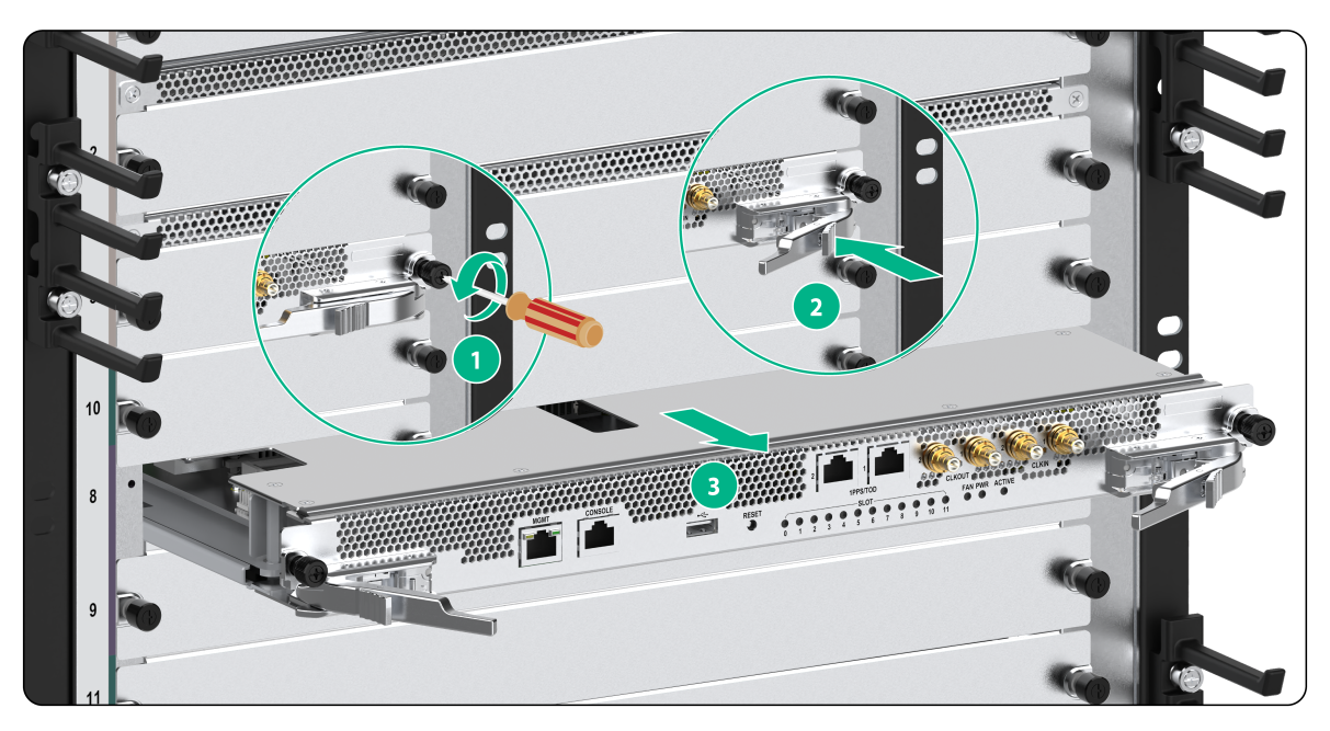
Figure 5 Removing a common card
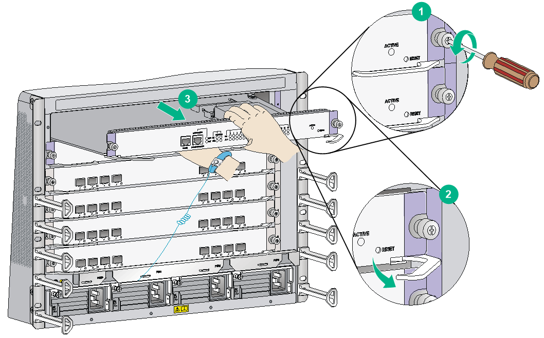
Figure 6 Removing a card with a locking clip
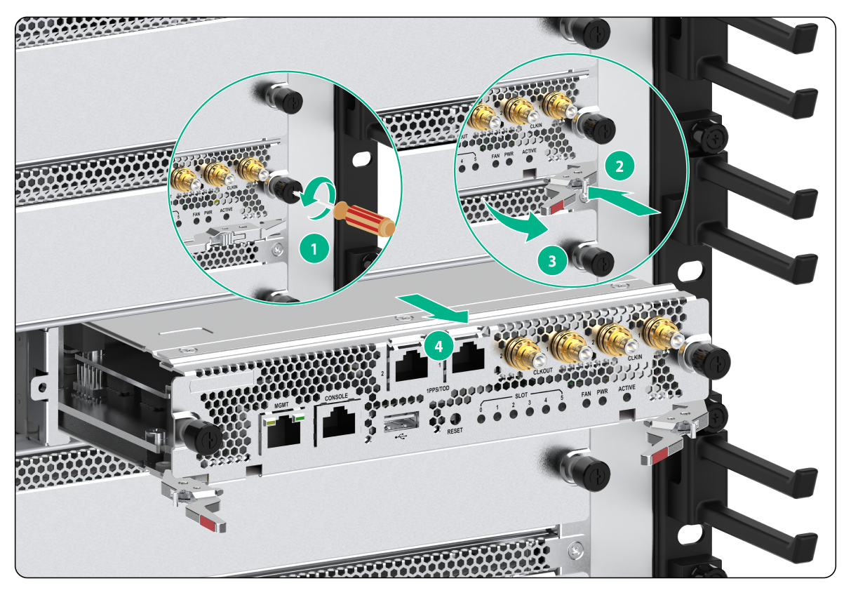
Figure 7 Removing a card with a micro switch
10. Install a new card. For the installation procedure, see "Installing MPUs/service modules/switching fabric modules."
If you are not to install a new card, perform the following tasks to ensure adequate ventilation and dust prevention:
¡ If a service module with a height of 1.2U is removed from a CR16010H-F or CR16010H-FA, a CR16018-F or CR16018-FAa CR16005E-F or CR16010E-F router, install a filler panel in the slot and an air duct above the slot immediately.
¡ If another type of card is removed from the card, install a filler panel in the slot immediately.
Replacing a subcard
|
|
CAUTION: All subcards except for the MIC-SM are hot swappable. |
This section describes the procedure for replacing a subcard on a base card.
To replace a subcard:
1. Prepare an antistatic mat to place the removed subcard.
2. Put on an ESD wrist strap, and make sure the wrist strap makes good skin contact and is correctly grounded. For more information, see "Attaching an ESD wrist strap."
3. Identify whether the subcard is hot swappable.
¡ If the subcard is hot swappable, go to the next step.
¡ If the subcard is not hot swappable, make sure the base card is powered off.
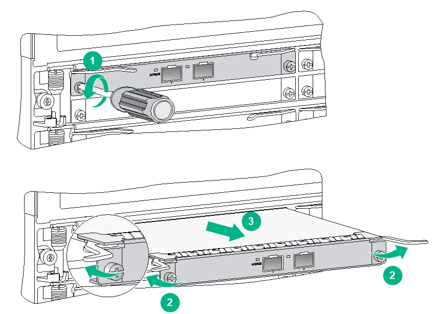
4. Use a Phillips screwdriver to loosen the captive screws on the subcard.
5. Rotate out the ejector levers to unseat the subcard from the base card.
6. Slowly pull out the subcard along the guide rails.
7. Put the removed subcard on an antistatic mat or in the original package.
8. Install the new subcard. For more information about how to install a subcard, see "Installing a subcard."
Replacing a hard disk
|
|
CAUTION: Do not hot swap a hard disk when the operating system on the hard disk is running. |
To replace a hard disk:
1. Prepare an antistatic mat to place the removed hard disk.
2. Put on an ESD wrist strap, and make sure the wrist strap makes good skin contact and is reliably grounded. For more information, see "Attaching an ESD wrist strap."
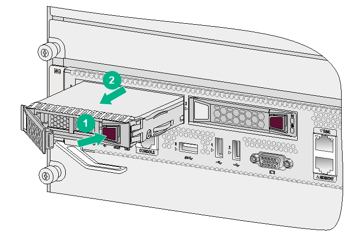
3. Press the button on the hard disk panel. The hard disk panel will open automatically.
4. Gently pull out the hard disk along the guide rails.
5. Install the new hard disk. For more information about how to install a hard disk, see "Installing a hard disk."
Figure 9 Removing a hard disk
Replacing a fan tray
|
|
WARNING! To avoid bodily injury, do not touch the rotating fans when replacing a fan tray. |
|
|
CAUTION: To install fan trays in FAN 10 to FAN 14 slots on a CR16018-F or CR16018-FA router, orient the fan tray with the yellow warning sign in the upper half. To install fan trays in the other fan tray slots, orient the fan tray with the yellow warning sign in the lower half. |
The fan tray slot is vertically oriented on CR16006-F, CR16014-F, CR16010H-F, CR16010H-FA, CR16018-F, CR16018-FA, CR16005E-F, and CR16010E-F routers and horizontally oriented on a CR16010-F router.
The fan tray replacement procedure is similar for all CR16000-F routers except CR16010E-F, The following procedure uses the CR16010E-F router and other routers as examples.
To replace a fan tray on a CR16000-F router except CR16010E-F:
1. Prepare an antistatic mat to place the fan tray to be removed.
2. Put on an ESD wrist strap and make sure the wrist strap makes good skin contact and is correctly grounded. For more information, see "Attaching an ESD wrist strap."
3. Remove the captive screws on the fan tray.
4. Hold the handle of the fan tray with one hand to gently pull the fan tray part way out of the chassis. After the fans stop rotating, support the bottom of the fan tray with the other hand, and take out the fan tray from the chassis.
5. Put the removed fan tray on the antistatic mat.
6. Unpack the fan tray to be installed.
7. Holding the handle of the fan tray with one hand and supporting bottom with the other, gently slide the fan tray along the guide rails into the slot until it is firmly secured in the slot.
8. Fasten the captive screws on the fan tray.
Figure 10 Replacing a fan tray (CR16006-F)
|
(A) Fan tray to be replaced |
(B) Fan tray to be installed |
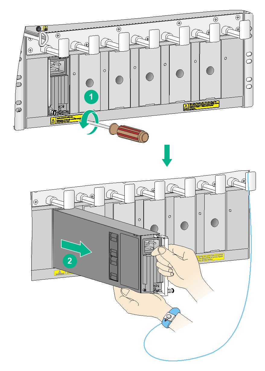
To replace a fan tray on a CR16010E-F router:
1. Prepare an antistatic mat to place the fan tray to be removed.
2. Put on an ESD wrist strap and make sure the wrist strap makes good skin contact and is correctly grounded. For more information, see "Attaching an ESD wrist strap."
3. Remove the captive screws on the fan tray.
4. Hold the handle of the fan tray to gently pull the fan tray part way out of the chassis to disconnect the fan tray from the device. After the fans stop rotating, supporting the bottom of the fan tray, take out the fan tray from the chassis.
5. Put the removed fan tray on the antistatic mat.
6. Unpack the fan tray to be installed.
7. Holding the handle of the fan tray with one hand and supporting bottom with the other, gently slide the fan tray along the guide rails into the slot until it is firmly secured in the slot.
8. Release the handle of the fan tray and fasten the captive screws on the fan tray.
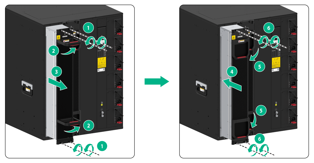
Figure 11 Replacing a fan tray (CR16010E-F)
Replacing an air filter
|
|
CAUTION: Clean air filters every month to guarantee adequate ventilation and avoid over-temperature. |
Keep the removed screws secure from loss when replacing an air filter on a CR16006-F or a CR16014-F router.
1. Loosen the screws on the air filter.
2. Remove the air filter from the chassis.
Figure 12 Removing the air filter from the CR16010-F chassis
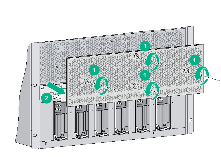
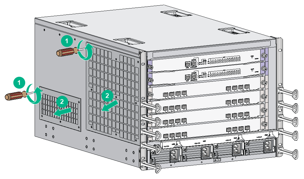
Figure 13 Removing the air filter from the other models
3. Attach the cleaned air filter to the router.
For the installation procedures, see "(Optional) Installing an air filter on the chassis."
Replacing a CF card
|
|
CAUTION: To avoid hardware or file system damage, do not remove a CF card when the router is booting or the CF card LED is flashing. |
The CF card is installed on the MPU of the router.
To replace a CF card:
1. Observe the CF card LED status.
¡ If the LED is on, you cannot remove the CF card. You must use the umount command in user view to unmount the CF card and wait until the CF card LED is off. If you want to continue to use the CF card, execute the mount command in user view to mount the CF card again.
For more information about the umount and mount commands, see file system management in H3C CR16000-F Routers Fundamentals Command Reference.
¡ If the LED is flashing, data is being read from or written to the CF card. Only after the LED stops flashing, you can remove the CF card.
¡ If the LED is off, the CF card is unmounted. You can remove the CF card.
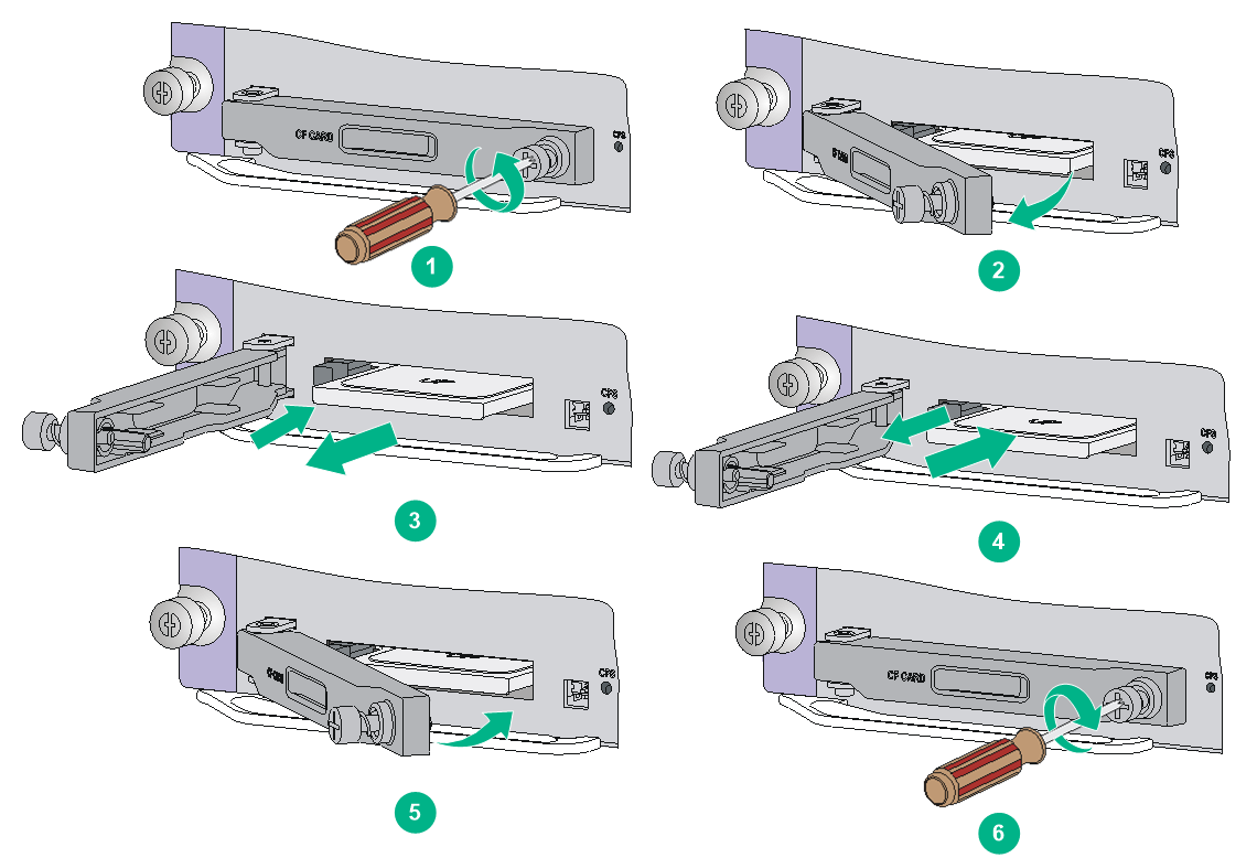
2. Use a Phillips screwdriver to loosen the screw at the right side of the CF card protection cover, and open the CF card protection cover.
Skip this step if the MPU does not have a CF card protection cover.
3. Push the eject button on the CF card slot all the way until the CF card in the slot ejects. Remove the CF card from the slot, and put the removed CF card on an antistatic bag or into its original package.
4. Before inserting the CF card, make sure the CF card eject button is pushed to the end and does not reset automatically. Push the new CF card all the way into the CF card slot until the eject button resets.
5. Close the CF card cover and use a Phillips screwdriver to fasten the screw on the CF card protection cover.
Skip this step if the MPU does not have a CF card protection cover.
Figure 14 Replacing a CF card
Replacing a transceiver module
|
|
WARNING! Disconnected optical fibers or transceiver modules might emit invisible laser light. Do not stare into beams or view directly with optical instruments when the switch is operating. |
|
|
CAUTION: · Do not touch the golden plating on a transceiver module during the replacement process. · Make sure the new transceiver module is the same model as the peer transceiver module at the other end of the optical fiber. · In case of limited space, you can use the provided tweezers and other tools to remove a transceiver module or optical fiber. |
Replacing an XFP/QSFP+/QSFP28/SFP28/SFP+/SFP transceiver module
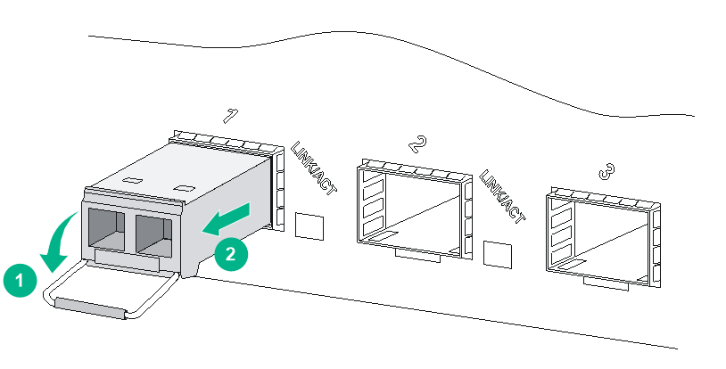
The replacement procedure is similar for XFP, QSFP+, QSFP28, SFP28, SFP+, and SFP transceiver modules. The following uses an SFP+ transceiver module for illustration.
To replace an SFP+ transceiver module:
1. Wear an ESD wrist strap and make sure it makes good skin contact and is correctly grounded.
For more information, see "Attaching an ESD wrist strap."
2. Remove the optical fibers from the module.
There is a latching mechanism between a fiber connector and transceiver module bore to prevent connector disengagement. Release the latching mechanism before removing the optical fiber. To avoid damages, do not use excessive force.
3. Pivot the bail latch down to the horizontal position.
4. Hold the bail latch to pull the module out of the slot. Make sure you apply force in the direction parallel to the ground. To avoid damaging the bail latch, do not use excessive force.
If you apply force at an angle when pulling the module out, you can hardly pull the module out and the module or fiber port might be damaged.
5. Insert dust plugs into the removed module, and put the module into its packaging bag.
6. Install a new module. For the installation procedure, see "Installing an XFP/QSFP+/QSFP28/SFP28/SFP+/SFP module."
Figure 15 Removing an SFP+ transceiver module
Replacing a CFP transceiver module
1. Wear an ESD wrist strap and make sure it makes good skin contact and is reliably grounded.
For more information, see "Attaching an ESD wrist strap."
2. Remove the optical fibers from the module.
There is a latching mechanism between a fiber connector and transceiver module bore to prevent connector disengagement. Release the latching mechanism before removing the optical fiber. To avoid damages, do not use excessive force.
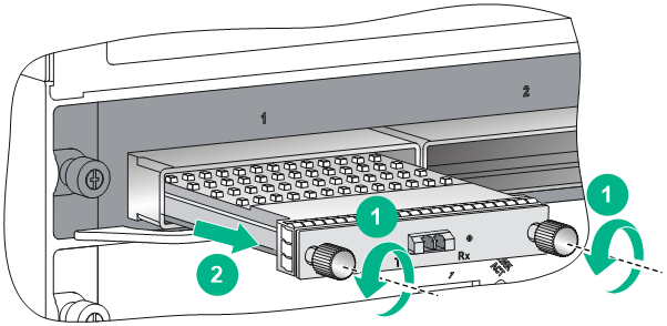
3. Loosen the captive screws on the module.
4. Carefully pull the module out of the slot. Make sure you apply force in the direction parallel to the ground.
If you apply force at an angle, you can hardly pull the module out and the module or fiber port might be damaged.
5. Insert the plugs into the removed module, and put the module into its packaging bag.
6. Install a new module. For the installation procedure, see "Installing a CFP module."
Figure 16 Removing a CFP transceiver module
Replacing a CFP2 transceiver module
1. Wear an ESD wrist strap and make sure it makes good skin contact and is reliably grounded.
For more information, see "Attaching an ESD wrist strap."
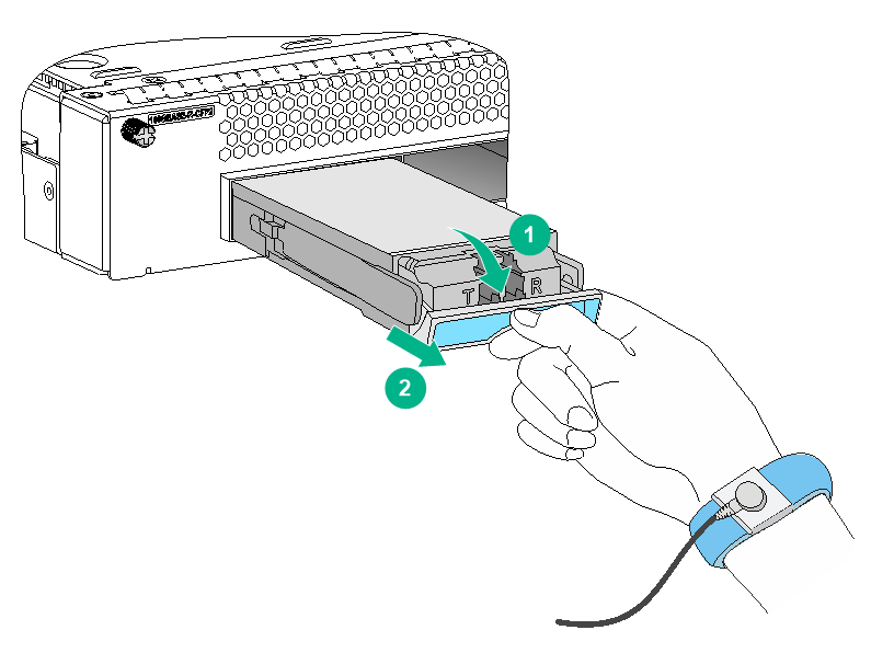
2. Remove the optical fibers from the module and pivot down the handle so that the handle is parallel with the module body.
3. Hold the handle to pull the module out.
To avoid damaging the handle, do not use excessive force.
4. Insert dust plugs into the transceiver module ports and put the transceiver module in its package.
5. Install a new CFP2 transceiver module. For the installation procedure, see "Installing a CFP2 transceiver module."
Figure 17 Removing a CFP2 transceiver module
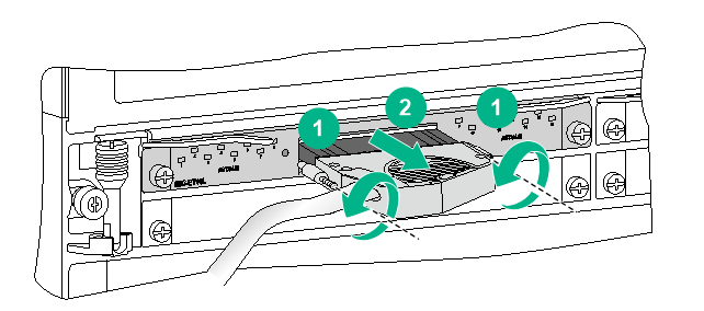
Replacing an E1 cable
1. Wear an ESD wrist strap and make sure it makes good skin contact and is reliably grounded.
For more information, see "Attaching an ESD wrist strap."
2. Use a screwdriver to loosen the screws on the connector of the E1 cable.
3. Pull out the E1 cable slowly.
Figure 18 Removing an E1 cable
4. Install a new E1 cable.
For the installation procedure, see "Connecting an E1 cable."
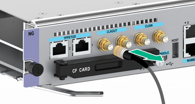
Replacing an SMB coaxial clock cable
1. Wear an ESD wrist strap and make sure it makes good skin contact and is reliably grounded. For more information, see "Attaching an ESD wrist strap."
2. Remove the SMB coaxial clock cable from the clock port.
3. Install a new SMB coaxial clock cable. For the installation procedure, see "Installing an SMB coaxial clock cable".
4. If you are no to install a new SMB coaxial clock cable after removing the old one, insert a dust plug into the clock port.
Figure 19 Replacing an SMB coaxial clock cable