- Table of Contents
-
- H3C CR16000-F Router Series Installation Guide-5W107
- 00-Preface
- 01-Chapter 1 Preparing for Installation
- 02-Chapter 2 Installing the Router
- 03-Chapter 3 Installing FRUs
- 04-Chapter 4 Connecting Your Router to the Network
- 05-Chapter 5 Troubleshooting
- 06-Chapter 6 Replacement Procedures
- 07-Appendix A Engineering Labels for Cables and Devices
- 08-Appendix B Cabling Recommendations
- 09-Appendix C Repackaging the Router
- Related Documents
-
| Title | Size | Download |
|---|---|---|
| 04-Chapter 4 Connecting Your Router to the Network | 831.21 KB |
Connecting your router to the network
Accessing the router for the first time
Setting up the configuration environment
Downloading a USB-to-serial driver
Connecting the router to the network
Connecting your router to the network through twisted pair cables
Connecting your router to the network through optical fibers
Testing the network connectivity
Connecting your router to the network
The first time you access the router, you can only log in to the CLI through the console port or USB console port. After login, you can configure other access methods. The router supports also remote access through Telnet or SSH.
The router provides the following types of user lines:
· Console user line—Manages and monitors users that logs in to the router through the console port.
· AUX user line—Manages and monitors users that logs in to the router through the USB console port.
· Virtual type terminal (VTY) line—Manages and monitors users that logs in to the router through Telnet or SSH.
For more information about login methods and user lines, see login management in H3C CR16000-F Routers Fundamentals Configuration Guide.
Accessing the router for the first time
The first time you access the router you must use a console cable to connect the console port or USB console port on the router to a configuration terminal, a PC for example.
Setting up the configuration environment
If two MPUs are installed on a router, you can use the console port or USB console port on either of the MPU for connecting to a terminal.
Console cables
· Console cable connecting the console port on a router and the serial port on a terminal
The console cable has a crimped RJ-45 connector for connecting to the console port of the router, and a DB-9 connector for connecting to the 9-core serial port of the terminal.
Figure 1 shows the console cable and Table 1 shows its pinouts.
Figure 1 Console cable connecting the serial port and the console port
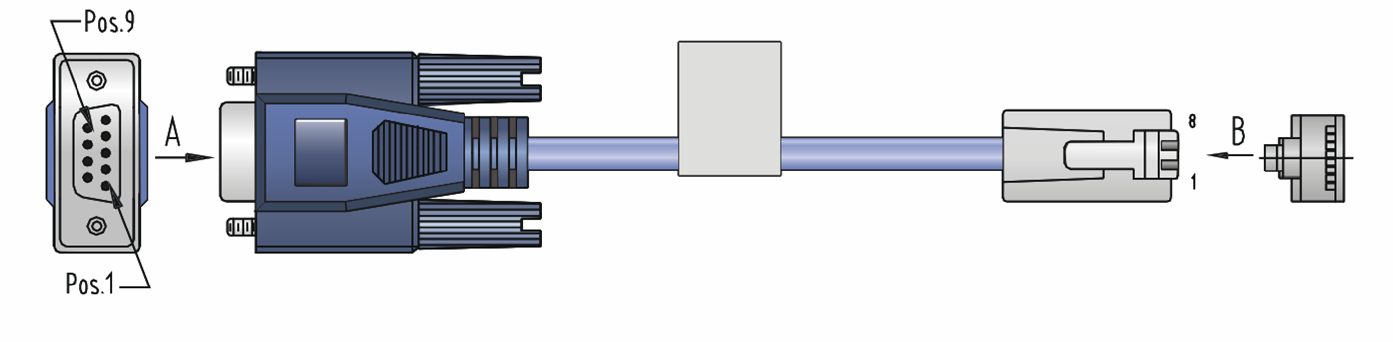
Table 1 Pinouts for the console cable connecting the serial port and the console port
|
RJ-45 pin |
Signal |
DB-9 pin |
Signal |
|
1 |
RTS |
8 |
CTS |
|
2 |
DTR |
6 |
DSR |
|
3 |
TXD |
2 |
RXD |
|
4 |
CD |
5 |
SG |
|
5 |
GND |
5 |
SG |
|
6 |
RXD |
3 |
TXD |
|
7 |
DSR |
4 |
DTR |
|
8 |
CTS |
7 |
RTS |
· Console cable connecting the USB console port on a router and the USB port on a terminal
The console cable has one USB 5-pin mini-Type B connector for connecting to the USB console port of the router and one USB Type-A connector for connecting to the USB port of the terminal.
Figure 2 shows the console cable and Table 2 shows its pinouts.
Figure 2 Console cable connecting the USB port and the USB console port
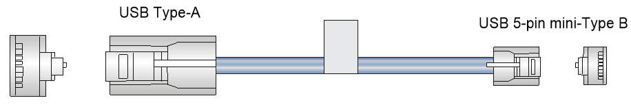
Table 2 Pinouts for the console cable connecting the USB port and the USB console port
|
USB A pin |
Signal |
mini-USB A/B pin |
Signal |
|
1 |
VBUS |
1 |
VBUS |
|
2 |
D- |
2 |
D- |
|
3 |
D+ |
3 |
D+ |
|
|
|
4 |
ID(NC) |
|
4 |
GND |
5 |
GND |
Connecting the console port to the terminal
|
|
IMPORTANT: · Identify the marks on the console port and USB console port, and make sure you are connecting to the correct port. · The serial ports on PCs do not support hot swapping. To connect a PC to an operating device, first connect the PC end. To disconnect a PC from an operating device, first disconnect the device end. |
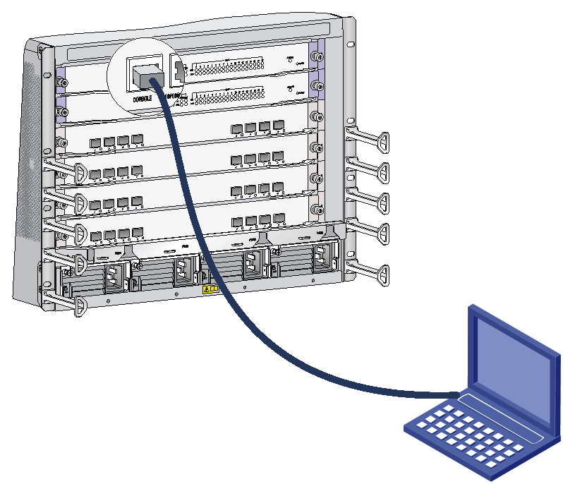
To connect the console cable to the console port:
1. Connect the DB-9 connector of the console cable to the serial port on a PC or terminal.
2. Connect the RJ-45 connector of the console cable to the console port on the MPU of the router.
To connect the console cable to the USB console port:
1. Connect the USB-A connector of the console cable to the USB port on a PC or terminal.
2. Connect the mini-USB A/B connector of the console cable to the USB console port on the MPU of the router.
Figure 3 Connecting a console port to a terminal
Downloading a USB-to-serial driver
Download and install a USB-to-serial driver that applies to your operating system. After installation, perform the following steps to verify that a USB serial port is available on your PC (Windows 7 as an example):
1. Click Start. In the Start menu, right click the My computer icon and select Manage.
2. On the Computer Management page, select Device Manager.
3. Expand Ports (COM & LPT). If XR21V1410 USB UART (COM5) is displayed, the USB-to-serial driver has been installed successfully.
Setting terminal parameters
To access the device through the console port or USB console port, you must run a terminal emulator program (TeraTermPro or PuTTY) on the configuration terminal. For information about how to use a terminal emulator program, see the program's user guide.
The following are the required terminal settings:
· Baud rate—9600.
· Data bits—8.
· Stop bits—1.
· Parity—none.
· Flow control—none.
Powering on the router
|
|
IMPORTANT: The CR16010H-F/CR16010H-FA/CR16018-F/CR16018-FA/CR16005E-F/CR16010E-F routers each have two power switches. To power on the router, turn on both power switches. |
Before powering on the router, verify the following items:
· You know where the emergency power-off router for the equipment room is located.
· The router has been securely mounted.
· All the cards have been correctly installed.
· The unused slots have been installed with filler panels.
· All the network cables, fibers, power cords, and grounding cables have been correctly connected.
· The input power voltage meets the requirement of the router.
· The console cable is correctly connected.
· The terminal or PC used for configuration has started, and the configuration parameters have been set.
To power on the router:
1. Turn on the power source of the router.
The following is a sample output you can see on the terminal (console port login):
System is starting...
Press Ctrl+D to access BASIC-BOOTWARE MENU...
Press Ctrl+T to start memory test
Booting Normal Extended BootWare
The Extended BootWare is self-decompressing.........Done.
…
BootWare Validating...
Press Ctrl+B to access EXTENDED-BOOTWARE MENU...
2. Enter 1.
The system image file is loaded.
Enter your choice(0-9): 1
Loading the main image files...
Loading file flash:/temp-system.bin...........................
............................................................................
............................................................................
.............................Done.
Loading file flash:/temp-boot.bin.............................
......Done.
Image file flash:/temp-boot.bin is self-decompressing.........
................................................................Done.
System image is starting...
Finished running batch file.
Line con0 is available.
Press ENTER to get started.
When the prompt <Sysname> appears, you can configure the router.
After powering on the router, check the following items:
· The cooling system is working, and you can hear fan rotating noise and feel air being blown out.
· The system status LEDs on the MPUs show that the system is operating normally. For more information about LED behaviors, see H3C CR16000-F Router Series Hardware Information and Specifications.
Connecting the router to the network
Before you connect the router to the network, configure basic settings for the router. For more information, see login management in H3C CR16000-F Routers Fundamentals Configuration Guide.
Connecting your router to the network through twisted pair cables
The router provides 10/100BASE-TX ports, 1000BASE-T ports, and 10GBASE-T ports. These ports use RJ-45 connectors and support auto-MDI/MDI-X. Use category-6A or category-7 twisted pair cables to connect 10GBASE-T ports and category-5 or above to connect other ports. For more information about twisted pair cables, see H3C CR16000-F Router Series Hardware Information and Specifications.
To connect a 10/100BASE-TX or 1000BASE-T port to a peer device:
1. Connect one end of a twisted pair cable to the port.
2. Connect the other end of the twisted pair cable to the RJ-45 Ethernet port of the peer device.
3. Check the port LEDs for incorrect connection.
For more information about the LED status, see H3C CR16000-F Router Series Hardware Information and Specifications.
Connecting your router to the network through optical fibers
|
|
WARNING! Disconnected optical fibers or transceiver modules might emit invisible laser light. Do not stare into beams or view directly with optical instruments when the switch is operating. |
Before connecting optical fibers to a fiber port, install a transceiver module in the port. For information about installing transceiver modules, see "(Optional) Installing transceiver modules". For more information about optical fibers, see H3C CR16000-F Router Series Hardware Information and Specifications.
To connect a fiber port to a peer device through optical fibers:
1. Install a transceiver module into the port.
2. Remove the dust cover of the optical fiber connector, and clean the end of the optical fiber.
3. Remove the dust plug of the transceiver module, connect one end of the optical fiber to the transceiver module, and connect the other end to the transceiver module in the peer device.
4. Verify that the port LED status is correct
For more information about the LED status, see H3C CR16000-F Router Series Hardware Information and Specifications.
|
|
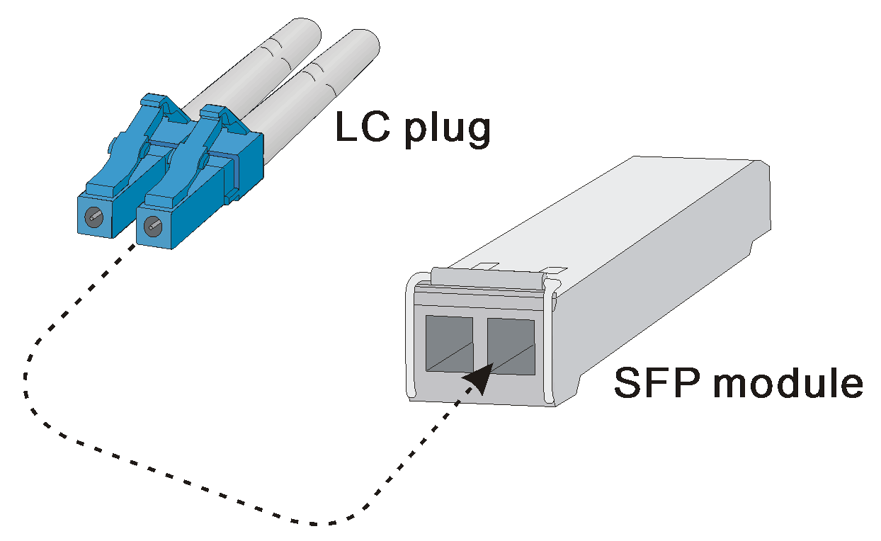
NOTE: The transceiver modules each require two optical fibers. The transmitter (TX) port on one end must connect to the receiver (RX) port on the other end. |
Figure 4 Using an LC optical fiber connector to connect an SFP module
Testing the network connectivity
After you connect the router to the network, use the ping or tracert command to test the network connectivity. For more information about these commands, see system maintenance and debugging commands in H3C CR16000-F Routers Network Management and Monitoring Command Reference.
