- Table of Contents
-
- H3C CR16000-F Router Series Installation Guide-5W107
- 00-Preface
- 01-Chapter 1 Preparing for Installation
- 02-Chapter 2 Installing the Router
- 03-Chapter 3 Installing FRUs
- 04-Chapter 4 Connecting Your Router to the Network
- 05-Chapter 5 Troubleshooting
- 06-Chapter 6 Replacement Procedures
- 07-Appendix A Engineering Labels for Cables and Devices
- 08-Appendix B Cabling Recommendations
- 09-Appendix C Repackaging the Router
- Related Documents
-
| Title | Size | Download |
|---|---|---|
| 03-Chapter 3 Installing FRUs | 4.32 MB |
Installing MPUs/service modules/switching fabric modules
(Optional) Installing transceiver modules
Installing an XFP/QSFP+/QSFP28/SFP28/SFP+/SFP transceiver module
Installing a CFP transceiver module
Installing a CFP2 transceiver module
Installing an SMB coaxial clock cable
Installing FRUs
There is no required order for installing FRUs. As a best practice, connect power cords after FRUs installation are complete.
|
|
NOTE: Keep the packages of the chassis and components for future use. |
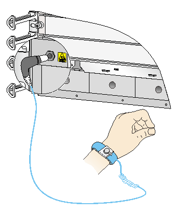
Attaching an ESD wrist strap
The CR16000-F router is shipped with an ESD wrist strap. To minimize ESD damage to electronic components, wear the ESD wrist strap and make sure it is reliably grounded when installing modules.
To use an ESD wrist strap:
1. Make sure the router is reliably grounded. For how to ground your router, see "Grounding the router."
2. Put on the wrist strap.
3. Tighten the wrist strap to keep good skin contact. Make sure the resistance reading between your body and the ground is between 1 and 10 megohms.
4. As shown in Figure 1, insert the ESD wrist strap into the ESD port on the router chassis, or attach it to the grounding post of the chassis with an alligator clip.
Figure 1 Attaching an ESD wrist strap
Installing MPUs/service modules/switching fabric modules
|
|
CAUTION: · Before installing a card, make sure the connectors on the card are not broken or blocked to avoid damaging the backplane. · To ensure good ventilation, install a filler panel over an empty MPU, service module, or switching fabric module slot. MPU slots and service module slots use the same type of filler panels. · The switching fabric modules for the CR16010-F, CR16014-F, CR16010H-F, CR16010H-FA,CR16018-FA, and CR16018-F routers each are shipped with a protection box. Before you install these switching fabric modules, pull the ejector levers on the module outwards, and then pull the module out of the protection box. · When installing a universal open application platform on a CR16006-F, a CR16010-F, or a CR16014-F router, install the provided slot adapter above the platform. The slot adapter occupies two slots. The installation method for a slot adapter is the same as a filler panel. |
The installation procedures for MPUs, service modules, and switching fabric modules are the same. Unless otherwise stated, MPUs, service modules, and switching fabric modules are collectively referred to as "cards" in this document. These cards are hot swappable.
The card slots on the router are either horizontally oriented or vertically oriented. When installing a card in a horizontal slot, make sure its PCB faces up. When installing a card in a vertical slot, make sure its PCB faces left. The following procedure installs a card in a horizontal slot.
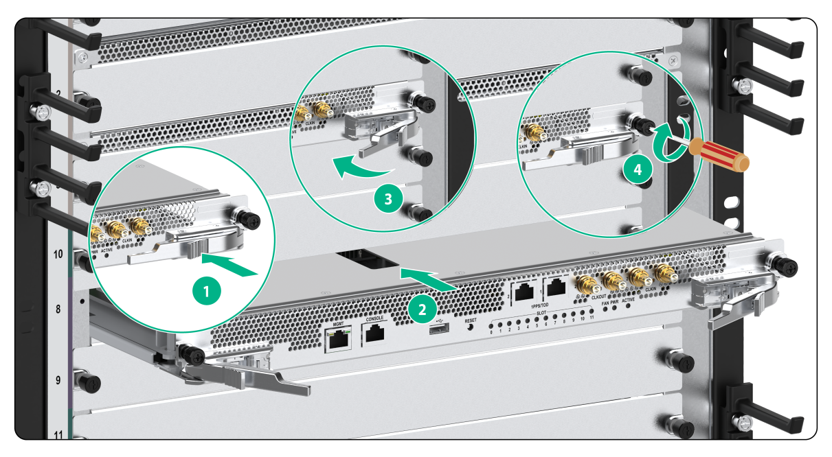
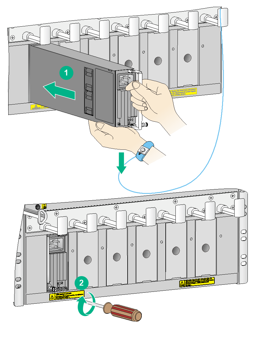
To install a card in a horizontal slot:
1. Wear an ESD wrist strap, and make sure it makes good skin contact and is reliably grounded. For more information, see "Attaching an ESD wrist strap."
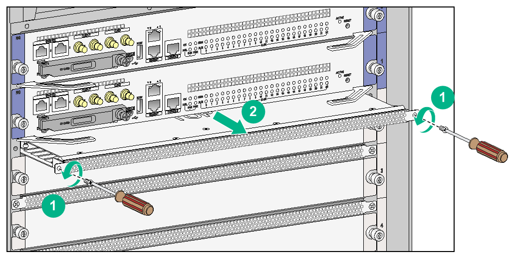
2. Remove the filler panel (if any) from the target slot.
Keep the filler panel secure for future use.
Some card slots do not have a filler panel. The figures in this section are for illustration only.
3. Remove the air duct above the module slot. (This step is required only when you install a service module with a height of 1.2U on the router that has air ducts.)
Figure 2 Removing an air duct
4. Press the ejector levers down so that they are vertical to the front panel. (This step applies only to ejector levers similar to those on a CSPEX-1504X card.)
5. Open the locking clip or micro switch, if any, on the module.
6. Hold the card by the front panel with one hand and support the card bottom with the other. Slide the card steadily into the slot along the guide rails.
7. When most part of the card is inserted in the slot, pull the ejector levers on the card outward.
8. Push the card until the positioning pin on card touches the hole on the chassis.
9. Press the ejector levers inward until the ejector levers touch the panel tightly and the card seats into the backplane
10. Push the ejector levers up to its original position. (This step applies only to ejector levers similar to those on a CSPEX-1504X card.)
11. Close the locking clip or micro switch, if any, on the module.
12. Fasten the captive screws on the card.
13. When the router is powered on, check the running status of the card.
You can determine the running status of a card by observing the card status LED (SLOT) on the MPU of the router. If the RUN LED blinks, the card in the slot operates correctly. For more information about card status LED (SLOT), see H3C CR16000-F Router Series Hardware Information and Specifications.
Figure 3 Installing a universal card
Figure 4 Install a card with a locking clip
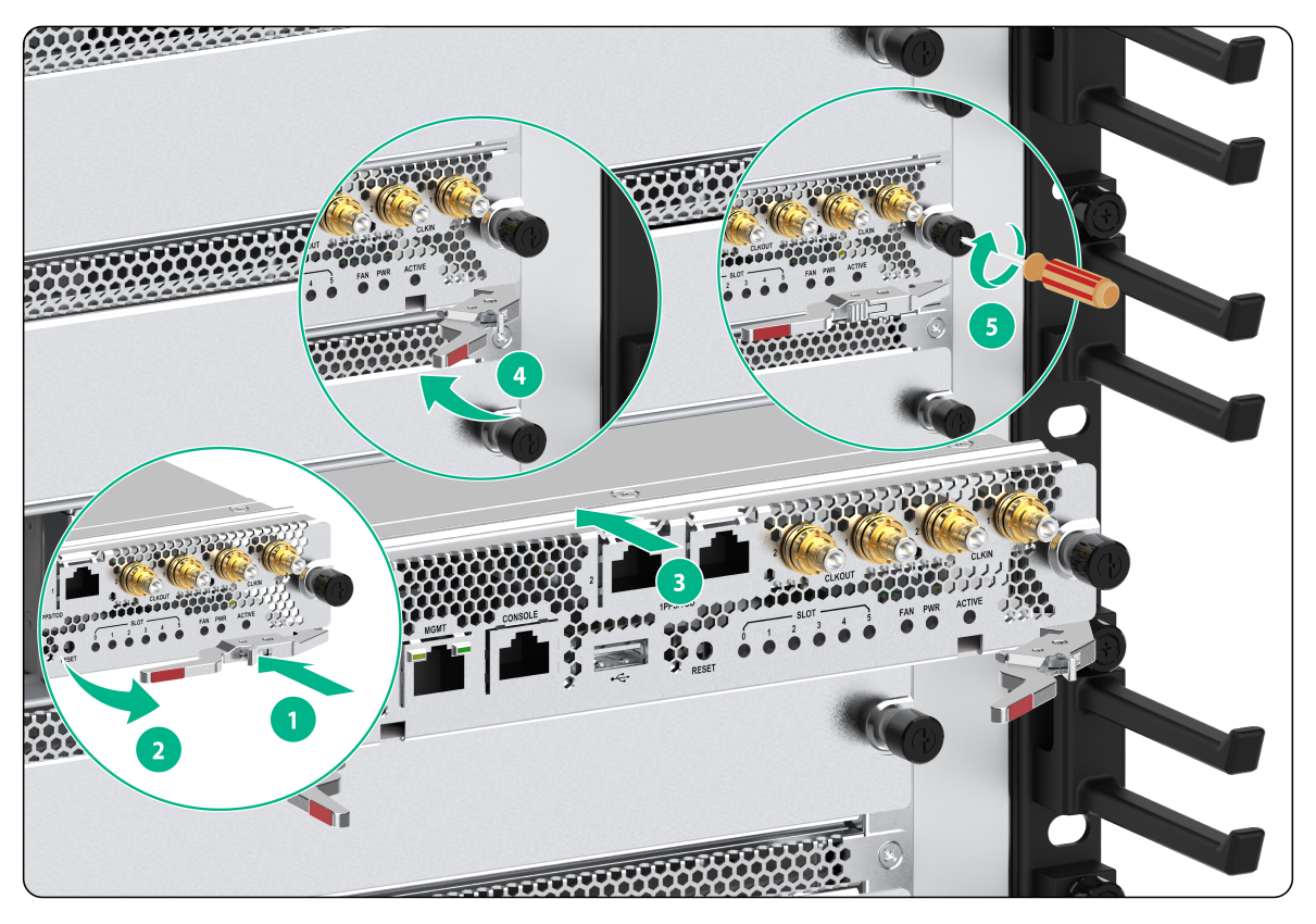
Figure 5 Install a card with a micro swtich
Installing a subcard
|
|
CAUTION: · To ensure good ventilation, install filler panels in unused slots. · All subcards except for the MIC-SM are hot swappable. |
This section describes how to install a subcard on an SPEX or MPE base card. A base card and a card use the same installation procedure. For the card installation procedure, see "Installing MPUs/service modules/switching fabric modules".
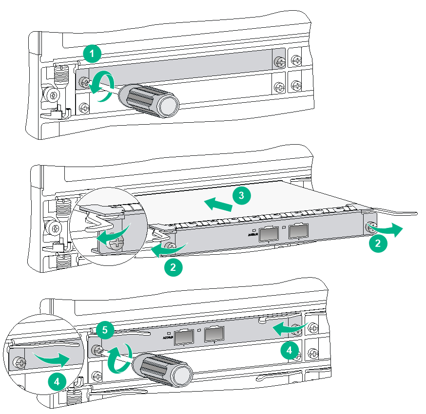
To install a subcard:
1. Wear an ESD wrist strap and make sure it makes good skin contact and is reliably grounded. For more information, see "Attaching an ESD wrist strap."
2. Identify whether the subcard is hot swappable.
¡ If the subcard is not hot swappable, make sure the base card is powered off.
¡ If the subcard is hot swappable, make sure the base card is installed on the router.
3. Unpack the subcard.
4. Remove the filler panel (if any) from the target slot on the base card.
Keep the removed filler panel secure for future use.
5. Open the ejector levers of the subcard, and gently push the subcard (with bottom up) into the slot along the guide rails until the ejector levers of the subcard touch the base card panel.
6. Push the front panel of the subcard forward. Then close the ejector levers so that the subcard is flush with the base card.
7. Use a Phillips screwdriver to fasten the screws on the subcard.
Figure 6 Installing a subcard
Installing a hard disk
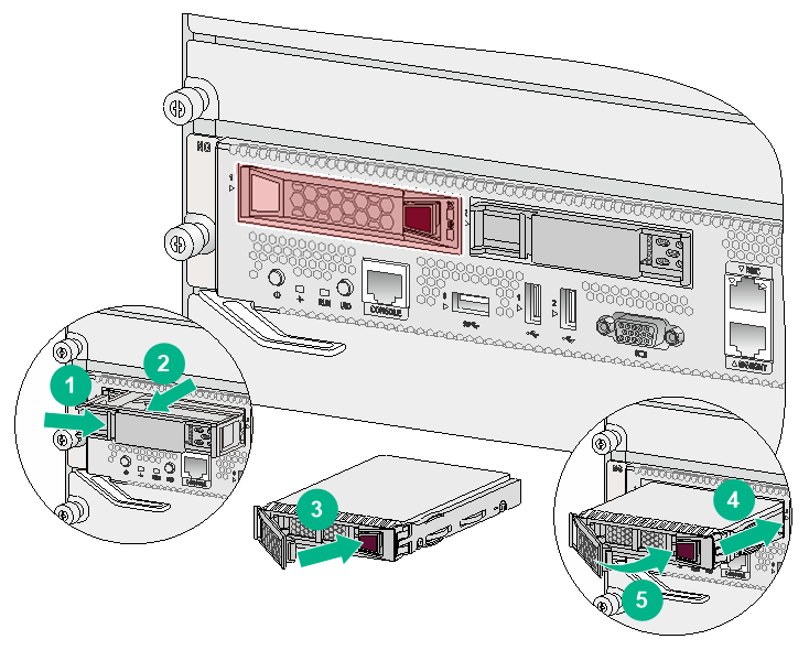
1. Wear an ESD wrist strap and make sure it makes good skin contact and is reliably grounded. For more information, see "Attaching an ESD wrist strap."
2. Make sure a universal open application platform is installed in the router.
3. Unpack the hard disk.
4. Remove the filler panel from the slot to be used.
5. Press the button on the filler panel to the right and pull the filler panel outward.
Keep the removed filler panels for future use.
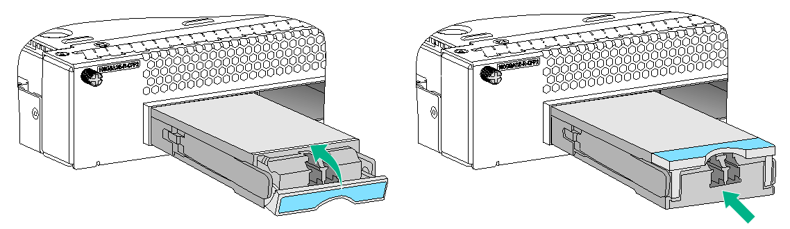
6. Press the button on the hard disk panel. The hard disk panel will open automatically.
7. Gently push the hard disk in along the guide rails.
8. Close the hard disk panel after the hard disk clicks into place.
Figure 7 Installing the hard disk
Installing a power supply
|
|
CAUTION: · Provide a circuit breaker for each power supply and make sure the circuit breaker is off before installation. · Do not install power supplies of different models on the same router. · When moving the power supply, support the bottom of the power supply, instead of holding its handle to avoid damaging the power supply. · To avoid bodily injury, strictly follow the procedure in Figure 8 to install a power supply. |
The CR16000-F router uses N + 1 or N + N power redundancy and supports AC or DC power input.
CR16000-F routers provide the following types of power supply slots:
· Horizontal slots: CR16006-F and CR16005E-F.
· Vertical slots: CR16010-F, CR16014-F, CR16010H-F, CR16010H-FA, CR16018-F, CR16018-FA, and CR16010E-F.
Figure 8 Power supply installation flow
![]()
Installing a power supply
The installation procedure is the same for AC and DC power supplies. The following procedure installs an AC power supply.
Some power supply slots do not have a filler panel. The figures in this section are for illustration only.
The CR16000-F router supports the following types of power supplies: power supplies with a captive screw and power supplies with a power latch.
To install a power supply with a captive screw:
1. Wear an ESD wrist strap and make sure it makes good skin contact and is reliably grounded. For more information, see "Attaching an ESD wrist strap."
2. Remove the filler panel, if any, from the power supply slot.
¡ If the filler panel has captive screws, use a Phillips screwdriver to loosen the captive screws on the filler panel first and then remove the filler panel.
¡ If the filler panel does not have captive screws, pull out the fill panel directly.
3. Unpack the power supply.
4. Grasping the power supply handle with one hand and supporting the power supply bottom with the other, push the power supply along the guide rails into the slot.
5. Press the handle inward until the handle seats into the slot.
6. Use a Phillips screwdriver to fasten the captive screw on the handle to attach the power supply.
Figure 9 Installing a power supply with a captive screw (CR16010-F)
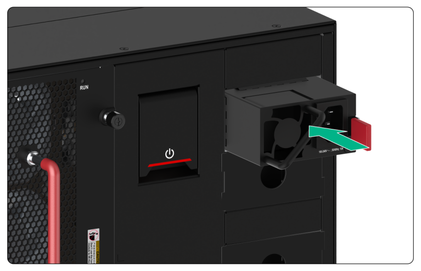
To install a power supply with a power latch:
1. Wear an ESD wrist strap and make sure it makes good skin contact and is reliably grounded. For more information, see "Attaching an ESD wrist strap."
2. Remove the filler panel, if any, from the power supply slot. Pull out the fill panel directly.
3. Unpack the power supply.
4. Grasping the power supply handle with one hand and supporting the power supply bottom with the other, push the power supply along the guide rails into the slot.
5. Press the handle inward until the power supply clicks into place.
Figure 10 Installing a power supply with a power latch (CR16005E-F)
Connecting an AC power cord
|
|
WARNING! Before you connect an AC power cord, make sure the circuit breaker for the power cord is turned off. |
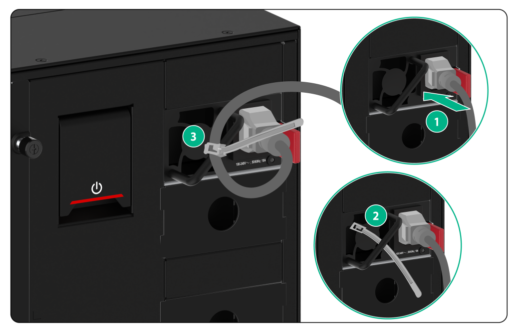
To connect an AC power cord:
1. Connect the power cord to the power receptacle on the power supply.
2. Use a releasable cable tie to secure the power cord to the cable management bracket.
¡ For the CR16010-F/CR16014-F/CR16010H-F/CR16010H-FA/CR16018-F/CR16018-FA that provides vertical power slots, see Figure 11.
¡ For the CR16006-F that provides horizontal slots, see Figure 12.
¡ The CR16005E-F provides horizontal power slots and the CR16010E-F provides vertical slots, but the cable securing methods are similar. See Figure 13.
For the CR16010H-F, CR16010H-FA,CR16018-FA, or CR16018-F router, each hook on the cable management bracket has a cutout. You can also feed the cable tie through the cutout to secure the power cord.
3. Connect the other end of the power cord to the AC power receptacle of the power source and switch on the circuit breaker.
4. Verify the power supply input status LED.
If the LED is on, the power cord is correctly connected. For description of power supply status LEDs, see H3C CR16000-F Router Series Hardware Information and Specifications.
Figure 11 Securing the power cord (method one)
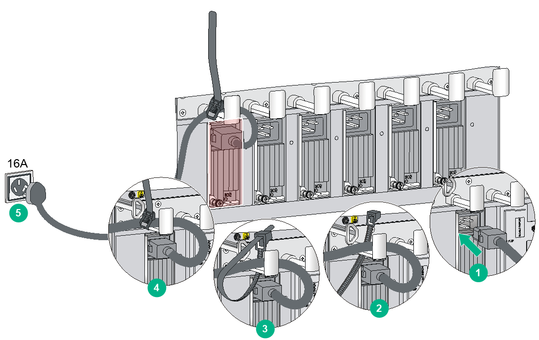
Figure 12 Securing the power cord (method two)
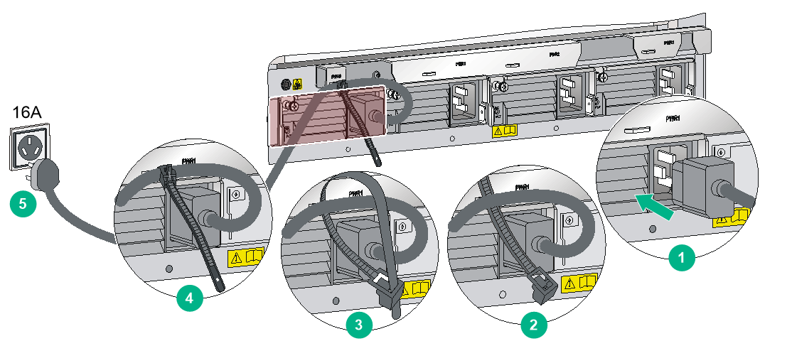
Figure 13 Securing the AC power cord (method three)
Connecting a DC power cord
|
|
WARNING! · Make sure each DC power cord has a separate circuit breaker. · Before you connect a DC power cord, make sure the DC power source circuit breakers are turned off. |
Connecting a DC power cord to an LSUM1DC2400 or PSR2400-12D power supply
1. Connect the power cord to the power receptacle of the power supply.
2. Fasten the screw to secure the power cord.
Figure 14 Connecting a power cord to an LSUM1DC2400 or PSR2400-12D power supply (vertical slot)
3. (Optional) Use a cable tie to secure the power cord to the cable management bracket.
The same method is used for securing AC and DC power cords. For information about securing a DC power cord, see "Connecting an AC power cord."
For the CR16010H-F, CR16010H-FA,CR16018-FA, or CR16018-F router, each hook on the cable management bracket has a cutout. You can also feed the cable tie through the cutout to secure the power cord.
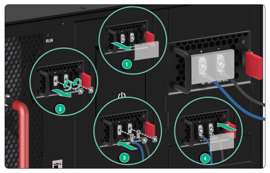
4. Connect the other end of the DC power cord to a DC power source, with the wire marked with –48V connected to the negative terminal (–48V) and the wire marked with RTN connected to the positive terminal (RTN).
Connecting a DC power cord to a PSR2400-D power supply
|
|
WARNING! A DC power cord includes a negative wire and a positive wire. When connecting the power cord to the power source, make sure the circuit breaker switches for the positive wire and the negative wire are both turned off. |
|
|
IMPORTANT: To meet the current requirements and match the terminals on the PSR2400-D power supplies, use the power cords or power cord lugs provided by H3C. |
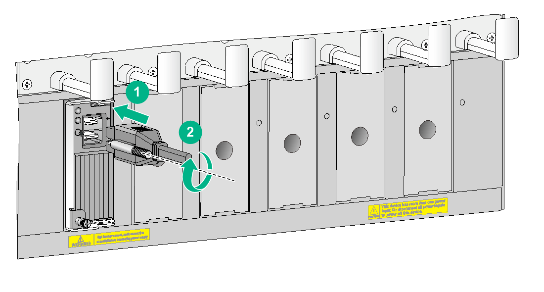
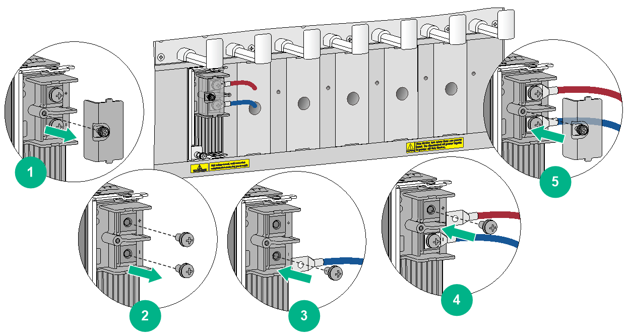
To connect a DC power cord to a PSR2400-D power supply:
1. Use a Phillips screwdriver to loosen the screw on the terminal protection cover and then remove the protection cover from the power supply.
2. Use a Phillips screwdriver to loosen the screws on the wiring terminals.
3. Connect the DC power cord to the power supply.
a. Connect the wire marked with – to the negative terminal (–) on the power supply and fasten the screw.
b. Connect the wire marked with + to the positive terminal (+) on the power supply and fasten the screw.
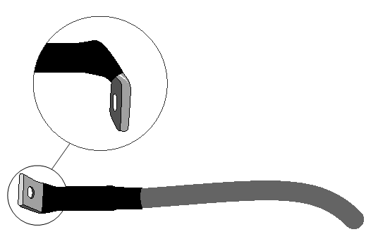
Use a heat-shrink tubing to cover the joint between the lug and the power wire. Make sure the heat-shrink tubing wraps the root of the lug.
Figure 15 Covering the joint with the heat-shrink tubing
4. Place the protection cover over the wiring terminals and fasten the screw.
Figure 16 Connecting a power cord to a PSR2400-D power supply (vertical slot)
5. Connect the end of the DC power cord to a DC power source, with the wire marked with – connected to the terminal marked with –48V(–) and the wire marked with + connected to the terminal marked with RTN (+).
Connecting a DC power cord to a PSR2000-12D-B power supply
1. Remove the protection cover from the power supply.
2. Use a Phillips screwdriver to loosen the screws on the wiring terminals.
3. Connect the DC power cord to the power supply.
a. Connect the wire marked with – to the negative terminal (–) on the power supply and fasten the screw.
b. Connect the wire marked with + to the positive terminal (+) on the power supply and fasten the screw.
c. Install the removed protection cover to the power supply
Figure 17 Connecting a DC power cord to a PSR2000-12D-B power supply (CR16005E-F)
4. Connect the end of the DC power cord to a DC power source, with the wire marked with – connected to the terminal marked with –48V(–) and the wire marked with + connected to the terminal marked with RTN (+).
(Optional) Installing transceiver modules
|
|
WARNING! Disconnected optical fibers or transceiver modules might emit invisible laser light. Do not stare into beams or view directly with optical instruments when the router is operating. |
|
|
CAUTION: To avoid transceiver module or port damage, read this guide carefully before installing a transceiver module. |
|
|
CAUTION: · Be careful not to touch the golden plating on a transceiver module during the installation process. · Before installing a transceiver module, remove the optical fibers, if any, from it. · Make sure the transceiver module is aligned correctly with the target port before pushing it into the port. · Do not remove the dust plugs from a transceiver module until you are ready to connect optical fibers to it. |
Installing an XFP/QSFP+/QSFP28/SFP28/SFP+/SFP transceiver module
The installation procedure is similar for XFP, QSFP+, QSFP28, SFP28, SFP+, and SFP transceiver modules. The following uses an SFP+ transceiver module for illustration.
To install an SFP+ transceiver module:
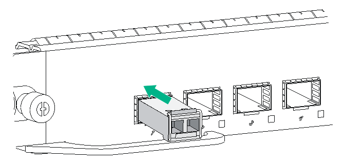
1. Wear an ESD wrist strap and make sure it makes good skin contact and is reliably grounded. For more information, see "Attaching an ESD wrist strap."
2. Remove the dust plug from the target fiber port.
3. Unpack the transceiver module.
4. As shown in Figure 18, close the bail latch upward to catch the knob on the top of the transceiver module. Then correctly orient the transceiver module and align it with the fiber port, and push it gently into the port until you feel it snap into place.
Transceiver modules and fiber ports have disorientation rejection designs. If you cannot insert a transceiver module easily into a port, the orientation might be wrong. Remove and reorient the transceiver module.
In case of limited space, you can gently push against the front face of the transceiver module instead of the two sides.
5. If you are not to install an optical fiber, insert a dust plug into the transceiver module bore.
6. Connect a fiber to the module. For the installation procedure, see "Connecting your router to the network through optical fibers."
Figure 18 Installing an SFP+ transceiver module
Installing a CFP transceiver module
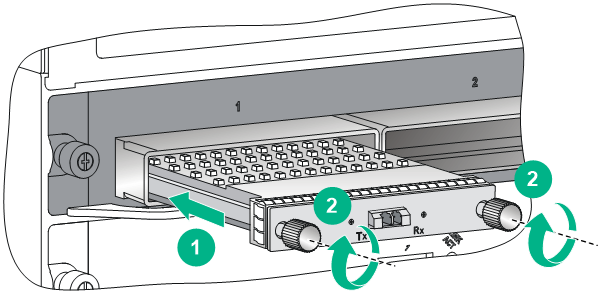
1. Wear an ESD wrist strap and make sure it makes good skin contact and is reliably grounded. For more information, see "Attaching an ESD wrist strap."
2. Remove the dust plug from the target fiber port.
3. Unpack the CFP module.
4. As shown in Figure 19, correctly orient the transceiver module and align it with the fiber port. Push it gently into the port until you feel it snaps into place.
Transceiver modules and fiber ports have disorientation rejection designs. If you cannot insert a transceiver module easily into a port, the orientation might be wrong. Remove and reorient the transceiver module.
In case of limited space, you can gently push against the front face of the transceiver module instead of the two sides.
5. Fasten the captive screws on the transceiver module to secure it in place.
If a screw cannot be fastened, adjust the CFP transceiver module and the screw and re-fasten the screw, or remove the CFP transceiver module and then reinstall it.
6. Connect a fiber to the module. For the installation procedure, see "Connecting your router to the network through optical fibers."
Figure 19 Installing a CFP transceiver module
Installing a CFP2 transceiver module
1. Wear an ESD wrist strap and make sure it makes good skin contact and is reliably grounded. For more information, see "Attaching an ESD wrist strap."
2. Unpack the CFP2 transceiver module.
3. Pivot the module handle up onto the top of the module and orient the module with the handle above the ports. Gently push the module into the port until the spring tabs on the two sides of the module click into place. See Figure 20.
Figure 20 Installing a CFP2 transceiver module
Connecting an E1 cable
1. Wear an ESD wrist strap and make sure it makes good skin contact and is reliably grounded. For more information, see "Attaching an ESD wrist strap."
2. Connect the HD96 connector of the E1 cable to the interface on the subcard and use a screwdriver to fasten the screws on the connector.
3. Connect the other end of the E1 cable to the peer device.
Figure 21 Installing an E1 cable
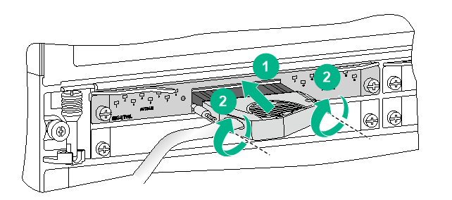
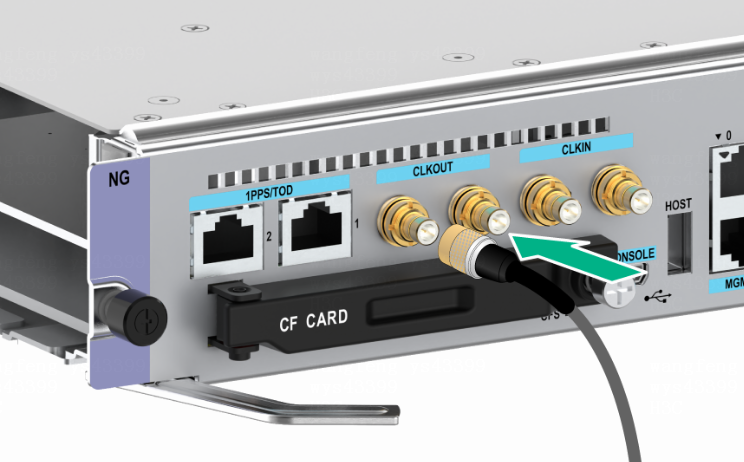
Installing an SMB coaxial clock cable
1. Wear an ESD wrist strap and make sure it makes good skin contact and is reliably grounded. For more information, see "Attaching an ESD wrist strap."
2. Remove the dust plug from the target clock port.
3. Insert the SMB connector of the SMB coaxial clock cable into the clock port.
4. Connect the other end of the SMB coaxial clock cable to the peer network device.
Figure 22 Installing an SMB coaxial clock cable